PRESSURE 5 CLICK
PID: MIKROE-3566
Weight: 18 g
Pressure 5 click is a barometric pressure measurement Click board™, which features the BMP388,
an accurate absolute barometric pressure sensor. Due to its very high sensing accuracy, it is
perfectly suited for precise altitude tracking applications. The BMP388 pressure sensor can use both
SPI and I2C communication protocols, allowing it to be interfaced with a broad range of MCUs. The
BMP388 features onboard processing capabilities such as the IIR filtering, which can be used to
filter out abrupt pressure changes. Thanks to its very low power consumption, Pressure 5 click to be
used in a wide range of battery-powered and portable applications.
Pressure 5 click is supported by a mikroSDK compliant library, which includes functions that simplify
software development. This Click board™ comes as a fully tested product, ready to be used on a
system equipped with the mikroBUS™ socket.
Besides the pressure readings, the Pressure 5 click also offers very accurate
temperature reading, which is required for the pressure readings compensation.
Oversampling up to 32 times combined with the filtering options allows very low noise
influence on measurement results. Depending on the application in which the Click
board™ is used, different power saving, oversampling, and filtering settings can be
�implemented, resulting in optimal performance in given conditions. All these features
make the Pressure 5 click an ideal solution for the development of portable weather
station applications, indoor navigation for flying toys and drones, and similar
applications that rely on reliable barometric pressure measurements.
HOW DOES IT WORK?
The sensor used on the Pressure 5 click is the BMP388, a digital pressure sensor,
from Bosch Sensortech. This sensor consists of a piezo-resistive pressure sensing
element and a mixed-signal ASIC which performs A/D conversions and provides the
conversion results through a digital interface. This advanced MEMS technology offers a
high measurement precision of 0.08hPa, as well as low TOC (thermal coefficient) of
only 0.75 Pa/K. The sensor is enclosed in a small metal lid housing and is highly
resilient: it can operate in a range of 300 hPa to 1250 hPa but can withstand up to
20,000 hPa before the membrane breaks down.
The BMP388 offers a set of pressure and temperature measurement options. It can be
programmed to skip either thermal or pressure measurement, allowing faster
measurement of the required property. The low TOC of only 0.75Pa/K allows reading of
the pressure with very small drift over temperature. Resolution of 0.08hPa allows
calculating of the altitude with the accuracy of about 66 cm, which is ideal for indoor
navigation applications (drones, flying toy models, and similar). The IIR filter is
especially useful for indoor usage, allowing filtering of some short-term disturbances,
such as slamming doors or windows.
FIFO buffer allows for an optimization of the host firmware, reducing the data traffic
through the communication interface. It has 512 bytes and it is backed up by an
interrupt engine, which can trigger an interrupt event when the buffer is full, or when the
watermark level is reached. Also, the behavior of the FIFO buffer can be programmed to
�either skip new data once it is full or to overwrite the oldest data. The interrupt is
available over the INT pin, and can be used to further optimize the host firmware (i.e. to
reduce the power consumption by utilizing the INT pin to wake up the host MCU).
Besides FIFO events, the INT pin also signals when there is a new data available at the
output register (Data Ready event).
This sensor consists of a mixed signal front-end (ASIC) and a piezo-sensitive pressure
sensing element. The ASIC contains a low-noise 24-bit A/D converter, along with the
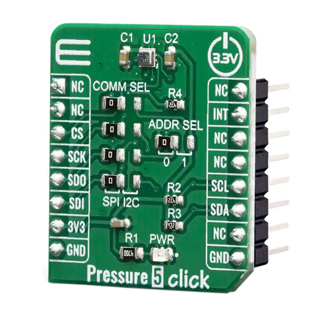
digital signal processing section. The measurement data is available either over the I2C
or the SPI interface. Pressure 5 click offers a choice between these two interfaces. The
selection can be done by positioning SMD jumpers labeled as COMM SEL to an
appropriate position. Note that all the jumpers must be placed to the same side, else the
Click board™ may become unresponsive. While the I2C interface is selected, the
BMP388 allows the choice of the least significant bit (LSB) of its I2C slave address. This
can be done by using the SMD jumper labeled as ADDR SEL.
The overall power consumption depends on several factors, such as the oversampling
value, measurement rate, power mode, standby duration, and so on. Bosh Sensortech
recommends a set of operational parameters for different applications, in the form of a
table, in the BMP388 datasheet. In general, this sensor allows several power modes,
regardless of the selected measurement parameters:
Sleep mode: keeps only the logic section of the sensor IC powered. It is possible to read the device
ID and compensation parameters. The power consumption is minimal in this mode.
Forced mode: when the Forced mode command is received, the device is awakened from the sleep
mode; a single measurement is performed, according to previously programmed conversion
parameters. After that, the device reverts to the Sleep mode, waiting to be triggered once more by
repeated selection of the Force mode. The conversion results can be read from the registers since
the Sleep mode keeps the logic section powered up.
Normal mode: in this mode, conversions are cyclically repeated, with programmable standby periods
after each measurement. The power consumption in this mode varies with the standby period
duration. Once selected, the cycle repeats, so there is no need to repeat the Normal mode
command.
When the measurement is completed, raw ADC values will be available in the output
registers. However, to obtain actual pressure and temperature readings, a
compensation algorithm needs to be applied. A set of compensation parameters is
available in the non-volatile memory of the BMP388 device. These compensation
parameters take into account slight differences between the produced samples and
each BMP388 device has its own set of parameters. The BMP388 datasheet offers
detailed instructions on how to apply these compensating algorithms properly. However,
MikroElektronika provides a library with functions which can be used for a simplified and
thus faster application development. The library also contains a demo example, which
demonstrates the use of these functions. The demo application can be used as a
reference for a custom design.
�SPECIFICATIONS
Type
Pressure
Applications
It can be used for weather stations, indoor flying toys navigation,
drones, variometers, and similar applications that rely on reliable
barometric pressure measurements.
On-board
modules
BMP388, a digital pressure sensor, from Bosh Sensortech.
Key Features
Very accurate pressure and temperature readings, on-chip IIR data
filtering, it can use either SPI or I2C communication protocol,
customizable power consumption in three different power modes,
etc.
Interface
I2C,SPI
Input Voltage
3.3V
Click board
size
S (28.6 x 25.4 mm)
PINOUT DIAGRAM
This table shows how the pinout on Pressure 5 click corresponds to the pinout on the
mikroBUS™ socket (the latter shown in the two middle columns).
Notes
SPI Chip Select
Pin
Pin
NC
1
AN
PWM
16
NC
NC
2
RST
INT
15
INT
CS
3
CS
RX
14
NC
Notes
Interrupt
�SPI Clock
SCK
4
SCK
TX
13
NC
SPI Data OUT
SDO
5
MISO
SCL
12
SCL
I2C Clock
SPI Data IN
SDI
6
MOSI
SDA
11
SDA
I2C Data
Power Supply
3.3V
7
3.3V
5V
10
NC
Ground
GND
8
GND
GND
9
GND
Ground
PRESSURE 5 CLICK ELECTRICAL SPECIFICATIONS
Description
Min
Typ
300
-
1250
hPa
-0.08
-
+0.08
hPa
Temperature range
-40
-
+85
˚C
Temperature measurement resolution
±0.3
-
±0.5
˚C
Pressure range
Pressure measurement resolution
Max
Unit
ONBOARD SETTINGS AND INDICATORS
Label
Name
Default
LD1
PWR
-
COMM
SEL
COMM SEL
Left
Description
Power LED Indicator
Communication protocol selection: left position
SPI, right position I2C
�ADDR
SEL
ADDR SEL
Left
I2C Address selection bit: left position 0, right
position 1
SOFTWARE SUPPORT
We provide a library for the Pressure 5 click on our LibStock page, as well as a demo
application (example), developed using MikroElektronika compilers. The demo can run
on all the main MikroElektronika development boards.
Library Description
The library initializes and defines the I2C or SPI bus driver and drivers that offer a
choice for writing data in register and reads data form register. The library includes
function for read Pressure data in mBar and Temperature data in C. The user also has
the function for update all calibration coefficients, function for software reset, read
Interrupt state and functions for get Pressure and Temperature raw data.
Key functions:
float pressure5_getTemperatureData() - Temperature data in C.
float pressure5_getPressureData() - Pressure data in mBar.
void pressure5_updateCoefficient() - Update calibration coefficients.
Examples description
The application is composed of the three sections :
System Initialization - Initializes I2C or SPI module, sets INT pin as INPUT and CS pin as OUTPUT.
Application Initialization - Initialization driver init, test comunication, software reset, update coefficient
and configuration module for start measurement.
Application Task - Reads Pressure data in [mBar] and Temperature data in [C]. Logs all data to the
USBUART every 1500ms.
void applicationTask()
{
float Temperature;
float Pressure;
char demoText[ 50 ] = {0};
Temperature = pressure5_getTemperatureData();
FloatToStr(Temperature, demoText);
mikrobus_logWrite(" Temperature: ", _LOG_TEXT);
mikrobus_logWrite(demoText, _LOG_TEXT);
mikrobus_logWrite(" C", _LOG_LINE);
�
Pressure = pressure5_getPressureData();
FloatToStr(Pressure, demoText);
mikrobus_logWrite(" Pressure: ", _LOG_TEXT);
mikrobus_logWrite(demoText, _LOG_TEXT);
mikrobus_logWrite(" mBar ", _LOG_LINE);
mikrobus_logWrite("‐‐‐‐‐‐‐‐‐‐‐‐‐‐‐‐‐‐‐‐‐‐‐‐‐‐", _LOG_LINE);
Delay_ms( 1500 );
}
The full application code, and ready to use projects can be found on our LibStock page.
Other mikroE Libraries used in the example:
SPI
UART
I2C
Conversions
Additional notes and informations
Depending on the development board you are using, you may need USB UART
click, USB UART 2 click or RS232 click to connect to your PC, for development systems
with no UART to USB interface available on the board. The terminal available in all
MikroElektronika compilers, or any other terminal application of your choice, can be
used to read the message.
MIKROSDK
This click board is supported with mikroSDK - MikroElektronika Software Development
Kit. To ensure proper operation of mikroSDK compliant click board demo applications,
mikroSDK should be downloaded from the LibStock and installed for the compiler you
are using.
For more information about mikroSDK, visit the official page.
�
https://www.mikroe.com/pressure‐5‐click/5‐15‐19
�


 工商网监
湘ICP备2023018690号
工商网监
湘ICP备2023018690号
