PPMT12V4
P-Channel MOSFET
Description
The enhancement mode MOS is extremely high density cell and low on-resistance.
D(3)
MOSFET Product Summary
VDS(V)
RDS(on)(Ω)
ID(A)
-12
0.045 @ VGS=-4.5V
-4.3
G(1)
S(2)
Absolute maximum rating@25℃
Rating
Symbol
Value
Units
Drain-Source Voltage
VDS
-12
V
Gate-Source Voltage
VGS
±8.0
V
Drain Current
Continuous
TA=25℃
ID
-4.3
A
Pulsed
TA=70℃
ID
-3.4
A
IDM
-34
A
TA=25℃
PD
1.3
W
TA=125℃
PD
0.8
W
0.01
W/℃
EAS
33
mJ
TJ,TSTG
-55 to +150
℃
Pulsed Drain Current
Total Power Dissipation
Linear Derating Factor
Single Pulse Avalanche Energy
Junction and Storage Temperature Range
Thermal resistance
Parameter
Maximum Junction-to-Ambient
Rev.06
Symbol
Typ.
Max.
Units
RθJA
75
100
℃/W
1
www.prisemi.com
�P-Channel MOSFET
PPMT12V4
Electrical characteristics per line@25℃( unless otherwise specified)
Parameter
Symbol
Conditions
Min.
Typ.
Max.
Units
Drain-Source Breakdown Voltage
BVDSS
ID =-250μA,VGS=0V
-12
-
-
V
Zero Gate Voltage Drain Current
IDSS
VDS =-12V,VGS=0V
-
-
-1.0
μA
Gate-to-Source Forward Leakage
IGSS
VGS=-8.0V
-
-
-100
nA
Gate Threshold Voltage
VGS(th)
VDS =VGS, ID =-250μA
-0.45
-0.7
-1.0
V
VGS=-4.5V, ID =-4.3A
-
-
0.045
Ω
VGS=-2.5V, ID =-2.5A
-
-
0.060
Ω
VGS=-1.8V, ID =-2.0A
-
-
0.100
Ω
VDS=-10V, ID =-4.3A
8.6
-
-
S
-
7.8
-
1.4
-
1.6
-
750
pF
-
230
pF
pF
Static Drain-Source On-Resistance
RDS(ON)
Forward Trans conductance
gFS
Total Gate Charge
Qg
Gate-to-Source Charge
Qgs
Gate-to-Drain(Miller) Charge
Qgd
Input Capacitance
CISS
ID =-4.3A, VDS =-10V,
VGS =-5.0V
VGS=0V, VDS =-10V,
nC
Output Capacitance
CDSS
Reverse Transfer Capacitance
CRSS
-
160
Turn-On Delay Time
td(on)
-
11
-
Rise Time
tr
-
32
-
Turn-Off Delay Time
td(off)
-
250
-
Fall Time
tf
-
210
-
Min.
Typ.
Max.
Units
-
-
-1.6
A
-
-
-1.2
V
-
22
33
ns
-
8.0
12
nC
f=1MHz
VDD=-6.0V, ID =-1.0A,
RD=6.0Ω, RG=89Ω
ns
Source-Drain Rating and Characteristics
Parameter
Symbol
Conditions
MOSFET symbol showing
Continuous Source Current
(Body Diode)
the integral
IS
reverse p-n
junction
diode
Rev.06
Diode Forward Voltage
VSD
Reverse Recovery Time
trr
Reverse Recovery Charge
Qrr
TJ=25℃,IS=-1.3A,VGS=0V
TJ=25℃,IF=-1.3A,di/dt=-100A/μs
2
www.prisemi.com
�P-Channel MOSFET
PPMT12V4
Typical Characteristics
100
VGS
TOP -7.0V
-5.0V
-4.5V
-3.0V
-2.5V
-1.8V
-1.5V
Bottom -1.0V
10
1
-1.0V
0.1
1
-1.0V
0.1
0.01
0.1
100
10
1
10
20μs pulse width
TJ=150℃
20μs pulse width
TJ=25℃
0.01
0.1
1
Fig 1. Typical output characteristics
Fig 2. Typical output characteristics
Static Drain-Source On-State Resistance:
RDS(ON)(mΩ)
100
Drain-to-Soutce current: ID (A)
TJ=25℃
TJ=150℃
1.0
VDS=-12V
20μs pulse width
0.1
1.0
3.5
3.0
2.5
2.0
1.5
Gate-to-Source Voltage :VGS (V)
4.0
CISS
800
COSS
CRSS
200
1.0
0.5
1
10
VGS=-4.5V
-20
100
20
60
Junction Temperature :TJ (℃)
140
100
Drain-to-Source Volatge :VDS (V)
Fig 5. Typical Capacitance vs. Drain-to-Source
ID=-4.3A
8
VDS=-10V
6
4
2
0
0
0
8
4
12
Total Gate Charge :QG (nC)
18
Fig 6. Typical Gate Charge vs. Gate-to-Source
voltage
Rev.06
1.5
10
VGS=0V,f=1MHz
CISS=Qgs+Qgd Shorted
CRSS=Qgd
COSS=Qds+Qgd
600
400
ID=-4.3A
Fig 4. Normalized On-Resistance vs, Temperature
Gare-to-Source voltage: VGS (V)
C, Capacitance (pF)
1000
2.0
0.0
-60
Fig 3. Typical transfer characteristics
1200
100
10
Drain-to-Source Voltage :VDS (V)
Drain-to-Source Voltage :VDS (V)
10
VGS
-7.0V
-5.0V
-4.5V
-3.0V
-2.5V
-1.8V
-1.5V
Bottom -1.0V
TOP
Drain-to-Source Current: ID(A)
Drain-to-Source Current: ID(A)
100
voltage
3
www.prisemi.com
�P-Channel MOSFET
PPMT12V4
1000
10
Drain Current: ID (A)
Reverse Drain Current :ISD (A)
100
Tj=150℃
TJ=25℃
1
Operation in this area limited by
RDS(on)
100
10us
10
100us
1ms
1
0.1
VGS=0V
0.1
0.01
1.8
1.4
0.6
1.0
Source-to-Drain voltage :VSD (V)
0.2
Fig 8. Maximum Safe Operating Area
80
Single Pulse Avalanche Energy: EAS (mJ)
5.0
4.0
3.0
2.0
1.0
0.0
25
125
100
75
Case Temperature:TC (℃)
50
1
0.1
Drain-to-Source voltage: VDS (V)
Fig 7. Typical Source-Drain Diode Forward Voltage
Drain Current: ID(A)
10ms
TC=25℃
TJ=150℃
Single Pulse
ID
-1.9A
-3.4A
Bottom -4.3A
TOP
60
40
20
0
25
150
Fig 9. Maximum Drain Current vs. Case Temperature
50
75
100
125
Junction Temperature : Starting TJ (℃)
150
Fig 10. Maximum Avalanche Energy vs. Drain
Current
Thermal Response (ZthJA)
1000
100
ID=0.50
0.20
10
1
0.10
0.05
0.02
0.01
0.1
0.00001
PDM
t1
Single Pulse
(Thermal Response)
0.0001
t2
Notes:
1.
Duty factor D=t1/t2
2.
Peak TJ=PDM*ZthJA+TA
0.001
0.01
0.1
1
10
Rectangular Pulse Duration (sec)
Fig 11. Maximum Effective Transient Thermal Impedance, Junction-to-Ambient
Rev.06
4
www.prisemi.com
�P-Channel MOSFET
PPMT12V4
0.20
Drain-to-Source On Resistance: RDS(on) (Ω)
Drain-to-Source voltage: RDS(on) (Ω)
0.10
0.08
0.06
ID=-4.3A
0.04
0.02
1.0
2.0
3.0
4.0
5.0
6.0
7.0
Gate-to-Source voltage: VGS (V)
Fig 12. Typical On-Resistance vs. Gate Voltage
VGS=-1.8V
VGS=-2.5V
0.15
0.10
VGS=-4.5V
0.05
0.0
0
10
30
20
Drain Current: ID (A)
40
Fig 13. Typical On-Resistance vs. Drain Current
Gate threshold Voltage: VGS(th) (Ω)
0.8
0.7
0.6
ID=-250μA
0.5
0.4
0.3
-75
-50
0
50
Temperature: TJ (℃)
100
150
Fig14. Typical Threshold Voltage vs.
Junction Temperature
Rev.06
5
www.prisemi.com
�P-Channel MOSFET
PPMT12V4
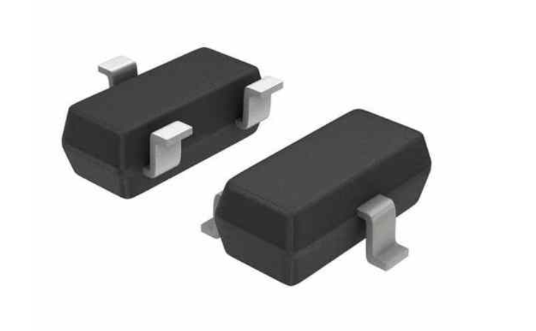
Product dimension(SOT-23)
A
(3)
C
θ
B
(1)
H
(2)
D
F
G
E
J
L
K
Millimeters
Inches
Dim
Rev.06
MIN
MAX
MIN
MAX
A
2.80
3.00
0.1102
0.1197
B
1.20
1.40
0.0472
0.0551
C
2.10
2.50
0.0830
0.0984
D
0.89
1.02
0.0350
0.0401
E
0.45
0.60
0.0177
0.0236
F
1.78
2.04
0.0701
0.0807
G
0.085
0.177
0.0034
0.0070
H
0.45
0.60
0.0180
0.0236
J
0.37
0.50
0.0150
0.0200
K
0.89
1.11
0.0350
0.0440
L
0.013
0.100
0.0005
0.0040
θ
0°
10°
0°
10°
6
www.prisemi.com
�P-Channel MOSFET
PPMT12V4
IMPORTANT NOTICE
and
are registered trademarks of Prisemi Electronics Co., Ltd (Prisemi) ,Prisemi
reserves the right to make changes without further notice to any products herein. Prisemi makes
no warranty, representation or guarantee regarding the suitability of its products for any particular
purpose, nor does Prisemi assume any liability arising out of the application or use of any
product or circuit, and specifically disclaims any and all liability, including without limitation
special, consequential or incidental damages. “Typical” parameters which may be provided in
Prisemi data sheets and/or specifications can and do vary in different applications and actual
performance may vary over time. All operating parameters, including “Typicals” must be
validated for each customer application by customer’s technical experts. Prisemi does not
convey any license under its patent rights nor the rights of others. The products listed in this
document are designed to be used with ordinary electronic equipment or devices, Should you
intend to use these products with equipment or devices which require an extremely high level of
reliability and the malfunction of with would directly endanger human life (such as medical
instruments, aerospace machinery, nuclear-reactor controllers, fuel controllers and other safety
devices), please be sure to consult with our sales representative in advance.
Website: http://www.prisemi.com
For additional information, please contact your local Sales Representative.
©Copyright 2009, Prisemi Electronics
is a registered trademark of Prisemi Electronics.
All rights are reserved.
Rev.06
7
www.prisemi.com
�
很抱歉,暂时无法提供与“PPMT12V4”相匹配的价格&库存,您可以联系我们找货
免费人工找货- 国内价格
- 1+0.28651
- 100+0.26741
- 300+0.24831
- 500+0.22920
- 2000+0.21965
- 5000+0.21392


 工商网监
湘ICP备2023018690号
工商网监
湘ICP备2023018690号
