T
TRUS
THE INAL
ORIG
XLR Connectors
�X L R
Content
C o n n e c t o r s
Page
Cable Connectors:
XX Series .................................................................. 4
XLR TOP® Series ......................................................... 4
RX Series .................................................................. 5
XX-HE Series ............................................................. 5
XX-14 Series ............................................................. 6
XX Crimp Series ........................................................ 6
crystalCON ® . ............................................................... 7
EMC-XLR Series ......................................................... 7
convertCON® . .............................................................. 8
X Series ..................................................................... 8
X-HD Series ............................................................... 9
XCC Series ................................................................ 9
FXS Series ................................................................. 10
FX-SPEC Series .......................................................... 10
8 + 2 pole XLR Type Data Power Connector ................ 11
Technical Data ........................................................... 12
Ordering Information ................................................. 14
Accessories ............................................................... 16
Receptacles:
A Series ....................................................................
AA Series ..................................................................
B Series ....................................................................
A / B Series - Switch ...................................................
XLR TOP ® Series ........................................................
D Series ....................................................................
DL Series ..................................................................
DLX Series ................................................................
DLX Crimp Series ......................................................
EMC Series ...............................................................
MPR-HD Series ..........................................................
P Series ....................................................................
Combo I Series .........................................................
Combo A Series ........................................................
Technical Data ..........................................................
Ordering Information ...............................................
Accessories . ..............................................................
18
18
19
19
20
20
21
21
22
22
23
23
24
25
26
28
31
General Information:
Definitions, Abbreviations & Useful Information .......... 33
Neutrik Part Number Guide ....................................... 34
Neutrik Product Line ................................................. 35
2
setting standards
XLR Connectors
�X L R
C o n n e c t o r s
Introduction
Neutrik XLR connectors are the most well-known series of
products manufactured by Neutrik, and have provided the
professional audio industry a simple, yet striking, concept
in connector features. We introduced our first XLR product
40 years ago. Today it is the accepted standard worldwide.
XLR connectors are part of almost every aspect of professional audio; as a microphone connector, in lighting systems, and found in almost any piece of sound equipment
in the entertainment industry. The outstanding success of
our XLR products is Neutrik’s blend of innovation with the
highest quality performance.
www.neutrik.com
3
�
X L R
Ergonomic latch
design
C a b l e
White painted
housing
C o n n e c t o r s
Rubber sealing
protection
XX Series
NC3FXX
IP65 in mated
condition
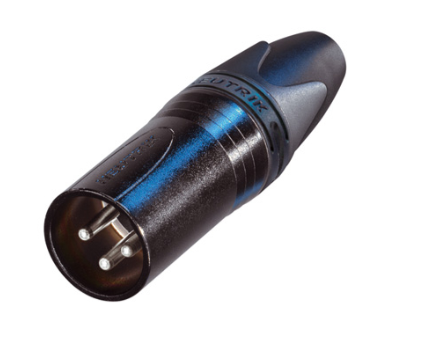
XLR TOP Series
NC6MXX-B
• The next generation of the worldwide accepted standard
• Unique cage type female contact – increases conductivity
• Female contact with “solder stop” for ease of soldering
• Male connector without locking “window” – more robust
housing, increases durability
• Improved chuck type strain relief - increases retention force
and makes assembly easier and faster
• New ground contact – excellent contact integrity between
chassis and cable connector
• Customized branding using translucent ring
• Sleek and ergonomic design – valuable and handy
• Internal thread on shell is well protected against any
damage
NC3FX-TOP
NC3MX-TOP
• Heavy-duty sealed XLR connector range
• 3 and 5 pin cable connector
• IP65 rating and certified outdoor protection to UL 50E
(in combination with a TOP range counterpart)
• Uses high impact UV resistant materials per UL
• Gold plated contacts
• Maintains sealing when in use and when disconnected
NC*FXX
NC*FX-TOP
NC*MXX
NC*MX-TOP
*: 3 - 7 contacts
*: 3 & 5 contacts
20190304 - N.Battlogg
4
setting standards
�
X L R
C a b l e
Right angle male
connector
C o n n e c t o r s
High temperature
resistant insulator
RX Series
NC3FRX-BAG
Velour chromium
housing
XX-HE Series
Outlet position
NC3FXX-HE
NC3MXX-HE
• Right angle version of the XX Series – only 20 mm wide
• Exclusive "High End" version of standard XX Series
• Extra slim right-angle connector
• Premium velour chromium plating provides soft satin finish
• Neutrik chuck type strain relief
• Extra high temperature resistant insulator material rated
• 5 selectable cable outlet positions on female &
to 280 °C (536 °F)
7 position on male connectors
• Machined female contacts standard
• Insert is dark grey to distinguish it from standard XX-Series
insulators
• Flammability UL 94V-0
NC*FRX
NC*MRX
NC3FXX-HE
NC3MXX-HE
*: 3 - 7 contacts
www.neutrik.com
5
�
X L R
C a b l e
Large cable outlet
C o n n e c t o r s
Ergonomic latch
design
XX-14 Series
NC3FXX-14
NC3MXX-14-B
XX Crimp Series
NC3FXX-HA-BAG
NC3MXX-HA
• Special version of the XX Series XLR cable connector for
• 3 pin XX Series with crimp contacts
large cable diameters
• Accommodates wire size AWG 24 - 22 or 0.22 – 0.34 mm2
• Incorporates all the features of the XX product series
• Absolute leadfree and solderless connection:
• Rear boot features large opening for use with cable O.D.
- RoHs compliant
8.0 – 10.0 mm
- health and eco-friendly
• Bulk packed; must be ordered in multiples of 100
• Fast and easy assembly
• Gas-tight connection offers constant contact resistance
• Ideal solution for field and on-site termination
6
NC3FXX-14
NC3FXX-HA
NC3MXX-14
NC3MXX-HA
setting standards
�
X L R
C a b l e
CRYSTALLIZEDTM – Swarovski
Elements
Circumferential
ground shield
contact
crystalCON
NC3FXX-B-CRYSTAL
EMC-XLR Series
NC3MXX-B-CRYSTAL
• 3 pole XLR XX-Series embellished with CRYSTALLIZEDTM –
Swarovski Elements
• Exclusively with gold plated contacts, and black chrome
housing
• Fancy, noble, valuable, attractive package – an eye-catcher
• With all benefits of the XLR XX-Series
C o n n e c t o r s
NC3FXX-EMC
NC3MXX-EMC
• 3 pole male / female XLR cable connector with integrated
capacitive shield to shell connection to avoid RF-interference
and LF-noise
• 360° shield contact on female connector ensures best
possible shielding and chassis contact
• Avoid ground loops as there is no LF-shield connection to
ground
• Patented
1
Contact #1
Connector shell
Annular capacitor
Inductance
NC3FXX-B-CRYSTAL
Cable shield
1 Design guarantees a continuous RF-shield connection but avoids
ground loops (no LF-shield connection)
2 Circular capacitor enables low-inductive shield connection to
connector housing
3 Cable shield - PIN 1 connection includes EMI suppression bead
NC3MXX-B-CRYSTAL
(blocks high frequencies)
3
2
1
cable shield
3
2
signal contacts
ground contacts
ferrite bead
connector shell
www.neutrik.com
7
�
X L R
C a b l e
convertCON position male – female
C o n n e c t o r s
Female locking
Male metal locking
window
convertCON
NC3FM-C-B
X Series
NC3FM-C
NC3FX
NC3MX + BSX-5
• World's first unisex XLR cable connector
• The worldwide XLR connector standard
• 3 pole male and female cable connector in one housing
• Available in 3 – 7 pin configuration including 6 pin
• Easy selectable gender – converted by sliding housing back
Switchcraft® configuration
and forth
• Assembly is quick and easy – no screws or special tools
• Substitutes adapters, ideal as an emergency kit
required
• Exclusively with gold plated contacts
• Unique Neutrik chuck type strain relief
• With all benefits of the XLR XX-Series
• Female shell features rubber ring for secure mating to male
XLR or microphone
Convert
• Sleek profile and compact design
male – female
• Rugged diecast shell
and vice versa
• UL recognized components
NC3FM-C: Position female
NC*FX
NC3FM-C: Position male
NC*MX
*: 3 - 7 contacts
8
setting standards
�
X L R
Rubber sealing
protection
C a b l e
Metal bushing
C o n n e c t o r s
Coding ring
XCC Series
X-HD Series
NC5FX-HD
NC4MX-HD
NC3FXCC
• "Heavy duty" cable connectors for outdoor use
• Coaxial ground spring and hex crimp ferrule at cable
• All metal design, male stainless steel
entrance allow continuous (360°) ground connection to
• NC*FX-HD mates with NC*MPR-HD chassis connector and
shell which is essential when transmitting low level
NC*MX-HD
audio signals
• Dust and water resistant according IP 65 in mated condition
• Includes Zebra coding ring to indicate digital AES signals
• Available in 3 – 5 pin configuration
• Ground contact uses 6.5 mm (.255") size "E" hex crimp
• Metal bushing including O-ring
(IEC 60803). Use part # HX-R-BNC with DIE-R-BNC-PT
NC*FX-HD
NC3FXCC
NC*MX-HD
NC3MXCC
*: 3 - 5 contacts
www.neutrik.com
9
�
X L R
C a b l e
Switch activating ring
C o n n e c t o r s
Locking ring
FXS Series
NC3FXS
FX-SPEC Series
NC3FXS-B
NC3FX-SPEC
• Available exclusively in a 3 pin female configuration
• Available in a 3 pin female standard configuration with
• Features a noiseless ON / OFF switch which shorts pins
gold plated contacts
2 and 3 together muting the signal voltage between
• Features a locking ring which is secured with a M 2.5
conductors
screw and 1.27 mm allen wrench
• For use with a microphone that does not have its own
• Offers the highest security protection for your microphones
On / Off switch
• Protects against accidental disconnects and theft
• Rugged zinc diecast shell, long lasting and durable
• Black chrome housing and locking ring
• Chuck type strain relief system for secure clamping of
• Eliminates movements and noises
cables
• Boot with rubber gland gives high protection against
bending stresses
NC3FXS
10
NC3FX-SPEC
setting standards
�
D a t a
NEW 8 + 2 pole
cable connector
Ergonomic latch
design
P o w e r
New 8 + 2 pole
D-size receptacle
C o n n e c t o r
Solder termination
X L R Ty p e D a t a P o w e r C o n n e c t o r s – 8 + 2 p o l e
NC10FXX-14-B
• Suitable for data offering CAT 5e performance and power up
NC10FRX-14-B
NC10MD-LX-B
8 + 2 pole Contact Arrangement:
to 16 A and 50 V - exceeds PoE+ capabilities
• Superior ruggedness compared to RJ45 type connectors
• All metal housing offers best overall RF protection and
electromagnetic shielding
• D-size housing provides installation compatibility with industry
standard D mounting dimensions
• Receptacle with duplex ground contact for excellent signal
integrity
NC10FXX-14-B
NC10FD-LX-B
NC10MXX-14-B
NC10MD-LX-B
www.neutrik.com
11
�
T e c h n i c a l
Specification
D a t a
XX &
XLR TOP
RX
XX-HE XX Crimp
XX-14 &
Series Series Series Series
crystalCON
EMC
Series
convertCON
Series
Electrical
Number of contacts
3 - 7 1)
3 - 5
3 - 7
3
3
3
3
Contact resistance ≤ 3 mΩ
Insulation resistance - initial: > 10 GΩ
- after damp heat test: > 1 GΩ
Dielectric strength 1.5 kV dc
Cable shield-shell connection choosable
-
capacitive
determined
- - - - -
Shielding effectiveness > 55 dB @ 1.3 GHz - - - - - Lossy ferrite bead on PIN 1
- - - - - Rated current per contact @ 35°C
3 pole: 16 A
1 A
5 A
4 pole: 10 A
- - -
-
5, 6 pole: 7.5 A
- -
-
7 pole: 5 A
- - -
-
Capacitance between contacts
3 pole: ≤ 4 pF
4, 5, 6 pole: ≤ 7 pF
- -
-
7 pole: ≤ 9 pF
- - -
-
Rated Voltage < 50 V ac
Mechanical
Lifetime
Insertion / withdrawal force
Cable O.D. range
Max. wire size
3 pole:
4 pole:
5, 6, 7 pole:
Crimp XX:
> 1`000 cycles
≤ 20 N
3.5 - 8.0 mm
2.5 mm2 / AWG 14
1.5 mm2 / AWG 16
1.0 mm2 / AWG 18
0.22 - 0.34 mm2 / AWG 24 - 22
≤ 50 N
2) 5.0 - 8.0 mm
AWG 16
-
- - -
AWG 16
- -
-
-
-
-
AWG 20
-
-
-
-
Material
Shell Zinc diecast (ZnAI4Cu1)
(F)
Stainless steel
-
(M)
- - - - velour Cr
Shell plating gal Ni or black Cr
Insert Polyamide PA 6.6
PPS 40% GR
Contacts
- female 3 pole: Bronze (CuSn8)
Brass
- female 4 – 7 pole & male: Brass (CuZn39Pb3)
-
Contact surface
Silver gal 2 µm Ag
- -
-
or Gold gal 0.2 µm Au hard alloy over 2 µm Ni
-
Latch lock
St3K32 (latch) / Ck 67 (spring)
-
- -
- -
Zinc diecast (ZnAI4Cu1) / CK67 (Spring) -
Strain-relief clamp POM
Bushing PA / PU
UV-resistant rubber
Circumferential ground spring
Bronze (CuSn6), Ni plated
- - - - - Crimp ferrule
Brass (CuZn39Pb3), Ni plated - - - - - - Coding ring
Polyamide PA 6 15% GR
- - - - - - Sealing jacket
EPDM
- - - - - - Securing ring
Brass (CuZn39Pb3)
- - - - - - -
Environmental
12
Operating temperature
Flammability
Protection class
Solderability complies with
Manufacturing Standard
-30 °C to +80 °C
UL 94 V-0 () / UL 94 HB (¡)
IP 40
IEC 68-2-20
IEC 61076-2-103
1)
2)
3)
: XX-14, CRYSTAL: 3 pole
: XX-14: Cable O.D. 8.0 – 10.0 mm
setting standards
¡
IP65 3)
: UL50E (mated)
�
T e c h n i c a l
D a t a
Specification
X XCC X-HD FXS
Series Series Series Series
FX-SPEC
Data
Series Power XLR
Electrical
3 - 7
3
3 - 5
3
3
8+2
Number of contacts
Contact resistance ≤ 3 mΩ
Insulation resistance
- initial: > 10 GΩ
- after damp heat test: > 1 GΩ
0.1 GΩ
Dielectric strength 1.5 kV dc
1 kV dc
Cable shield-shell connection choosable
-
-
determined
-
crimp
-
-
- Shielding effectiveness > 55 dB @ 1.3 GHz
-
- - - Lossy ferrite bead on PIN 1
-
-
-
-
-
Rated current per contact
@ 35°C
16 A (power pins)
3 pole: 16 A
4 pole: 10 A
- - -
5, 6 pole: 7.5 A
- - -
7 pole: 5 A
- - - -
3 A (data pins)
Capacitance between contacts
3 pole: ≤ 4 pF
4, 5, 6 pole: ≤ 7 pF
- - -
7 pole: ≤ 9 pF
- - - - Rated Voltage < 50 V ac
Transmission Performance
CAT 5e - - - - -
Mechanical
Lifetime > 1`000 cycles
Insertion / withdrawal force ≤ 20 N
5.4 - 6.2 mm
3.5 - 7.0 mm
Cable O.D. range 3.5 – 8.0 mm
8.0 - 10.0 mm
Max. wire size
3 pole: 2.5 mm2 / AWG 14
(2 power)
4 pole: 1.5 mm2 / AWG 16
- -
5, 6, 7 pole: 1.0 mm2 / AWG 18
- - -
(8 data)
Crimp tool: 6.5 mm Hex die (size "E" acc. to IEC 60803) -
- - - Crimp XX: 0.22 - 0.34 mm2 / AWG 24 - 22 - - - - - -
Material
Shell
Zinc diecast (ZnAI4Cu1)
Stainless steel
-
Shell plating
gal Ni or black Cr
-
-
female
male - - female
black Cr
Polyamide PA 6.6
Bronze (CuSn8)
-
-
Brass (CuZn39Pb3)
gal 2 µm Ag
- - -
gal 0.2 µm Au hard alloy over 2 µm Ni -
-
St3K32 (latch) / Ck 67 (spring)
Zinc diecast (ZnAI4Cu1) - - - - -
Strain-relief clamp POM
Bushing PA / PU
SS/PU
PU
Circumferential ground spring Bronze (CuSn6), Ni plated
-
- - - Crimp ferrule Brass (CuZn39Pb3), Ni plated
-
- - - Coding ring Polyamide PA 6 15% GR
-
- - - Sealing jacket EPDM
-
-
- - Securing ring
Brass (CuZn39Pb3) - - - -
Insert
Contacts
- female 3 pole:
- female 4 – 7 pole & male:
Contact surface
Silver
or Gold
Latch lock
Environmental
Operating temperature
Flammability
Protection class
Solderability complies with
Manufacturing Standard
-30 °C to +80 °C
UL 94 V-0
IP 40
IEC 68-2-20
IEC 61076-2-103
IP 65
www.neutrik.com
13
�
O r d e r i n g
I n f o r m a t i o n
Ordering Information for Cable Connectors
Female
Male
Shell
Contact - plating
3 pole
4 pole
5 pole
6 pole
7 pole
XX Series
NC*FXX
NC*MXX Nickel
NC*FXX-B
NC*MXX-B
Black Cr
NC*FXX-BAG
NC*MXX-BAG
Black Cr
NC3FXX-WT
NC3MXX-WT
White painted
NC3FXX-**-D 1 NC3MXX-**-D 1
Nickel / Black Cr
NC6FSXX 2 NC6MSXX 2
Nickel
NC6FSXX-B 2 NC6MSXX-B 2
Black Cr
NC6FSXX-BAG 2 NC6MSXX-BAG 2
Black Cr
Silver
Gold
Silver
Silver
Silver / Gold
Silver
Gold
Silver
-
-
-
-
-
-
-
-
-
-
-
-
Gold
-
- -
NC*MRX Nickel Silver
NC*MRX-B
Black Cr
Gold
NC*MRX-BAG
Black Cr
Silver
NC3MXX-HE
-
-
-
-
Silver
Gold
Silver
-
-
-
-
-
-
-
-
-
-
NC3MXX-HA Nickel
NC3MXX-HA-BAG Black Cr
Silver
Silver
- - - -
NC3MXX-B-CRYSTAL Black Cr
Gold
- - - -
Gold
Gold
Gold
Gold
- - - -
XLR TOP Series
NC*FX-TOP
NC*MX-TOP
Nickel / Black Cr
RX Series
NC*FRX
NC*FRX-B
NC*FRX-BAG
XX-HE Series
NC3FXX-HE
Velour Chromium Gold
XX-14 Series
NC3FXX-14-D
NC3FXX-14-B-D
NC3FXX-14-BAG-D
NC3MXX-14-D Nickel
NC3MXX-14-B-D
Black Cr
NC3MXX-14-BAG-D Black Cr
XX Crimp Series
NC3FXX-HA
NC3FXX-HA-BAG
- - - -
crystalCON
NC3FXX-B-CRYSTAL
XX-EMC Series
NC3FXX-EMC
NC3FXX-EMC-B
NC3MXX-EMC Nickel
-
Black Cr
-
-
-
-
-
-
-
convertCON Series
NC3FM-C
NC3FM-C-B
14
setting standards
Nickel
Black Cr
- - - -
�
O r d e r i n g
I n f o r m a t i o n
Ordering Information for Cable Connectors
Female
Male
Shell
Contact - plating
3 pole
4 pole
5 pole
6 pole
7 pole
X Series
NC*FX
NC*MX Nickel Silver
NC*FX-B
NC*MX-B
Black Cr
Gold
NC*FX-BAG
NC*MX-BAG
Black Cr
Silver
NC3FX-**-D 1 NC3MX-**-D 1
Nickel / Black Cr Silver / Gold
NC6FSX 2 NC6MSX 2
Nickel
Silver
NC6FSX-B 2 NC6MSX-B 2
Black Cr
Gold
NC6FSX-BAG 2 NC6MSX-BAG 2
Black Cr
Silver
-
-
-
-
-
-
-
-
-
-
- -
X-HD Series
NC*FX-HD
NC3FX-HD-B
NC*MX-HD Nickel
NC3MX-HD-B
Metal Black
Gold
Gold
NC3MXCC Nickel
Gold
- -
- -
-
-
Nickel
Black Cr
Gold
Gold
-
-
-
-
-
-
-
Black Cr
Gold
-
-
-
-
- - - -
XCC Series
NC3FXCC
FXS Series
NC3FXS
NC3FXS-B
FX-SPEC. Series
NC3FX-SPEC.
-
Ordering Information for 8 + 2 pole Data Power Connectors
Female
Male
Shell
Cable Connector
NC10FXX-14-B
NC10FRX-14-B
NC10MXX-14-B
NC10MRX-14-B
Black Cr
Black Cr
Gold
Gold
Receptacle
NC10FD-LX-B
NC10MD-LX-B
Black Cr
Gold
* :
Contact - plating
8 + 2 pole
Number of Contacts
**: Nickel or Black
–D1: Bulk packed, to be ordered in multiples of 100 pcs.
2
: Switchcraft Equivalent
www.neutrik.com
15
�
A c c e s s o r i e s
Colour Coded Accessories
Part No.
Description
BSX-*
Colored bushing for X Series
BXX-*
Colored bushing for XX Series
XCR-*
Colored coding ring for X Series
Black Brown Red Orange Yellow Green Blue Violet Grey White
0 1 2 3 4 5 6 7 8 9
XXR-*
Colored coding ring for XX Series
XXR-* NEO
Neon colored coding rings for XX Series
NEW
–
–
–
–
Accessories
BXX-CR
Bushing with translucent coding ring
BXX-14
Large bushing set (cable O.D. 8.5 mm)
XXCR
Translucent coding ring for XX Series
Label Dimensions: 57.9 mm x 6.35 mm –
2.25" W x 0.25" H)
BXX-CR
XXCR
A s s e m b l y To o l s
HTXP
Hand tool to tighten the XX and
PX-bushing
HTXX-14
Hand tool to tighten the XX-14 and
8 + 2 pole bushing
BTXX
Speed boot assembly tool to press the
XX boot onto shell
HX-R-BNC
Crimp tool for XCC Series
DIE-R-BNC-PT Crimp die for XCC Series (6.5 mm HEX)
DIE-R-HA-1
HTXP
BTXX-14
Crimp die for XX-HA Series
HX-R-BNC
DIE-R-BNC-PT
16
setting standards
Example
–
�
X L R
C a b l e
C o n n e c t o r s
www.neutrik.com
17
�
X L R
Smallest receptacle
C h a s s i s
Lateral right PCB
mount
C o n n e c t o r s
Locking release tab
A Series
Ground contact
Ergonomic
asymmetric locking
release tab
AA Series
NC3FAH
NC3MAV
NC3FAAV2
NC3MAAH-1
• Smallest XLR receptacles, highest packing density
• Front panel cutout and PCB layout 100% compatible to the
• Plastic housing
A Series
• Various grounding options
• Most cost-effective series
• "Tulip" type female contact design with high contact pressure
• "Tulip" type female contact design with high contact pressure
• Selective gold plated contact and PCB termination area for
• Selective gold plated contact and PCB termination area for
best conductivity and solderability
best conductivity and solderability
• Plastic housing flammability UL 94V-0 for 3 pole version only
• Plastic housing flammability UL 94 HB
NC5FAV
NC5FAH
NC3MAV-0
NC5MAH
NC3FAAH
NC3FAAV-0
Grounding Options (A / AA / B Series):
Female:
1:
Pin 1 & Panel & Shell connected, no separate ground contact
2:
Separate ground contact connected to shell & panel, separate Pin 1
w/o number: No ground / Shell contact (except 4 / 5 pole)
Male:
0:
Separate ground contact, connected to shell, separate Pin 1
1:
Pin 1 & Panel & Shell connected, no separate ground contact
w/o number: Separate ground contact connected to shell & panel,
separate Pin 1
18
setting standards
�
X L R
Front panel
grounding
C h a s s i s
Ergonomic
asymmetric locking
release tab
Incorporated switch
B Series
NC3FBV1
C o n n e c t o r s
A/B Series - Switch
NC4MBV
NC3MBV-SW
NC3FBV2-SW
• The B Series XLR receptable offers the same features as our
• A and B Series connector with additional switch
A Series product line with the added feature of a metal ring
• Normally open, normally closed (NO – NC) contact
• Metal ring on shell (nickel or black) offers complete EMC
• Switch activated by mating XLR cable connector
and RF protection
• Female versions available latchless
• Rear mount only
• "Tulip" type female contact
Inserting (Schematic):
• Plastic housing flammability UL 94V-0 for 3 pole version only
NC3FBV1
NC3FBV1
NC3FBV1
NC5FAV-SW
NC3MBV
NC5MBV-SW
NC3MBV
NC3MBV
www.neutrik.com
19
�
X L R
C h a s s i s
Locking release tab
C o n n e c t o r s
Removable insert
XLR TOP Series
NC3FDX-TOP
D Series
NC3MDX-TOP
NC3FDM3-H-B
NC3MD-V
• Heavy-duty sealed XLR connector range
• "D" shape metal shell
• 3 and 5 pin chassis connector
• Optimal RF protection using 3 shield contacts
• Outdoor protection acc. IP65 and UL 50E
• Horizontal and vertical PCB mount with separate
• Uses high impact UV resistant materials per UL
ground contact
• Gold plated contacts
• Mounting holes with M3 threads available
• Maintain sealing when in use and when disconnected
• 2 piece connector, insert is removable from shell
• Optional waterproof and UV resistant protection cap
• Front locked / unlocked insert
NC*FDX-TOP
NC3FD-V / NC3FD-H
NC*MDX-TOP
NC3MD-V / NC3MD-H
20190304 - N.Battlogg
*: 3 - 5 contacts
20
setting standards
�
X L R
Locking release tab
C h a s s i s
Horizontal PCB
mount
C o n n e c t o r s
Ground shielding
DL Series
NC3FD-L-1
White painted
housing
DLX Series
NC3FD-LX-HE
NC7MD-L-B-1
NC5MD-LX
• Unified "D" shape metal shell
• Next generation of the popular DL Series with greater
• Solder cups on 3 – 7 pole version
functionality
• Additional PCB mount on 4 and 5 pole
• All metal housing offers best overall RF protection and
• Front and rear mountable
electromagnetic shielding
• Duplex ground contact for excellent contact integrity
between chassis and cable connector
• Unique cage type female contact on 3 pole version increases
conductivity and reduces wear on the mated male contact
• Female contact incorporates a solder barrier to prevent
NC3FD-L-1
NC*FDM3-H
solder running into the contact mating area
• Larger solder contacts for easier termination
• Optional connection to easily join pin1 to chassis ground
• D-style housing provides installation compatibility with
industry standard D mounting dimensions
NC3MD-L-1
NC*MDM3-H
NC3FD-LX
NC*MD-LX
*: 3 - 5 contacts
*: 3 - 7 contacts
www.neutrik.com
21
�
X L R
C h a s s i s
Crimp type contact
C o n n e c t o r s
Circumferential
ground spring
DLX Crimp Series
NC3FD-LX-HA
EMC Series
NC3MD-LX-BAG-HA
NC3FDX-EMC-SPEC
• 3 pole DLX Series with crimp contacts
• 3 pole female XLR chassis connector with integrated
• Accommodates wire size AWG 24 – 22 or 0.22 – 0.34 mm2
• Utilizes standard B-type crimp tool (acc. IEC 60352-2)
and LF-noise
• Absolute leadfree and solderless connection:
• 360° shield contact ensures best possible shielding and
- RoHs compliance
chassis contact
- Health and eco-friendly
• D flange chassis for panel mount applications
• Fast and easy assembly
• Includes the locking nut of the NC3FX-SPEC for secure
• Gas-tight connection offers a constant contact resistance
fastening of a gooseneck for instance
• Ideal solution for field and on-site termination
• Special flange for large openings available
capacitive shield to shell connection to avoid RF-interference
• Patent pending
Detailed information of RF-shielding see page 7 – EMC
cable connector.
NC3FD-LX-HA
22
NC3MD-LX-HA
setting standards
NC3FDX-EMC-SPEC
�
X L R
C h a s s i s
Sealing gasket
C o n n e c t o r s
Through hole fastening
MPR-HD Series
NC3MPR-HD
P Series
NC5MPR-HD
NC3FP-1
NC6MP-B
• IP 65 – in combination with NC*FX-HD cable connectors
• Male and female available in 3 – 6 pin configurations;
• Perfect for outdoor applications
7 pin version available in female only
• Sealing gasket for water tight panel mount
• Smallest available hard wiring receptacles with large solder cups
• Gold plated contacts
• Male and female use different mounting hole dimensions
and do not fit in the same mounting hole
• Front mountable only
• One piece version – insert is NOT removable from shell
• Short female receptacle
NC5MPR-HD
• Compatible with Switchcraft® DxM, DxF; Cannon XLRx31, XLRx32
• 6 pole female version available with Switchcraft contact
arrangement
NC5FX-HD
NC3FP-1
NC3MPR-HD
NC3MP
*: 3 - 5 contacts
www.neutrik.com
23
�
X L R
Front end design
C h a s s i s
C o n n e c t o r s
Solder termination
Combo I Series
NCJ9FI-V
NCJ10FI-S
• Combined XLR receptacle and 1/4” phone jack
• Very low conductor capacitance, therefore suitable for
• Attractive “front end” design
digital audio
• Saves rack space by combining 2 connectors in one housing
• Fastening: Self-tapping Plastite® screws with thread
• Horizontal or vertical PCB mount or hard wire soldering
2.9 x 1.06 and tri-rondular configuration (A screw)
• Fully normalled
• Stereo or mono version
XLR receptacle or
1/4” phone jack
NCJ10FI-H
Wiring: Example of NCJ9FI-H
24
setting standards
S
SN
R
RN
T
TN
1/4"
1
2
3
G
XLR
�
X L R
Horizontal PCB
mount
C h a s s i s
Vertical PCB mount
C o n n e c t o r s
NEW: Ergonomic asymmetric
locking release tab
Combo A Series
NCJ6FA-V-0
NCJ6FA-H
NCJ6FA-V-0
• Combined 3 pole XLR receptacle and 1/4“ phone jack for bal-
• 3 pole female XLR combined with stereo TRS jack
anced mic and line or instrument inputs in one XLR housing
• Very low conductor capacitance – ideal for digital audio
• Dramatic space saving – 15 % over the predecessor Combo
• Front panel cut-out compatible with Neutrik XLR A Series
• Two connectors in one housing – substantial cost, material
and labour saving
• Horizontal and vertical PCB mount available
NCJ6FA-V
NCJ6FA-H
www.neutrik.com
25
�
T e c h n i c a l
Specification
D a t a
A
AA
B
XLR TOP
D
DL / DLX DLX
Series Series Series Series Series Series Crimp
Electrical
Number of contacts
3 - 5
3
3 - 5
3 - 5
3
3 - 7
3
Contact resistance
XLR: ≤ 6 mΩ
-
- - - - -
1/4"& switching contacts**: ≤ 20 mΩ
Insulation resistance - initial: > 10 GΩ
- after damp heat test: > 1 GΩ
Dielectric strength 1.5 kV dc
Rated voltage < 50 V ac
Rated current per contact
16 A
16 A
1A
3 pole: 6 A
- - -
10 A
4 pole: 6 A
-
7.5 A - 7.5 A
5, 6 pole: 3 A
- - - - -
7 pole: 5 A
- - - - - - Combo XLR + Jack contact 7.5 A
Capacitance between contacts
-
3 pole: ≤ 4 pF
-
-
4, 5, 6 pole: ≤ 7 pF
7 pole: ≤ 9 pF - - - - -
Mechanical
Lifetime > 1`000 mating cycles
Insertion / withdrawal force ≤ 20 N
Retention method
- standard: latch lock
- "0" Version: ≥ 20 N separating force
Crimp XX: 0.22 - 0.34 mm2 / AWG 24 - 22
- - - - - -
Material
Insert Polyamide PA 6.6
- - -
Shell
Zinc diecast ZnAI4Cu1
PA 6.6 30% GR
- - -
Shell plating gal Ni or black Cr
- - - - - Ring
Zinc diecast ZnAI4Cu1
Contacts
- female 3 pole: Bronze CuSn6
- - - - - 4 – 5 pole: Bronze CuSn6
- - - -
4 – 7 pole: Brass CuZn39Pb3
- male: Brass CuZn35Pb2
Contact surface gal 0.2 µm AuCo over 2 µm NiP15 (Tribor ®)
-
- -
gal 2 µm Ag or gal 0.2 µm Au hard alloy over 2 µm Ni
-
-
-
Latch lock & spring Ck 67 steel, treated
Environmental
Operating temperature -30 °C to +80 °C
Protection class IP 40
Flammability
UL 94 HB
UL 94 V-0
Solderability complies with IEC 68-2-20
Mounting screw
Color coding
IP65 3)
-
-
-
-
- -
A A 1) - - - -
ACR* 2) - ACR* 2) - DSS DSS DSS
(4 + 5 pole only)
1)
2)
26
:
:
B Series 3 pole connectors > B-screw, 4 & 5 pole versions > A-screw
4 + 5 pole A series, 5 pole B series
setting standards
3)
: UL50E (mated)
�
T e c h n i c a l
Specification
D a t a
DLX-HE MPR-HD
P
Combo I
A
Series
Series Series Series Combo
Electrical
Number of contacts
3
3 - 5
3 - 7 (6*)
5 - 10
3/3
≤10 mΩ
≤10 mΩ
Contact resistance
XLR: ≤ 6 mΩ
≤10 mΩ
-
1/4"& switching contacts**: ≤ 20 mΩ - -
Insulation resistance
- initial: > 10 GΩ
>500 mΩ
- after damp heat test: > 1 GΩ
Dielectric strength 1.5 kV dc
Rated voltage 50 V ac
Rated current per contact
16 A
16 A
16 A
-
3A
3 pole: 6 A
-
10 A
10 A
-
4 pole: 6 A
-
7.5 A
7.5 A
-
5, 6 pole: 3 A
-
- -
7 pole: 5 A
-
- -
Combo XLR + Jack contact 7.5 A
Capacitance between contacts
≤ 4 pF
≤ 4 pF
≤ 2 pF
≤ 2 pF
3 pole: ≤ 7 pF
≤ 4 pF
- -
4, 5, 6 pole: ≤ 7 pF
- -
-
7 pole: ≤ 9 pF
Mechanical
Lifetime > 1`000 mating cycles
Insertion / withdrawal force ≤ 20 N
Retention method
- standard: latch lock
- "0" Version: ≥ 20 N separating force
-
Crimp XX: 0.22 - 0.34 mm2 / AWG 24 - 22
-
-
-
25 N
(XLR)
(XLR)
25 N
25 N
-
-
Material
Insert Polyamide PA 6.6
PSS 40% GR
- Shell
Zinc diecast ZnAI4Cu1
Ni
- Shell plating gal Ni or black Cr
velour Cr
-
- - - Ring
Zinc diecast ZnAI4Cu1
-
Contacts
- female 3 pole: Bronze CuSn6
-
- - - 4 – 5 pole: Bronze CuSn6
-
-
- 4 – 7 pole: Brass CuZn39Pb3
-
- male: Brass CuZn35Pb2
- -
Contact surface gal 0.2 µm AuCo over 2 µm NiP15 (Tribor ®)
-
gal 2 µm Ag or gal 0.2 µm Au hard alloy over 2 µm Ni
Au
- Latch lock & spring Ck 67 steel, treated
-
Environmental
Operating temperature -30 °C to +80 °C
Protection class IP 40
IP 65
Flammability
UL 94 HB
-
-
-
UL 94 V-0
-
Solderability complies with IEC 68-2-20
Mounting screw - - - A A
Color coding
DSS
- - -
*... P Series male 3 – 6 pole
**... if existing
www.neutrik.com
27
�
O r d e r i n g
I n f o r m a t i o n
Ordering Information for Receptacles
Female Male
Shell Contact 3 4 5
pole pole pole
A Series
Female Male Shell Contact 3
pole
AA Series
C*FAH-D
N
NC*MAH
NC*FAH-0
NC3MAH-0
NC3FAHL-0
NC3FAHR-0
NC3FAH1-D
NC3FAH1-0
NC3FAHL1-D
NC3MAHL
NC3FAHL1-0
NC3FAHR1-D
NC3MAHR
NC3FAHR1-0
NC3FAH2-D
NC3FAH2-0
NC3FAHR2-D
NC3FAHR2-0
NC*FAV-D
NC*MAV
NC*FAV-0
NC3MAV-0
NC3FAV1-D
NC3FAV1-0
NC3FAV2-D
NC3FAV2-0
Black
Black
Black
Black
Black
Black
Black
Black
Black
Black
Black
Black
Black
Black
Black
Black
Black
Black
Black
Black
Black
Black
Black
Black
Black
Black
Plastic
Plastic
Plastic
Plastic
Plastic
Plastic
Plastic
Plastic
Plastic
Plastic
Plastic
Plastic
Plastic
Plastic
Plastic
Plastic
Plastic
Plastic
Plastic
Plastic
Plastic
Plastic
Plastic
Plastic
Plastic
Plastic
Gold
Gold
Gold
Gold
Gold
Gold
Gold
Gold
Gold
Gold
Gold
Gold
Gold
Gold
Gold
Gold
Gold
Gold
Gold
Gold
Gold
Gold
Gold
Gold
Gold
Gold
-
1) 1)
1)
1)
- - - - - - - - - - - - - - - - 1) 1)
1) 1)
- - - - -
NC3FAAH
NC3MAAH
NC3FAAH-0
NC3FAAH1
NC3MAAH-1
NC3FAAH1-0
NC3MAAH-0
NC3FAAH2
NC3AAH2-0
NC3FAAV
NC3MAAV
NC3FAAV-0
NC3FAAV1
NC3MAAV-1
NC3FAAV1-0
NC3MAAV-0
NC3FAAV2
NC3FAAV2-0
Black
Black
Black
Black
Black
Black
Black
Black
Black
Black
Black
Black
Black
Black
Plastic
Plastic
Plastic
Plastic
Plastic
Plastic
Plastic
Plastic
Plastic
Plastic
Plastic
Plastic
Plastic
Plastic
Gold
Gold
Gold
Gold
Gold
Gold
Gold
Gold
Gold
Gold
Gold
Gold
Gold
Gold
A Series – D version come with disassembled Push latch, version with
assembled latch omit -D.
AA Series comes with Push Latch assembled.
A / AA Series rear mount only, all PCB mount except Y version = IDC
-DA: with asymmetric push
1): Grounding Option "2"
0: Retention Spring
A Series Switch
NC5FAV-SW-D NC5MAV-SW
Black Plastic Gold
-
-
Grounding Options
A / AA Series and B Series
Female - 3 pole
Female 4 & 5 pole
"1"
"2"
Shell*
Pin 1
Frontpanel*
w/o number
Shell*
Frontpanel*
Pin 1
Ground
Shell*
Frontpanel*
Pin 1
Ground
Male - 3, 4 & 5 pole
"0" and L + R version
w/o number
Shell*
Frontpanel*
Pin 1
Ground
Shell*
Frontpanel*
Shell* : Contact to shell of mating connector
Frontpanel* : Connection to frontpanel by fastening screw
28
setting standards
"1"
Pin 1
Ground
Shell*
Frontpanel*
Pin 1
�O r d e r i n g
I n f o r m a t i o n
Ordering Information for Receptacles
Female Male Flange
Contact 3 4 5
pole pole pole
B Series
NC*FBH
NC*MBH
NC5FBH-B
NC5MBH-B
NC3MBH-B
NC3MBH-0
NC3FBH1
NC3MBH-1
NC3FBH1-B
NC3FBHL1
NC3MBHL
NC3MBHL-B
NC3FBH2
NC3FBH2-B
NC3MBHR
NC3MBHR-B
NC3FBH1-E NC3MBV-E
NC3FBH2-E
NC3MBH-E
NC*MBV
NC3MBV-B
NC*FBV
NC5FBV-B
NC5MBV-B
NC3FBV1
NC3FBV1-B
NC3FBV2
NC3FBV2-B
NC3MBV-0
NC3MBV-1
Female Male
Shell Contact 3 4 5 6 7
pole pole pole pole pole
D Series
Metal
Metal
Black Metal
Black Metal
Metal
Metal
Black Metal
Metal
Metal
Black Metal
Metal
Black Metal
Metal
Black Metal
Metal
Metal
Metal
Metal
Black Metal
Metal
Black Metal
Metal
Black Metal
Metal
Black Metal
Metal
Metal
Gold
Gold
Gold
Gold
Gold
Gold
Gold
Gold
Gold
Gold
Gold
Gold
Gold
Gold
Gold
Gold
Gold
Gold
Gold
Gold
Gold
Gold
Gold
Gold
Gold
Gold
Gold
-
-
-
- - - - - - - - - - - - - - -
- -
-
-
- - - - - -
B Series Switch
NC3FBV2-SW NC3MBV-SW Metal
NC5FBV-SW NC5MBV-SW Metal
Gold
Gold
-
- -
XLR TOP Series
NC*FDX-TOP NC*MDX-TOP Black Plastic
NC3FD-V NC3MD-V
Nickel Silver
- - - NC3FD-V-B
NC3MD-V-B
Black Cr Gold - - - NC3FD-V-BAG NC3MD-V-BAG Black Cr Silver - - - NC3FDM3-V NC3MDM3-V Nickel Silver - - - NC3FDM3-V-B NC3MDM3-V-B Black Cr Gold - - - NC3FD-H NC3MD-H
Nickel Silver
- - - NC3FD-H-B
NC3MD-H-B
Black Cr Gold - - - NC3FD-H-BAG NC3MD-H-BAG Black Cr Silver - - - NC3FDM3-H NC3MDM3-H Nickel Silver - - - NC3FDM3-H-B NC3MDM3-H-B Black Cr Gold - - - NC3FDM3-H-BAG NC3MDM3-H-BAG Black Cr Gold - - - -
DLX Series
NC*FD-LX NC*MD-LX
NC*FD-LX-B NC*MD-LX-B
NC*FD-LX-BAG NC*MD-LX-BAG
NC*FD-LX-M3 NC*MD-LX-M3
NC3FD-LX-HE NC3MD-LX-HE
NC3FD-LX-WT NC3MD-LX-WT
NC6FSD-LX NC6MSD-LX
Nickel Silver
Black Cr Gold
Black Cr Silver
Nickel Silver
Velour Cr Gold
White Silver
Nickel Silver
- - - - - - - -
- - - -
DL Series
NC*FD-L-1 NC*MD-L-1 Nickel Silver
NC*FD-L-B-1 NC*MD-L-B-1
Black Cr Gold
NC*FD-L-BAG-1 NC*MD-L-BAG-1 Black Cr Silver NC*FDM3-L-1 NC*MDM3-L-1 Nickel Silver - NC3FDM3LBAG-1 NC3MDM3LBAG-1 Black Cr Silver - - - NC3FD-L-1-HE NC3MD-L-1-HE Velour Cr Gold - - - NC*FDM3-H NC*MDM3-H Nickel Silver - NC*FDM3-H-B NC*MDM3-H-B Nickel Silver - - NC*FDM3-H-BAG NC*MDM3-H-BAG Black Cr Silver - - NC3FD-S-1-B NC3MD-S-1-B
Black Cr Silver - - - 0: Retention spring on request
Gold
-
DLX Crimp Series
NC3FD-LX-HA NC3MD-LX-HA
Nickel Silver
NC3FD-LX-HA-BAG NC3MD-LX-HA-BAG Black Cr Silver
- - - - - - -
-DA: with asymmetric push
D: version come with disassembled Push latch, version with
assembled latch omit -D.
B: Series rear mount only
0: Retention spring on request
www.neutrik.com
29
�
O r d e r i n g
I n f o r m a t i o n
Ordering Information for Receptacles
Female Male
Shell Contact 3 4 5 6 7
pole pole pole pole pole
EMC XLR
Black Cr
Gold
- - - -
Accessories
FDR-1
Black round panel mounting flange
with screws for larger panel cut-outs
P Series
pole pole pole pole
Nickel Silver
Nickel Silver
Black Cr Gold
Black Cr Gold
Black Cr Silver
-
MPR-HD Series
NCJ6FA-H
NCJ6FA-H-0
NCJ6FA-H-DA
NCJ6FA-V
NCJ6FA-V-0
NCJ6FA-V-DA
Black
Black
Black
Black
Black
Black
plastic
plastic
plastic
plastic
plastic
plastic
Gold
Gold
Gold
Gold
Gold
Gold
-
-
-
-
-
-
-
Black
Black
Black
Black
Black
Black
plastic
plastic
plastic
plastic
plastic
plastic
Gold
Gold
Gold
Gold
Gold
Gold
-
-
-
-
-
NC*MPR-HD
NCJ*FI-H
NCJ*FI-H-0
NCJ*FI-S
NCJ*FI-S-0
NCJ*FI-V
NCJ*FI-V-0
-
Contact #
Nickel
Gold
- -
NCJ5FI-*
NCJ6FI-*
NCJ9FI-*
NCJ10FI-*
1
x
x
x
x
2 3 T R S TN RN SN G GN
x x x x x
x x x x x x
x x x x x x x x x
x x x x x x x x x x
Panel Cutouts
30
Combo I Series
NC*FP-1
NC*MP
NC*FP-B-1
NC*MP-B
NC*FP-BAG-1 NC*MP-BAG
-
Contact 5 6 9 10
Combo A Series
NC3FDX-EMC-SPEC
Shell
A / AA / B Series
D / DL / DLX Series
Combo
MPR Series
setting standards
P Series Female
P Series Male
�
O r d e r i n g
I n f o r m a t i o n
Color Coded Accessories
Part No.
Description
ACRF-*
Colored ring for female 4 pole A Series and
4 + 5 pole B Series
ACRM-*
Colored ring for male 4 pole A Series
and 4 + 5 pole B Series
DSS-*
Lettering plate for D Series
Black Brown Red Orange Yellow Green Blue Violet Grey White
0 1 2 3 4 5 6 7 8 9
Accessories
A-Screw-1-8 Plastite screw 2.9 x 8
B-Screw-1-8 TAPTITE screw 2.5 x 8
DBA
Dummy-plate for D Series panel cut outs
FDR1
Round panel mounting flange for
NC3FDX-EMC-SPEC
HA-3FXX Set of 50 female spare contacts for crimp XLR
HA-3MXX Set of 50 male spare contacts for crimp XLR
MFD
M3 mounting frame for D-size chassis
NDF
dummyPLUG for female XLR chassis connector
NDM
dummyPLUG for male XLR chassis connector
Rubber sealing cap for female XLR receptacles
SCF
SCM
Rubber sealing cap for male XLR receptacles
SCFDX-TOP Sealing cover for NC*FDX-TOP
SCMDX-TOP Sealing cover for NC*MDX-TOP
PUSH-ASYM Asymmetric push for A/AA/B & Combo A Series
NZP1RU-8 Panel 1RU with 8 D-shape housing cutouts
NZP1RU-12 Panel 1RU with 12 D-shape housing cutouts
SCDR
Rear end protection cover for D size chassis
connectors
SCDX
Hinged cover seals D-size chassis connectors,
IP42 rated
SCCD-W
Spring-loaded cover to seals D size chassis
connectors, IP65 rated
SCDP-*
D Size sealing gaskets, color coding
(*: 0- black, 2- red, 4- yellow, 5- green, 6- blue, 9- white)
SFAV
Rubber frame for A / B Series to mount between
front plate and rear vertical print
®
®
A Screw
B Screw
DBA
FDR1
MFD
Example
HA-3FXX
HA-3MXX
NDF
NDM
SCF
SCM
PUSH-ASYM
SCDR
Example
NZP1RU-12
SCDX
SCDP-*
SCFDX-TOP
Example
SCMDX-TOP
Example
SCCD-W
SFAV
Example
Example
www.neutrik.com
31
�
O r d e r i n g
32
setting standards
I n f o r m a t i o n
�
Definitions, Abbreviations & Useful Information
Definitions, Abbreviations & Useful Information
ELEMENTS
MEASUREMENT LEGEND
Ag Silver
Al Aluminium
Au Gold
Co Cobalt
Cr Chromium
Cu Copper
Ni Nickel
P Phosphorus
Pb Lead
Pd Palladium
Sn Tin
Zn Zinc
SS
Stainless Steel
N Newton
Ω Ohm
µ Micro
Outside Diameter
OD
m Meter(s)
k Kilo
ALLOYS, PLASTICS, POLYMERS
CuZn39Pb3
Brass (Alloy)
Bronze (Alloy) CuSn6
Ck 67
Carbon Steel
EPDM
Ethylene Propylene
GR
Glass Reinforced
PA Polyamide
Polybutylene Terephthalate
PBTP
POM Polyacetal
PTFE PolyTetraFluoroEthylene (TEFLON)
PUR Polyurethane
ENGLISH TO METRIC CONVERSIONS
1/8 inch
1/4 inch
1 inch
1 foot
6 foot
50 foot
100 foot
1000 foot
3.175 millimeters (mm)
6.35 millimeters (mm)
25.4 millimeters (mm)
2.54 cm 1 inch
30.48 centimeters (cm)
0.305 meter (m)
1.828 meters (m)
15.24 meters (m)
30.48 meters (m)
304.8 meters (m)
METRIC TO ENGLISH CONVERSIONS
1 centimeter 0.3937 inches
1 meter
39.37 inches
3.281 meter 10 feet
10 meters
32.808 feet
50 meters
164.041 feet
328.084 feet
100 meters
OTHER ABBREVIATIONS
UL®
Underwriters Laboratories
ENEC – European norms electrical
IP Rating
Ingress Protection rating for objects and
certification, demonstrates compliance
water ACC IEC529/EN60529
with European safety standards.
IEC
International Electrotechnical Commission
VDE Association for Electrical, Electronic
is the international standards and
and Information Technologies e.V.
conformity assessment body for all fields
AWG
American Wire Gauge
of electrotechnology
UL Recognized Component Mark
NEUTRIK, crystalCON ®, etherCON ®, maxCON ®, miniCON ®, nanoCON ®, neutriCON ®, opticalCON ®, powerCON ®,
powerCON® TRUE1, Profi®, rearTWIST®, silentPLUG®, speakON®, TOP®, DiWA®, XIRIUM®, are registered trademarks of
Neutrik AG.
www.neutrik.com
33
�
P a r t
N e u t r i k
®
P a r t
N u m b e r
N u m b e r
G u i d e
G u i d e
N C 3 FA H 1 - B - 0 - D
Packaging: D
Cable connector: bulk packed
Assembly: D
Chassis connector: disassembled push latch
Retention: w/o
Latch lock
-0
Retention spring
-DA
Asymmetric PUSH
Shell: B
Black shell, gold contacts
BAG
Black shell, silver contacts
Grounding:
0
Separate ground contact connected to shell, male only
1
Pin 1 & panel & shell connected, no separate ground contact
2
Separate ground contact connected to shell & panel, separate Pin 1
E
Additional ground contacts
w/o number
No ground / shell contact (except 4 / 5 pole), female only
Termination: H
Horizontal PCB mount
HL
Laterial left PCB mount
HR
Laterial right PCB mount
L
Solder cups
V
Vertical PCB mount
Y
IDC for wires (no ground)
M3
Mounting holes with M 3 thread
M25
Mounting holes with M 2.5 thread
-
Not applicable
Series:
A, AA, B, D, DL, DLX, MPR, P, PX, RX, X, XX
Gender: F
Female
M
Male
Number of Contacts: 2, 3, 4, 5, 6, 7, 8, 12
Connector Type:
A
Adapter
AC
powerCON®
B
BNC
C
XLR
D
dummyPLUG
E
etherCON® - RJ45
F
RCA / CINCH
J (MJ, RJ, SJ)
Jack
K
Cable Assembly
L
speakON ® - Loudspeaker
M
Module
O
opticalCON ® - Fiber Optic Connector
P
Plug
PP
Patch Panel
R
Circular Connector
T
Transformer
TOP
True Outdoor Protection
Definitions, abbreviations & useful information see page 33.
34
setting standards
�Patch Panels
powerCON ®
Connectors
HDMI
Cable & Chassis Connectors
Data
Connectors
speakON ®
Connectors
Plugs
&
Jacks
XLR
Connectors
silentPLUG ®
XX Series
XS Series
NPPA Series - 96 Bantam (TT) Jacks
LF 48 B-Gauge Patchbays
32 A powerCON ® Cable & Chassis Connectors
powerCON ® TRUE1 ® TOP Cable & Chassis Connectors
B Series
Cable Jack
TOP Series
Chassis
XLR Feedthrough
Goosenecks
Phono - Socket
Combo A Series
NPS-30W
NA2-IO-DLINE
NA2-IO-DPRO
Digital Audio Network
neutriCON ®
Cable & Chassis Connectors
Tiny Cable Jack
Phono - Profi®
Combo I Series
Bulkhead Jacks
miniCON ®
Cable & Chassis Connectors
AES / EBU Digital Impedance
Transformer Adapters
DMX Adapters
Stacking Jacks
MPR Series
speakON ® STX Cable & Chassis Connector
M Jacks
P Series
Female Cable Jack
Slim Jacks
DLX Series
nanoCON®
Cable & Chassis Connectors
Circular
Connectors
rearTWIST ®
Modules & Audio Transformers
D Shape Adapters
Circular Adapters
mediaCON
Cable & Chassis Connectors
etherCON ® CAT6A Adapter
Accessories
etherCON ® TOP
Vertical Jacks
DL Series
75 Ohm BNC
Connectors
speakON ® Combo
Chassis Jacks
D Series
USB
Cable & Chassis Connectors
speakON ® Chassis Connectors
3.5 mm Plug
AA Series
0.173" Bantam
A Series
speakON ® Adapter
MIL/B-Gauge Type Plugs
etherCON ® Cable & Chassis Connectors
powerCON ® Cable & Chassis Connectors
1/4” Patch Panel
ultimatePLUG®
RX Series
speakON ® FC Series
timbrePLUG®
TOP Series
opticalCON® Cable & Chassis Connectors
speakON ® SPX Series
PX Series
X Series
®
Neutrik Product Line
�The premium brand of the Neutrik Group
LIECHTENSTEIN (HEADQUARTERS)
Neutrik AG, Im alten Riet 143, 9494 Schaan
T +423 237 24 24, F +423 232 53 93, neutrik@neutrikgroup.com
GERMANY / NETHERLANDS / DENMARK / AUSTRIA
Neutrik Vertriebs GmbH, Felix-Wankel-Straße 1, 85221 Dachau, Germany
T +49 8131 28 08 90, neutrik@neutrikgroup.de
FRANCE
Neutrik France SARL, 52 rue d’aguesseau, 1er etage, 92100 Boulogne-Billancourt
T +33 1 41 31 67 50, info@neutrikgroup.fr
USA
NeutrikAmericas, 4115 Taggart Creek Road, Charlotte, North Carolina, 28208
T +1 704 972 3050, info@neutrikusa.com
JAPAN
Neutrik Limited, Yusen-Higashinihonbashi-Ekimae Bldg., 3-7-19
Higashinihonbashi, Chuo-ku, Tokyo 103
T +81 3 3663 47 33, mail@neutrik.co.jp
HONG KONG
Neutrik Hong Kong Ltd., Suite 18, 7th Floor Shatin Galleria
Fotan, Shatin
T +852 2687 6055, sales@neutrik.com.hk
CHINA
Ningbo Neutrik Trading Co., Ltd., Shiqi Street, Yinxian Road West
Fengjia Village, Hai Shu Area, Ningbo, Zhejang, 315153
T +86 574 88250833, sales@neutrik.com.cn
ASSOCIATED COMPANIES
Contrik AG
Steinackerstrasse 35, 8902 Urdorf, Switzerland
T +41 44 736 50 10, contrik@contrik.ch
H. Adam GmbH
Felix-Wankel-Straße 1, 85221 Dachau, Germany
T +49 08131 28 08-0, anfrage@adam-gmbh.de
CONNEX GmbH
Elbertraße 12, 26135 Oldenburg, Germany
T +49 441 380398-0, info@connex.de
XLR Product Guide 2022/02 V23 – NPGE-XLR – Data subject to change without prior notice. © 2022 NEUTRIK®. ALL RIGHTS RESERVED.
GREAT BRITAIN
Neutrik (UK) Ltd., Westridge Business Park, Cothey Way
Ryde, Isle of Wight PO33 1 QT
T +44 1983 811 441, sales@neutrikgroup.co.uk
www.neutrik.com
2022/02-V23
�


 工商网监
湘ICP备2023018690号
工商网监
湘ICP备2023018690号

