RJM SERIES
HIGH PRECISION SMT TYPE RESISTORS
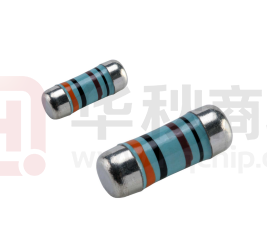
MELF TYPE METAL FILM RESISTORS, COATED TYPE
Feature
· Advanced thin film technology
· Excellent overall stability: Class 0.05%
· Extremely low TCR:
up to ±5ppm/K
· Exceptionally low noise and voltage coefficient
• Compliant to RoHS directive 2011/65/EU
• Compliant to REACH (EC No. 1907/2006)) (last updated: 27/06/2018)
Description
Production is strictly controlled and follows extensive set of instructions
established in production procedure for reproducibility. A homogeneous
film of metal alloy is deposited on the surface of high-grade ceramic cores
(85%~96% AL2O3) and conditioned to achieve the desired stability and the
temperature coefficients.
A professional laser or an extreme thin emery wheel is pressed on the
metalized rods to not only achieve the target value but also prefect
electronics performance by smoothly cutting a helical groove in the
resistance layer on the ceramic rods without damaging the ceramics.
The resistance layers are covered by a protective coating and hard
Bakelite designed for electrical, mechanical, and climatic protection.
The resistors are tested in accordance with MIL-R-10509F which refers to
MIL- STD-202 or IEC60115.
The established reliability in accordance with CECC 40401-803
Version E is available upon request.
www.thunder-resistor.com
sales@thunder-resistor.com
1
�1. PRODUCT: METAL FILM MELF TYPE PRECISION RESISTORS
2. PART NUMBER: Part number of the melf type precision metal film resistor is
identified by the series name, power rating, metric size code, resistance
tolerance, temperature coefficient, packing type and resistance value.
For example:
RJM
Series
Name
73P
Power
rating
0204
Size
code
B
Tolerance
6
TCR
T
Packing
Style
5051
Resistance
Value
(1) Series name: RJM series
(2) Power rating listed in the Electric characteristics
M= Tiny size; P= power mode; S= Small size; “ “= normal size
(3) Metric size: DIN: 0102, DIN: 0204, DIN: 0207, DIN: 0411, DIN: 0617
(4) Tolerance: W=±0.05%; B=±0.1%; C=±0.25%; D=±0.5%; F=±1%; G=±2%
(5) T.C.R.:
7≤ ±5ppm/℃; 6≤ ±10ppm/℃; 5≤ ±15ppm/℃; 3=±25ppm/℃;
2≤ ±50ppm/℃; 1≤±100ppm/℃; 0≤±200ppm/℃
(6) Packaging Type: B=BULK/BOX
T=REEL/BOX
(7) Resistance Value: 100K(1003); 22K5(2252); 2K15(2151);120R(1200);
10R(10R0); 1.8R(1R80); 0.99R(R990)………
(9)
RJM73P020400TR000 and RJM74P020700TR000 are jumpers with
resistance lower than 15mΩ
3. Structure of the resistors:
www.thunder-resistor.com
sales@thunder-resistor.com
2
�4. COLOR BAND-CODE:
Four color bands codes for size 0102 and 0204.
Five color bands for size 0207, 0411, 0516
www.thunder-resistor.com
sales@thunder-resistor.com
3
�5.
*
ELECTRICAL CHARACTERISTICS
Unless otherwise specified, all values are tested at the following condition
Temperature: 21℃ to 25℃; Relative humidity: 45% to 70%;
The parts must be well soldering with good soldering pads.
Power Rating X Resistance Value
*
Rated Continuous Working Voltage (RCWV)=
*
Resistance value out of range is available on request.
*
The post high temperature treatment after final tin plating is strictly controlled by
our production procedure to minimize the tin whisker phenomenon
*
The resistances of all jumpers are lower than 15mΩ
www.thunder-resistor.com
sales@thunder-resistor.com
4
�6. Derating curves
The power dissipation on the resistor generates a temperature rise against
the local ambient, depending on the heat flow support of the printed-circuit
board (thermal resistance). The rated dissipation applies only if the permitted
film temperature is not exceeded. These resistors do not feature a limited
lifetime when operated within the permissible limits. However, resistance
value drift increasing over operating time may result in exceeding a limit
acceptable to the specific application, thereby establishing a functional
lifetime.
For MELF resistors working at an
ambiance temperature of 70 ℃ or
above, the power rating shall be
derated in accordance with the above
curves.
7. Pulse load capability
www.thunder-resistor.com
sales@thunder-resistor.com
5
�8. ENVIRONMENTAL CHARACTERISTICS
(1) Temperature Coefficient Test
IEC 60115-1, 4.8: Test of resistors at room temperature and 60°C (or 100°C
upon request) above room temperature. Then measure the resistance. The
Temperature Coefficient is calculated by the following equation and its value
should be within the range requested.
R = Resistance value under the testing
R0= Resistance value at the room temperature
t = the 2nd testing temperature
t0 = Room temperature
(2) Short Time Overload Test
IEC60115-1 4.13: At 2.5 times rated voltage or 2 times the maximum working
voltage whichever is lower for 5 seconds, the resistor should be free from
defects. The change of the resistance value of normal size resistors should be
within ±(0.1%+0.05Ω) and within ±(0.2%+0.05Ω) for tiny size resistors as
compared with the value before the test.
(3) Solderability
IEC 60115-1, 4.17: 255±5°C for 3±0.5 Seconds, there are at least 90% solder
coverage on the termination.
(4) Resistance to soldering heat:
IEC 60115-1, 4.18: 260±3°C for 10±1 Seconds, immersed only the cap into tin
bath. The change of the resistance value should be within ±(0.15%+0.1Ω) as
compared with the value before the test.
(5) Rapid change of temperature (Thermal shock)
IEC 60115-1, 4.19: 30 min at LCT; 30 min at UCT; LCT = -55°C; UCT = 125°C.
5 cycle from LCT to room temperature. and to UCT and to room temperature.
The change of the resistance value shall be within ±(0.25%+0.05Ω) for the
resistors of tight tolerance and normal size; should be within ±(1%+0. 05Ω) for
resistors of normal tolerance and tiny size as compared with the value before
the load.as compared with the value before the load.
www.thunder-resistor.com
sales@thunder-resistor.com
6
�(6) Damp Heat Steady State
IEC 60115-1, 4.24: 40±2°C, 90-95% RH for 56 days, loaded with 0.1 times
RCWV or the maximum working voltage whichever is lower.
The change of the resistance value should be within ±(0.25%+0. 05Ω) for
resistors with tight tolerance and normal size and should be within ±(1%+0. 05Ω)
for resistors with normal tolerance and tiny size as compared with the value
before the load.
(7) Load Life Test
IEC 60115-1, 4.25: 70±2°C at RCWV or the maximum working voltage
whichever is lower for 1,000+48/-0 Hr. (1.5Hr. on, 0.5Hr. off). The resistors
shall be arranged not much effected mutually by the temperature of others
and the excessive ventilation shall not be performed.
The change of the resistance value should be within ±(0.25%+0.05Ω) for
resistors with tight tolerance and normal size and should be within ± (1%+0.05Ω)
for resistors with normal tolerance and tiny size as compared with the value
before the load.
(8) Endurance at upper category temperature
IEC60115-1, 4.25.3: put resistors in over with temperature at 125 °C for 1000h.
The change of the resistance value should be within ±(0.25%+0. 05Ω) for
resistors with tight tolerance and within ±(1%+0. 05Ω) for resistors with normal
tolerance and tiny size as compared with the value before the load.
(9) Accidental Overload Test
IEC 60115-1, 4.26: 4 times RCWV or 2 times the maximum working voltage
whichever is lower for 1 Minute. No evidence of flaming or arcing.
(10) Component solvent resistance
IEC 60115-1, 4.29: Isopropyl alcohol; 50 °C; method 2. No visible damage.
(11) Solvent resistance of marking
IEC 60115-1, 4.30: Isopropyl alcohol; 50 °C; method 1, toothbrush. Marking
legible; no visible damage
www.thunder-resistor.com
sales@thunder-resistor.com
7
�(12) Resistance to Solvent
IEC 60115-1, 4.30: IPA for 5±0.5 Min. with ultrasonic. Marking legible; no visible
deterioration occurred.
(13) Damp heat, steady state, accelerated
IEC 60115-1, 4.37: (85 ± 2)°C, (85 ± 5)% RH; U = 0.3 x RCWV or U = 0.3 x
Umax or 100V whichever is lower for 120 hours.
The change of the resistance value should be within ±(0.25%+0. 05Ω) for
resistors with tight tolerance and within ±(1%+0. 05Ω) for resistors with
normal tolerance and tiny size as compared with the value before the load.
(14) Electrostatic discharge (Human Body Model)
IEC 60115-1, 4.38: IEC 61340-3-1 (1); 3 pos. + 3 neg. discharges.
RJM72P0102: 1.5kV; RJM73P0204: 2kV; RJM74P0207: 3kV;
RJM16M0207: 3 kV;
RJM17M0411: 4kV; RJM18M0617: 6kV
The change of the resistance value should be within ±(0.50%+0. 05Ω) as compared
with the value before the load.
Disclaimer
All products, product specifications and data are subject to change
without notice to improve reliability, function, design or otherwise.
Thunder Precision Resistors makes no warranty, representation or
guarantee regarding the suitability of the products for any particular
purpose or the continuing production of any product to the maximum
extent permitted by applicable law.
www.thunder-resistor.com
sales@thunder-resistor.com
8
�


 工商网监
湘ICP备2023018690号
工商网监
湘ICP备2023018690号
