LoRa® Technology Evaluation
Suite User’s Guide
2016 Microchip Technology Inc.
DS40001847A
�Note the following details of the code protection feature on Microchip devices:
•
Microchip products meet the specification contained in their particular Microchip Data Sheet.
•
Microchip believes that its family of products is one of the most secure families of its kind on the market today, when used in the
intended manner and under normal conditions.
•
There are dishonest and possibly illegal methods used to breach the code protection feature. All of these methods, to our
knowledge, require using the Microchip products in a manner outside the operating specifications contained in Microchip’s Data
Sheets. Most likely, the person doing so is engaged in theft of intellectual property.
•
Microchip is willing to work with the customer who is concerned about the integrity of their code.
•
Neither Microchip nor any other semiconductor manufacturer can guarantee the security of their code. Code protection does not
mean that we are guaranteeing the product as “unbreakable.”
Code protection is constantly evolving. We at Microchip are committed to continuously improving the code protection features of our
products. Attempts to break Microchip’s code protection feature may be a violation of the Digital Millennium Copyright Act. If such acts
allow unauthorized access to your software or other copyrighted work, you may have a right to sue for relief under that Act.
Information contained in this publication regarding device
applications and the like is provided only for your convenience
and may be superseded by updates. It is your responsibility to
ensure that your application meets with your specifications.
MICROCHIP MAKES NO REPRESENTATIONS OR
WARRANTIES OF ANY KIND WHETHER EXPRESS OR
IMPLIED, WRITTEN OR ORAL, STATUTORY OR
OTHERWISE, RELATED TO THE INFORMATION,
INCLUDING BUT NOT LIMITED TO ITS CONDITION,
QUALITY, PERFORMANCE, MERCHANTABILITY OR
FITNESS FOR PURPOSE. Microchip disclaims all liability
arising from this information and its use. Use of Microchip
devices in life support and/or safety applications is entirely at
the buyer’s risk, and the buyer agrees to defend, indemnify and
hold harmless Microchip from any and all damages, claims,
suits, or expenses resulting from such use. No licenses are
conveyed, implicitly or otherwise, under any Microchip
intellectual property rights unless otherwise stated.
Trademarks
The Microchip name and logo, the Microchip logo, AnyRate,
dsPIC, FlashFlex, flexPWR, Heldo, JukeBlox, KeeLoq,
KeeLoq logo, Kleer, LANCheck, LINK MD, MediaLB, MOST,
MOST logo, MPLAB, OptoLyzer, PIC, PICSTART, PIC32 logo,
RightTouch, SpyNIC, SST, SST Logo, SuperFlash and UNI/O
are registered trademarks of Microchip Technology
Incorporated in the U.S.A. and other countries.
ClockWorks, The Embedded Control Solutions Company,
ETHERSYNCH, Hyper Speed Control, HyperLight Load,
IntelliMOS, mTouch, Precision Edge, and QUIET-WIRE are
registered trademarks of Microchip Technology Incorporated
in the U.S.A.
Analog-for-the-Digital Age, Any Capacitor, AnyIn, AnyOut,
BodyCom, chipKIT, chipKIT logo, CodeGuard, dsPICDEM,
dsPICDEM.net, Dynamic Average Matching, DAM, ECAN,
EtherGREEN, In-Circuit Serial Programming, ICSP, Inter-Chip
Connectivity, JitterBlocker, KleerNet, KleerNet logo, MiWi,
motorBench, MPASM, MPF, MPLAB Certified logo, MPLIB,
MPLINK, MultiTRAK, NetDetach, Omniscient Code
Generation, PICDEM, PICDEM.net, PICkit, PICtail,
PureSilicon, RightTouch logo, REAL ICE, Ripple Blocker,
Serial Quad I/O, SQI, SuperSwitcher, SuperSwitcher II, Total
Endurance, TSHARC, USBCheck, VariSense, ViewSpan,
WiperLock, Wireless DNA, and ZENA are trademarks of
Microchip Technology Incorporated in the U.S.A. and other
countries.
SQTP is a service mark of Microchip Technology Incorporated
in the U.S.A.
Microchip received ISO/TS-16949:2009 certification for its worldwide
headquarters, design and wafer fabrication facilities in Chandler and
Tempe, Arizona; Gresham, Oregon and design centers in California
and India. The Company’s quality system processes and procedures
are for its PIC® MCUs and dsPIC® DSCs, KEELOQ® code hopping
devices, Serial EEPROMs, microperipherals, nonvolatile memory and
analog products. In addition, Microchip’s quality system for the design
and manufacture of development systems is ISO 9001:2000 certified.
QUALITY MANAGEMENT SYSTEM
CERTIFIED BY DNV
== ISO/TS 16949 ==
DS40001847A-page 2
Silicon Storage Technology is a registered trademark of
Microchip Technology Inc. in other countries.
GestIC is a registered trademarks of Microchip Technology
Germany II GmbH & Co. KG, a subsidiary of Microchip
Technology Inc., in other countries.
All other trademarks mentioned herein are property of their
respective companies.
© 2016, Microchip Technology Incorporated, Printed in the
U.S.A., All Rights Reserved.
ISBN: 978-1-5224-0549-8
2016 Microchip Technology Inc.
�Object of Declaration: LoRa® Technology Evaluation Suite
2016 Microchip Technology Inc.
DS40001847A-page 3
�LoRa® Technology Evaluation Suite User’s Guide
NOTES:
DS40001847A-page 4
2016 Microchip Technology Inc.
�LoRa® TECHNOLOGY EVALUATION SUITE
USER’S GUIDE
Table of Contents
Preface ........................................................................................................................... 9
Chapter 1. Getting Started With The LoRa® Suite
1.1 Suite Overview ............................................................................................. 15
1.2 Document Terminology ................................................................................ 15
1.3 Suite Objectives ........................................................................................... 18
1.4 Utility Description .......................................................................................... 20
1.5 Utility Behavior ............................................................................................. 20
1.6 Utility Layout and Navigation ........................................................................ 21
1.6.1 Navigation Menu ....................................................................................... 21
1.6.2 Find Devices .............................................................................................. 22
1.6.3 Device List ................................................................................................ 22
1.6.4 Model View Panel ...................................................................................... 23
1.6.5 Utility Console ........................................................................................... 23
Chapter 2. Installation
2.1 Overview ...................................................................................................... 25
2.2 Features ....................................................................................................... 25
2.3 Installation Instructions ................................................................................. 26
2.3.1 Installation Process ................................................................................... 26
2.3.2 Component Selection ................................................................................ 28
2.3.2.1 Applications ............................................................................... 28
2.3.2.2 Server Application ..................................................................... 28
2.3.2.3 Redistributables ......................................................................... 28
2.3.3 Installation Finalization .............................................................................. 28
2.3.4 Uninstallation ............................................................................................. 31
2.3.5 Installing Java Redistributable RE8 ........................................................... 32
2.3.6 Installing Docker Toolbox .......................................................................... 35
Chapter 3. System Preparation
3.1 Launch Oracle VM VirtualBox ...................................................................... 39
3.2 Add Port Forwarding Rules for Oracle VM VirtualBox Manager .................. 40
3.3 Assign Static IP ............................................................................................ 43
Chapter 4. Server Setup
4.1 Launch Docker Quickstart Terminal ............................................................. 47
4.2 Load Docker Image ...................................................................................... 48
4.3 View Docker Image ...................................................................................... 49
4.4 Create Docker Container .............................................................................. 49
4.5 Start Container ............................................................................................. 50
4.6 Stop Container ............................................................................................. 50
4.7 Restart Container ......................................................................................... 51
4.8 Docker Documentation ................................................................................. 51
2016 Microchip Technology Inc.
DS40001847A-page 5
�LoRa® Technology Evaluation Suite User’s Guide
Chapter 5. Network Evaluation Kit Setup
5.1 Connect LoRa Technology Devices ............................................................. 53
5.2 Connect Devices to LoRa Development Utility ............................................. 54
5.3 Configure Gateway ....................................................................................... 55
5.4 Configure RN Module for Auto-Create Personalization ................................ 56
5.5 Add Server to Device List ............................................................................. 58
5.6 Connect Utility to MySQL IP Address ........................................................... 59
Chapter 6. Additional Setup for Operation at 915 MHz
6.1 Configure RN Module for 8 Channels .......................................................... 61
6.2 Issue Unconfirmed Dummy Uplink ............................................................... 64
6.3 Change Gateway Region ............................................................................. 65
Chapter 7. Auto-Create Example Implementation
7.1 Issue Unconfirmed Uplink Using Auto-Create Personalization .................... 67
7.2 Confirm Gateway Capture ............................................................................ 68
7.3 View Uplink Message in Database ............................................................... 69
Chapter 8. Activation-By-Personalization (ABP) Example Implementation
8.1 Create Provisioned (ABP) Credentials for Server ........................................ 71
8.2 Confirm ABP Addition in Database .............................................................. 74
8.3 Save ABP Credentials to RN Module ........................................................... 76
8.4 Join Using ABP Credentials ......................................................................... 77
8.5 Issue Unconfirmed Uplink Using ABP Personalization ................................ 79
8.6 Confirm Gateway Capture ............................................................................ 80
8.7 View Uplink in Database .............................................................................. 82
Chapter 9. Over-The-Air Example Implementation
9.1 Create a New Application Inside the Server ................................................. 85
9.2 Create OTAA Credentials in Server Application ........................................... 87
9.3 Confirm Server Application Addition to Database ........................................ 89
9.4 Confirm OTAA Device Addition to Database ................................................ 90
9.5 Save OTAA Credentials to RN Module ........................................................ 92
9.6 Join Server Using OTAA Credentials ........................................................... 93
9.7 Issue Unconfirmed Uplink Using OTAA Personalization .............................. 94
9.8 Confirm Gateway Capture ............................................................................ 95
9.9 View Uplink in Database .............................................................................. 97
Chapter 10. Queue Downlink For an End Device
10.1 Queue Downlink ......................................................................................... 99
Chapter 11. Receiving Queued Downlink Messages
11.1 Reconfigure RN Module for ABP .............................................................. 103
11.2 Issue Confirmed Uplink ............................................................................ 104
11.3 Observe Downlink Response ................................................................... 105
Chapter 12. RN Modules
12.1 Overview .................................................................................................. 107
12.2 Features ................................................................................................... 107
12.3 Description ............................................................................................... 108
DS40001847A-page 6
2016 Microchip Technology Inc.
�12.3.1 LoRaWAN Tab Descriptions .................................................................. 108
12.3.2 RN Module Channel Tab Descriptions .................................................. 127
12.3.3 RN Module FCC Tab Descriptions ........................................................ 133
12.3.4 RN Module Radio Tab Descriptions ...................................................... 154
12.3.5 RN Module Device Firmware Update (DFU) Tab Descriptions ............. 173
Chapter 13. Gateways
13.1 Overview .................................................................................................. 179
13.2 Features ................................................................................................... 179
13.3 Description ............................................................................................... 179
13.3.1 Gateway Tab Descriptions .................................................................... 180
Chapter 14. Gateway Behavior Operation
14.1 Overview .................................................................................................. 197
14.2 Power and Communication Connections ................................................. 197
14.2.1 USB ....................................................................................................... 197
14.2.2 Ethernet ................................................................................................. 197
14.3 Interaction, Navigation, and Display ......................................................... 197
14.4 Commands ............................................................................................... 200
14.5 General Application Description ............................................................... 208
14.6 Gateway Configuration ............................................................................. 211
14.7 SD Card Configuration ............................................................................. 212
14.8 Bootloader and Firmware Updates ........................................................... 213
Chapter 15. LoRa® Technology Server and Database
15.1 Overview .................................................................................................. 217
15.2 Features ................................................................................................... 217
15.3 Description ............................................................................................... 217
15.3.1 Server Tab Description .......................................................................... 218
15.3.2 Database Tab Description ..................................................................... 230
15.3.3 Data Traffic Table Description ............................................................... 233
15.3.4 Application Servers Table Description ................................................... 237
15.3.5 Gateway Units Table Description .......................................................... 238
15.3.6 ABP Devices Table Description ............................................................. 243
15.3.7 OTAA Devices Table Description .......................................................... 246
Worldwide Sales and Service .................................................................................. 249
2016 Microchip Technology Inc.
DS40001847A-page 7
�LoRa® Technology Evaluation Suite User’s Guide
NOTES:
DS40001847A-page 8
2016 Microchip Technology Inc.
�LoRa® TECHNOLOGY EVALUATION SUITE
USER’S GUIDE
Preface
NOTICE TO CUSTOMERS
All documentation becomes dated, and this manual is no exception. Microchip tools and
documentation are constantly evolving to meet customer needs, so some actual dialogs and/
or tool descriptions may differ from those in this document. Please refer to our website
(www.microchip.com) to obtain the latest documentation available.
Documents are identified with a “DS” number. This number is located on the bottom of each
page, in front of the page number. The numbering convention for the DS number is
“DSXXXXXXXXA”, where “XXXXXXXX” is the document number and “A” is the revision level
of the document.
For the most up-to-date information on development tools, see the MPLAB® IDE online help.
Select the Help menu, and then Topics to open a list of available online help files.
INTRODUCTION
This chapter contains general information that will be useful to know when using the
Microchip LoRa™ Technology Network Evaluation Kit. Topics discussed in this chapter
include:
•
•
•
•
•
•
•
Document Layout
Conventions Used in this Guide
Recommended Reading
The Microchip website
Development Systems Customer Change Notification Service
Customer Support
Revision History
DOCUMENT LAYOUT
This document describes how to use the LoRa® Technology Evaluation Kit along with
the LoRa Development Utility Application Graphic User Interface (GUI) as a
demonstration platform to show how to create and manage a LoRa Technology
Network. The document is organized as follows:
• Chapter 1. “Getting Started With The LoRa® Suite” – This chapter describes
the layout of the LoRa Technology Development Utility, menu navigation,
terminology, device models, and general operation details.
• Chapter 2. “Installation” – This chapter describes the contents of the LoRa
Technology Development Suite Installation Package, basic requirements and
uninstallation process.
• Chapter 3. “System Preparation”– This chapter describes the process of
configuring Oracle® VM Virtual Box Port Forwarding, and configuring a static IP
address.
• Chapter 4. “Server Setup” – This chapter describes how to use docker to
manage the LoRa Evaluation server.
2016 Microchip Technology Inc.
DS40001847A-page 9
�LoRa® Technology Evaluation Suite User’s Guide
• Chapter 5. “Network Evaluation Kit Setup” – This chapter describes how to
connect the LoRa Evaluation Kit boards to the Utility and configure parameter
settings.
• Chapter 6. “Additional Setup for Operation at 915 MHz” – This chapter
describes how to configure the Mote for eight channels of operation, and change
the operating region of the Gateway.
• Chapter 7. “Auto-Create Example Implementation” – This chapter describes
how to connect a Mote to the Evaluation server using the Auto-Create form of
Personalization.
• Chapter 8. “Activation-By-Personalization (ABP) Example Implementation”
– This chapter describes how to connect a Mote to the Evaluation server using the
Activation-By-Personalization.
• Chapter 9. “Over-The-Air Example Implementation” – This chapter describes
how to create a server Application and connect a Mote to the Evaluation server
through use of the new Application and Over-The-Air Activation (OTAA).
• Chapter 10. “Queue Downlink For an End Device” – This chapter describes
how to queue a Downlink Message for response to a joined Mote upon next
confirmed Uplink.
• Chapter 11. “Receiving Queued Downlink Messages” – This chapter
describes how to view the received Downlink.
• Chapter 12. “RN Modules” – This chapter goes into full detail of navigating the
RN Module model view, discussing each interactive element, method of use and
coordinating effect.
• Chapter 13. “Gateways” – This chapter goes into full detail of the Gateway
model view, discussing each interactive element, method of use and coordinating
effect.
• Chapter 14. “Gateway Behavior Operation” – This chapter describes the
communication methods, setup, configuration and the hardware requirements for
getting started with the LoRa Technology infrastructure.
• Chapter 15. “LoRa® Technology Server and Database” – This chapter goes
into full detail of both tab options within the Server model view, discussing each
interactive element, method of use and coordinating effect.
DS40001847A-page 10
2016 Microchip Technology Inc.
�Preface
CONVENTIONS USED IN THIS GUIDE
This manual uses the following documentation conventions:
DOCUMENTATION CONVENTIONS
Description
Arial font:
Italic characters
Initial caps
Quotes
Underlined, italic text with
right angle bracket
Bold characters
N‘Rnnnn
Text in angle brackets < >
Courier New font:
Plain Courier New
Represents
Referenced books
Emphasized text
A window
A dialog
A menu selection
A field name in a window or
dialog
A menu path
MPLAB® IDE User’s Guide
...is the only compiler...
the Output window
the Settings dialog
select Enable Programmer
“Save project before build”
A dialog button
A tab
A number in verilog format,
where N is the total number of
digits, R is the radix and n is a
digit.
A key on the keyboard
Click OK
Click the Power tab
4‘b0010, 2‘hF1
Italic Courier New
Sample source code
Filenames
File paths
Keywords
Command-line options
Bit values
Constants
A variable argument
Square brackets [ ]
Optional arguments
Curly brackets and pipe
character: { | }
Ellipses...
Choice of mutually exclusive
arguments; an OR selection
Replaces repeated text
Represents code supplied by
user
2016 Microchip Technology Inc.
Examples
File>Save
Press ,
#define START
autoexec.bat
c:\mcc18\h
_asm, _endasm, static
-Opa+, -Opa0, 1
0xFF, ‘A’
file.o, where file can be
any valid filename
mcc18 [options] file
[options]
errorlevel {0|1}
var_name [,
var_name...]
void main (void)
{ ...
}
DS40001847A-page 11
�LoRa® Technology Evaluation Suite User’s Guide
RECOMMENDED READING
This user’s guide describes the contents and uses of the LoRa Technology Development
Suite. Other useful documents are listed below. The following Microchip documents are
available and recommended as supplemental reference resources:
LoRa® Mote User’s Guide (DS40001808)
This user’s guide describes how the LoRa Mote demonstration board is used with the
LoRa Technology RN Modules.
RN2483 Low-Power Long-Range LoRa® Technology Transceiver Module Data
Sheet (DS50002346)
This data sheet provides detailed specifications for the RN2483 module.
RN2483 LoRa® Technology Module Command Reference User’s Guide
(DS40001784)
This user’s guide provides specifications about the commands to be used with the
LoRa module.
RN2483 LoRa® Technology PICtail™/PICtail Plus Daughter Board User’s Guide
(DS50002366)
This user’s guide describes how to configure and use the LoRa Daughter Board.
RN2903 Low-Power Long-Range LoRa® Technology Transceiver Module Data
Sheet (DS50002390)
This data sheet provides detailed specifications for the RN2903 module.
RN2903 LoRa® Technology Module Command Reference User’s Guide
(DS40001811)
This user’s guide provides specifications about the commands to be used with the
LoRa module.
RN2903 LoRa® Technology PICtail™/PICtail Plus Daughter Board User’s Guide
(DS50002424)
This user’s guide describes how to configure and use the LoRa Daughter Board.
To obtain any of Microchip’s documents, visit the Microchip website at
www.microchip.com.
THE MICROCHIP WEBSITE
Microchip provides online support via our website at www.microchip.com. This website
is used as a means to make files and information easily available to customers. Accessible by using your favorite Internet browser, the website contains the following information:
• Product Support – Data sheets and errata, application notes and sample
programs, design resources, user’s guides and hardware support documents,
latest software releases and archived software
• General Technical Support – Frequently Asked Questions (FAQs), technical
support requests, online discussion groups, Microchip consultant program
member listing
• Business of Microchip – Product selector and ordering guides, latest Microchip
press releases, listing of seminars and events, listings of Microchip sales offices,
distributors and factory representatives
DS40001847A-page 12
2016 Microchip Technology Inc.
�Preface
DEVELOPMENT SYSTEMS CUSTOMER CHANGE NOTIFICATION SERVICE
Microchip’s customer notification service helps keep customers current on Microchip
products. Subscribers will receive e-mail notification whenever there are changes,
updates, revisions or errata related to a specified product family or development tool of
interest.
To register, access the Microchip website at www.microchip.com, click on Customer
Change Notification and follow the registration instructions.
The Development Systems product group categories are:
• Compilers – The latest information on Microchip C compilers, assemblers, linkers
and other language tools. These include all MPLAB C compilers; all MPLAB
assemblers (including MPASM™ assembler); all MPLAB linkers (including
MPLINK™ object linker); and all MPLAB librarians (including MPLIB™ object
librarian).
• Emulators – The latest information on Microchip in-circuit emulators.This
includes the MPLAB REAL ICE™ and MPLAB ICE 2000 in-circuit emulators.
• In-Circuit Debuggers – The latest information on the Microchip in-circuit
debuggers. This includes MPLAB ICD 3 in-circuit debuggers and PICkit™ 3
debug express.
• MPLAB® X IDE – The latest information on Microchip MPLAB IDE, the Windows®
Integrated Development Environment for development systems tools. This list is
focused on the MPLAB IDE, MPLAB IDE Project Manager, MPLAB Editor and
MPLAB SIM simulator, as well as general editing and debugging features.
• Programmers – The latest information on Microchip programmers. These include
production programmers such as MPLAB REAL ICE in-circuit emulator, MPLAB
ICD 3 in-circuit debugger and MPLAB PM3 device programmers. Also included
are nonproduction development programmers such as PICSTART® Plus and
PICkit 2 and 3.
CUSTOMER SUPPORT
Users of Microchip products can receive assistance through several channels:
•
•
•
•
Distributor or Representative
Local Sales Office
Field Application Engineer (FAE)
Technical Support
Customers should contact their distributor, representative or field application engineer
(FAE) for support. Local sales offices are also available to help customers. A listing of
sales offices and locations is included in the back of this document.
Technical support is available through the website at:
http://www.microchip.com/support.
REVISION HISTORY
Revision A (May 2016)
Initial release of the document.
2016 Microchip Technology Inc.
DS40001847A-page 13
�LoRa® Technology Evaluation Suite User’s Guide
NOTES:
DS40001847A-page 14
2016 Microchip Technology Inc.
�LoRa® TECHNOLOGY EVALUATION SUITE
USER’S GUIDE
Chapter 1. Getting Started With The LoRa® Suite
1.1
SUITE OVERVIEW
The LoRa® Technology Evaluation Suite is an installation package that includes all
necessary components for evaluation of an example LoRa system. Included in the
Suite is the LoRa Development Utility, ‘mchplora’ example server Docker™ Image,
and Java™ 1.8 Runtime Redistributable.
Working through the objects outlined in this document will teach the three methods of
network admittance used by Motes: auto-create, personalization, over-the-air. Server
applications will be discussed, along with queuing downlink response messages.
The LoRa Technology Development Utility is intended to be used with Microchip’s
LoRa Network Evaluation Kit. It can additionally be used along with Microchip’s
stand-alone LoRa development tools, or custom-created products/prototypes capable
of USB-to-serial communication with the RN Module, necessary for command
processing.
The ‘mchplora’ example server Docker Image file is supplied to offer an out-of-box
capable example server. Use of the example server requires a third-party open source
program, not included in the LoRa Suite installation package. Refer to
Section 2.3.6 “Installing Docker Toolbox” for additional information.
1.2
DOCUMENT TERMINOLOGY
Because of the complex nature of this system, there are key phrases and keywords
used throughout this document which may not be familiar.
Listed below are keywords that may be encountered throughout the documents:
Docker
• Docker Toolbox – Installs Docker Client, Machine, Compose and Kitematic;
available for both Windows® and MAC®. Refer to: https://www.docker.com/products/docker-toolbox.
What’s in the Toolbox:
- Docker Engine
- Docker Compose
- Docker Machine
- Docker Kitematic
- Docker Quickstart Terminal
- Oracle® VM Virtual Box
• Docker Engine – A lightweight runtime and robust tooling that builds and runs
Docker containers. Runs on Linux® to create the operating environment for
distributed applications. The in-host Daemon communicates with the Docker
client to execute commands to build, ship and run containers. Refer to:
htpps://www.docker.com/products/docker-engine.
• Docker Compose – Allows multi-container applications with all its dependencies
to be defined into a single file, spinning the application up into a single command.
Refer to: https://www.docker.com/products/docker-compose.
2016 Microchip Technology Inc.
DS40001847A-page 15
�LoRa® Technology Evaluation Suite User’s Guide
• Docker Machine – Tool used to install Docker Engine on virtual host, and
manage host with commands. Requires the use of Oracle Virtual Box; on
Windows and MAC installation of Docker Toolbox, will automatically install Virtual
Box. Refer to: https://docs.docker.com/machine/.
• Docker Kitematic – A simple, yet powerful graphic user interface, created to run
containers. This application is not used for this user’s guide. Refer to:
https://kitematic.com/.
• Docker Quickstart Terminal – This is a terminal emulation program which allows
access to the Docker Engine; used on Windows and MAC operating systems.
This is not required for Linux users, as the Docker Engine can be accessed
directly through Linux Terminal navigation.
• Virtual Machine – Emulation of a particular computer system. Operates based
upon computer architecture, with functions of a real or hypothetical computer.
Implementations may work with specialized software, hardware, or a combination
of both.
• Oracle VM Virtual Box – Virtual Machine program installed along with the Docker
Toolbox for use with Docker Machine. Refer to: https://www.oracle.com/technetwork/server-storage/virtualbox/overview/index.html.
• Image – The basis of containers. A read-only template used by Docker for repositories. Refer to: https://docs.docker.com/engine/userguide/containers/dockerimages/.
• Container – Active repository uncompressed from a Docker Image. Containers
are created from image files with an added read-write file system layer, and can
be run in isolation.
Utility
• Device Model – Collection of variables capable of being context-saved, used to
define an object.
Utility Device Models:
- RN Module
- Gateway
- Server
- COM
• Model View Controller – A software design pattern useful for implementing user
interfaces on a computer. Used to separate internally represented information
from the way the information is presented. For example, storage of date
information e.g., 1/1/2015 vs displayed method of: January 1, 2015. Useful for
GUI development; it is often referred to as a Model View.
Utility Model Views:
- RN Module – Chapter 12. “RN Modules”
- Gateway – Chapter 13. “Gateways”
- Server – Chapter 15. “LoRa® Technology Server and Database”
- COM – Chapter 12. “RN Modules”
• Titled Pane – Panel with a title that can be collapsed; opened, and closed.
• Panel – The simplest container class; provides space in which an application can
attach any other component, including other panels.
• Scroll Panel – Provides a horizontal or vertical scrollable view of a component.
When screen real estate is limited, a scroll pane can be used to display a
component that is large, or one whose size can change dynamically.
• Text Field – Text component object which allows the editing of a single line of
text.
DS40001847A-page 16
2016 Microchip Technology Inc.
�Getting Started With The LoRa® Suite
• Combo Box – A drop-down field containing a specific list of possible values
available to a variable configuration. The combo boxes used with the utility are not
editable.
• Radio Button – An item that can be selected or deselected, and which displays
its state. Used for Boolean variable configuration within the utility.
• Push Button – Object used to initiate an action or event when pressed.
• Tabs – Collection of panels organized into sections for display by the Model View.
• Table View – Designed to visualize an unlimited number of rows of data, broken
out into descriptive columns.
• Polling – Periodic, or repeating action of requesting or waiting for information.
Utility Validators
• Hex – A value lead with the distinguishing characters “0x”; must be between
0 – F.
FIGURE 1-1:
HEX VALIDATOR
Invalid Input
Valid Input
• Decimal – A numerical value; must be 0 – 9.
FIGURE 1-2:
DECIMAL VALIDATOR
Valid Input
Invalid Input
• String (ANCII) – Characters such a letters, numbers, symbols (0-9, A-Z, a-z,
!@#$, etc..).
FIGURE 1-3:
ANCII VALIDATOR
Valid Input
• IP – (4-12) decimal value representing an Internet Protocol Address
(0.0.0.0 – 255.255.255.255).
FIGURE 1-4:
IP VALIDATOR
Valid Input
Note:
2016 Microchip Technology Inc.
Invalid Input
Numerical range depends on Device Model variable. Text and field boards
will be shown in blue if entered text is valid in format and range, otherwise
the field will be shown in red. Refer to Chapter 12. “RN Modules”,
Chapter 13. “Gateways”, and Chapter 15. “LoRa® Technology Server
and Database” for more detail.
DS40001847A-page 17
�LoRa® Technology Evaluation Suite User’s Guide
LoRa
• Evaluation Server – LoRa Server supplied with the LoRa Suite, packaged into
Image file
- Network Server – Server that maintains a record for each Mote.
- Application Server – Server responsible for admitting OTA Motes to the
network and for encrypting user data sent to, and decrypting user data
received from the Mote. A single Application Server may be connected to
many network and customer servers. The remote server or controller used for
a given Mote is determined by the application to which the Mote is assigned.
- Customer Server – A trivial implementation of the program used by the data
owner to receive Mote data.
- Network Controller – Receives transmission parameters used by the Mote
and characteristics of the signal received by the gateway for each frame. It
may perform operations using that data. For the provided Evolution server,
only Automatic Data Rate (ADR) control for a Mote is available for use.
• Server Application – Custom Created (OTA) Application operating within the
Evaluation Server
• Mote – The End Device of a LoRa Network.
• Gateway – Device responsible for forwarding date between Motes and a single
LoRa network server.
• Uplink – Issuing a LoRaWAN™ Transmission from an End Device to a Gateway
• Downlink – Issuing a LoRaWAN Transmisison from a Gateway to an End Device
• Upstream – Data exchanged between Gateway and Server
• Downstream – Data exchanged between Server and Gateway
1.3
SUITE OBJECTIVES
The purpose of the LoRa Technology Development Suite User’s Guide is to outline all
steps necessary to use the material supplied to operate the LoRa Evolution Network.
Further exploration and development of a LoRa system through use of the evaluation
server should be simple upon completion of the objectives outlined this guide.
Below are the objectives:
•
•
•
•
•
•
•
•
•
•
Installation
System Preparation
Server Setup
Network Evaluation Kit Setup
Operation at 915 MHz
Auto-Create
Activation-By-Personalization (ABP)
Over-The-Air (OTA)
Queue Downlink Messages
Receiving Downlink Message
A LoRa system can be implemented in many different ways. Operation of the
evaluation system discussed in this document will be configured as shown in
Figure 1-5. For this configuration the LoRa Technology Evaluation Kit will be used.
DS40001847A-page 18
2016 Microchip Technology Inc.
�Getting Started With The LoRa® Suite
FIGURE 1-5:
LoRa® NETWORK EVALUATION SETUP
(64-bit) Windows®, MAC® Operating System Computer
Oracle® Virtual Machine
Port
Forwarding
DockerTM Engine
Port:
3306
lora_server
-p -p
mchplora
LAN
Static IP
192.168.1.1
Port:
1700
JavaTM Runtime
Environment
Development
Utility
TCP/IP
Drivers
USB
Drivers
Ethernet
Connector
USB
Connector
USB
USB
Ethernet
Core
Board
G
Radio
Board
LoRa®
RN Module
Populated
Mote / PICtailTM
The LoRa Gateway board, consisting of the Core board, and Radio board attachment,
is connected to the Host PC through USB, supplying both power and Serial
communication. Additionally, an Ethernet cable is connected between the Core board
and the PC’s Local Area Network (LAN) connector; this is used for communication
between Gateway and Server.
The RN Module populated development board (Mote or PICtail™/PICtail Plus) is
connected to the same computer through its own USB connection, supplying both
power and Serial communication.
From the Host PC, the program Docker Toolbox will be used. Using the Docker Toolbox
allows the Oracle® Virtual Machine to operate, hosting the Docker Engine used to run
the LoRa evaluation server. A static IP address is assigned to the LAN adapter settings,
allowing for Gateway Traffic to be forwarded through the PC (1700) port to the Docker
hosted evaluation server.
The LoRa Development Utility runs within the Java Runtime Environment. From the
Utility commands and configurations, it can be issued from the PC to connected LoRa
Technology Evaluation Kit boards. Database information is exchanged between the
LoRa Utility and Docker-hosted evaluation server, through MySQL traffic (3306) port
forwarding.
2016 Microchip Technology Inc.
DS40001847A-page 19
�LoRa® Technology Evaluation Suite User’s Guide
1.4
UTILITY DESCRIPTION
Use of the Development Utility requires installation of Java 1.8 Runtime Environment.
Refer to Section 2.3.5 “Installing Java Redistributable RE8”.
The Development Utility has been written in a threaded manner, and thus each Device
Model instance runs independently. This allows for the user to operate all devices
populated in the list parallel to one another.
For example, it is possible to be doing a bootloader operation to multiple Mote units
simultaneously.
In addition, this allows for periodic data-request commands to be issued even when a
device is not actively selected from the Device List.
For example, a Gateway that is populated in the Device List is currently polling
statistical information, updating its Device Model variables. This will be processed by
the Utility even when the Server is selected from the Device List, and its model view
displays database information.
The Utility has been developed to support all commands capable of being issued, or
received by Microchip’s LoRa Gateway and RN Module devices; presented in an
easy-to-follow visual user interface allowing for configuration/modifications, without
knowledge of the command syntax. Additionally, the Utility is capable of exercising
advanced script-driven test, or polling actions. Furthermore, the Utility abstracts and
handles all MySQL communications with database and JSON communication with the
evaluation server. Refer to Chapter 12. “RN Modules”, Chapter 13. “Gateways”,
and Chapter 15. “LoRa® Technology Server and Database” for more advanced
descriptions of each Device Model and its features.
1.5
UTILITY BEHAVIOR
The Development Utility can be launched
‘LoRaDevUtility.jar’ executable file located
directory, Applications folder. The Utility supports
Models, based upon the device type. Each Device
used for layout navigation. The Utility maintains its
where all device interactions are displayed.
by double clicking on the
in the LoRa Suite installation
three different possible Device
Model uses its own Model View
own dedicated General Console
Upon launch, the Development Utility will initiate a scan for all available enumerated
USB COM ports. Once finding an available COM port, the application will request the
connected devices version information by issuing the string command sys get ver
with appropriate [ \r\n ] terminators added to conform with format
expected by Microchip LoRa Gateway, RN Module devices.
Based upon the response message, the device is created as either a RN Module or
Gateway, and is added to the Device List. If the incorrect or no response is received as
a response from the device, it is considered to be a non-LoRa device, and is not added
to the list. Devices selected in the list are each supported by their own Device Model,
each with its own threaded Context Switched Model View; allowing for each device to
maintain its own Console display, along with variable values.
At the top of the Utility is a simple context sensitive menu. The menu is used to remove
Gateway or RN Module units from the Device List. It can additionally be used to either
add or remove a Server Instance; only a single server is allowed in the Device List. A
more detailed description of the Utility Menu is given in Section 1.6.1 “Navigation
Menu”.
DS40001847A-page 20
2016 Microchip Technology Inc.
�Getting Started With The LoRa® Suite
1.6
UTILITY LAYOUT AND NAVIGATION
The layout for the Development Utility is divided as represented in Figure 1-6.
FIGURE 1-6:
LoRa® TECHNOLOGY UTILITY DEFAULT LAYOUT
1.6.1
Navigation Menu
The Utility Menu supplies a simple method of device removal, and has context
behaviors. For instance, the Gateway menu option is disabled unless a Gateway
device is currently selected from the list.
Below is a list of the available menu options, and expected behavior conditions:
• File
- Close
Exits the Device Utility. This does not affect server status.
• Module
- Bootloader Recovery
Scans and populates the Device List with all currently available COM ports
without distinguishing if the connected device is a Microchip LoRa Technology
product. This is intended to be used with RN Modules which received the sys
erase FW command, but do not yet have updated application code. Refer to
Section 12.3.5 “RN Module Device Firmware Update (DFU) Tab
Descriptions” for more detail.
- Remove
Remove the currently selected RN Module from the Device List. Parameter value
entered in the text fields will be lost if not previously issued to the RN Module
device.
2016 Microchip Technology Inc.
DS40001847A-page 21
�LoRa® Technology Evaluation Suite User’s Guide
• Gateway
- Remove
Remove the currently selected Gateway from the Device List. Parameter value
entered in the text fields will be lost if not previously issued to the Gateway device.
• Server
- Add
Create a Server Device instance to be populated on the Device List.
Docker needs to be installed and running the Server container for full-feature of the
Server Device Model. Refer to Chapter 3. “System Preparation” and Chapter
4. “Server Setup” for additional information.
- Remove
Remove the Server instance from the Device List.
This action will have no effect on the Docker-run Server/Database. Parameter values
entered in the text fields will be lost if not previously issued to the SQL database.
• About
- Help
Print to the General Console the latest build information details for the LoRa
Development Utility.
1.6.2
Find Devices
The Device Scanner button is used to detect and add newly attached Microchip LoRa
Technology devices to the list. Pressing the Find LoRa Devices button will result in the
command sys get ver being issued to all available enumerated COM ports available
to the application. All devices will respond to this command with board-specific
information.
Example of expected responses:
• Gateway: Microchip LoRa Gateway Version 0.1.2
• RN Module: RN2903 0.9.5 Sep 02 2015 17:22:00
1.6.3
Device List
The Device List is populated either when the application is launched, or upon pressing
the scan button. Once valid devices are found, their appropriate models are created,
and a distinguishing name is given to populate the list. The Device List can be cleared
through the stand method of device removal discussed within this user’s guide.
Below are the Device Models capable of populating the list:
• RN Module – Development board, or end product populated with the LoRaWAN
protocol capable module.
• Gateway – Development board created to communicate with LoRaWAN protocol
capable end devices.
• Server – Supplied model view used to communicate with the evaluation Server,
along with SQL database management. The Device List may only contain a single
instance of a Server device.
• COM – Under special conditions, all available COM ports are scanned and
populate to the Device List. Only the Device Firmware Update (DFU) tab will be
available to COM device types. Operation of the DFU tab from the COM Device
Model is the same as when being used from the RN Module. Refer to
Section 12.3.5 “RN Module Device Firmware Update (DFU) Tab
Descriptions” for additional details.
DS40001847A-page 22
2016 Microchip Technology Inc.
�Getting Started With The LoRa® Suite
1.6.4
Model View Panel
The model viewer panel is populated with the appropriate model based upon the
currently selected device inside the list. Each model view and layout is dependent upon
the device type, a unique console displaying actions or commands performed by the
device.
Refer to Chapter 12. “RN Modules”, Chapter 13. “Gateways”, and Chapter
15. “LoRa® Technology Server and Database” for more advanced descriptions of
each Device Model, and its features.
1.6.5
Utility Console
The Development Utility general console is used to maintain a log of all created and
destroyed devices. Clicking on the Clear Log push button inside the console
(Figure 1-6), will remove all previous dialogue messages.
2016 Microchip Technology Inc.
DS40001847A-page 23
�LoRa® Technology Evaluation Suite User’s Guide
NOTES:
DS40001847A-page 24
2016 Microchip Technology Inc.
�LoRa® TECHNOLOGY EVALUATION SUITE
USER’S GUIDE
Chapter 2. Installation
2.1
OVERVIEW
The LoRa Technology Development Suite is used to install all necessary components
to get a LoRa Technology Network system up and running. This includes the
Development Utility, which was developed specifically to help allow the user to fully
evaluate, develop, and implement a LoRa Technology Application, with use of the LoRa
Network Evaluation Kit.
The intention of the LoRa Technology Development Suite is to supply a single package
capable of making the introduction of running a LoRaWAN network easy.
An example LoRa server with database wrapped inside a Docker Image is
included with the suite. This allows operation of a LoRaWAN network out of box, along
with the use of Docker and the LoRa Development Utility.
Included with the suite is a copy of Java Runtime Environment RE8, which is required
to be installed prior to the use of the LoRa Technology Development Utility. Additionally,
the open-source third party program Docker is required for local Server/Database use.
The installer Docker Toolbox is not included with the suite, but can be acquired free of
cost from: www.docker.com.
Through use of Microchip’s LoRa Technology Network Evaluation Kit, the user is
capable of running the evaluation LoRa Technology Network without writing a single
line of code, and only minimal configuration. Microchip’s LoRa Gateway boards (core
and RF) are used to capture Uplink Messages issued by end devices, such as
Microchip’s LoRa Mote or LoRa PICtail boards. To help in forming a better
understanding of the LoRa System, all material required has been included with the
LoRa Development Suite.
2.2
FEATURES
Windows, Apple® and Linux-based operating systems each have their own particular
Installation Suites.
By default, all suite contents will be selected for installation, however the user can
specify the desired content. The full contents of the LoRa Development Suite
Installation Package are shown below:
• Applications
- Development Utility
- HID Bootloader (Windows supported only)
• Server Applications
- Docker Server/Database Evaluation Image
• Redistributables
- Java Runtime Environment 8.65 (64-bit; OS specific)
2016 Microchip Technology Inc.
DS40001847A-page 25
�LoRa® Technology Evaluation Suite User’s Guide
2.3
INSTALLATION INSTRUCTIONS
Select the installer package of the desired platform from the www.microchip.com/lora
website. Once downloaded, launch the installer by double clicking the LoRa
Technology Development Suite Installation. After a few moments, a splash screen will
appear followed by the initial Setup page, see Figure 2-1.
FIGURE 2-1:
2.3.1
INSTALLATION LAUNCH
Installation Process
Following this screen will be Microchip’s License Agreement, which must be accepted
to proceed, see Figure 2-2.
FIGURE 2-2:
DS40001847A-page 26
LICENSE AGREEMENT
2016 Microchip Technology Inc.
�Installation
After agreeing to the License Agreement, a specific directory for installation can be
selected by clicking on the Browse Directory Icon ( ). This will prompt the user,
requesting a directory location, see Figure 2-3.
FIGURE 2-3:
SELECT DIRECTORY
By default, the installation directory is Microchip\LoRaSuite. Once an installation
directory has been specified, the user will be able to select which files to install, see
Figure 2-4.
FIGURE 2-4:
2016 Microchip Technology Inc.
INSTALLATION COMPONENT SELECTION
DS40001847A-page 27
�LoRa® Technology Evaluation Suite User’s Guide
2.3.2
Component Selection
Below are listed the selectable contents of the Installation package:
2.3.2.1
APPLICATIONS
Development Utility
The Development Utility is intended to be used with the full Network Evaluation Kit. The
Development Utility can connect and configure the Gateway, Mote, PICtail and RN
Module design capable of serial command communication. Additionally, it can be used
to manage the evaluation LoRa server and Database. The Utility is useful evaluation of
a simple, but full LoRa Technology Network.
2.3.2.2
SERVER APPLICATION
Docker Server/Database Evaluation Image
This Image file has been compiled to supply a Docker Hosted LoRa Technology
Server/Database evaluation platform. Through Docker, this image can be turned into a
container, used to fully demonstrate an evaluation server, with minimal actions required
by the user.
2.3.2.3
REDISTRIBUTABLES
Java Run Time Environment 8
This is the standard redistributable RE file supplied through Java for redistribution:
http://www.oracle.com/technetwork/java/javase/downloads/index.html.
2.3.3
Installation Finalization
After selecting the desired components, the process will prompt a final confirmation for
installation, see Figure 2-5.
FIGURE 2-5:
DS40001847A-page 28
INSTALLATION CONFIRMATION
2016 Microchip Technology Inc.
�Installation
An installer process indicator will be shown as the files are unpackaged, see
Figure 2-6.
FIGURE 2-6:
INSTALL PROCESS BAR
Upon completion of installation, see Figure 2-7, the user will be given the option to view
the latest Readme file, see Figure 2-8. This Readme file is used to describe any recent
changes or additions made to the LoRa Development Suite.
FIGURE 2-7:
2016 Microchip Technology Inc.
INSTALLATION FINALIZATION
DS40001847A-page 29
�LoRa® Technology Evaluation Suite User’s Guide
FIGURE 2-8:
INSTALLER README
Contents of the installation can be found in the specified directory, and a folder will be
added to the Start menu, see Figure 2-9.
FIGURE 2-9:
DS40001847A-page 30
UNINSTALLER
2016 Microchip Technology Inc.
�Installation
2.3.4
Uninstallation
Execution of the Uninstaller will completely remove all contents unpackaged during the
installation process at the specified directory. The Uninstaller will not remove any
additional material loaded on the user’s computer, including those installed by the
redistributors. A single prompt message will appear, confirming the desire to uninstall
the LoRa Technology Development Suite and all of its modules, see Figure 2-10.
FIGURE 2-10:
CONFIRM UNINSTALL
Once confirmed, it will take a short amount of time to remove the contents. A progress
bar is used to indicate the status. After completion a pop-up box will appear indicating
the uninstallation is completed, see Figure 2-11.
FIGURE 2-11:
UNINSTALL COMPLETION
2016 Microchip Technology Inc.
DS40001847A-page 31
�LoRa® Technology Evaluation Suite User’s Guide
2.3.5
Installing Java Redistributable RE8
Java 8 is required to be installed on the PC for use of the Development Utility. Included
with the suite is a copy of the Java Runtime RE8 redistributable (64-bit); it can be found
in the installation directory within the Java folder. Start the installation by executing the
jre-8u65-windows-x64.exe (Windows), jre-8u65-macosx-x64.dmg (MAC),
jre-8u65-linux-x64.rpm (Linux).
The installer may ask security permission to run, followed by the Welcome screen (see
Figure 2-12). From the Welcome screen the installation can begin, or a custom
installation destination folder can be specified (Figure 2-13).
DS40001847A-page 32
FIGURE 2-12:
JAVA™ SETUP WELCOME
FIGURE 2-13:
JAVA™ INSTALLATION DIRECTORY
2016 Microchip Technology Inc.
�Installation
The installation of the Java Runtime Environment 8.65 by Oracle will take a short time
(see Figure 2-14).
FIGURE 2-14:
JAVA™ INSTALLATION
If a previous version of Java is already installed on the computer, after completion the
installer will ask if an uninstallation of old version is required (see Figure 2-15).
FIGURE 2-15:
2016 Microchip Technology Inc.
OUT-OF-DATE UNINSTALLATION
DS40001847A-page 33
�LoRa® Technology Evaluation Suite User’s Guide
Completion of the Java 8 installation will bring up a final prompt window (see
Figure 2-16).
FIGURE 2-16:
DS40001847A-page 34
JAVA™ INSTALLATION COMPLETION
2016 Microchip Technology Inc.
�Installation
2.3.6
Installing Docker Toolbox
Installation of the Docker Toolbox application is required for use of running the
evaluation
servers
included
with
the
suite.
Go
to
the
website
https://www.docker.com/products/docker-toolbox to download a copy.
It is recommended to follow the Docker Toolbox Get Started Process.
• Windows: https://docs.docker.com/windows/
• Mac: https://docs.docker.com/mac/
• Linux: https://docs.docker.com/linux/
The installer may ask security permission to run, followed by the Setup screen (see
Figure 2-17). It is recommended that a full installation is done, however a custom installation can be performed. The use of Kinematic and Git are not required.
FIGURE 2-17:
DOCKER™ TOOLBOX SETUP
Before installation can complete, the Docker Toolbox will request a final configuration
request (see Figure 2-18). It is recommended to check Add docker binaries to PATH,
as well as Upgrade Boot2Docker VM, for best experience.
FIGURE 2-18:
2016 Microchip Technology Inc.
ADDITIONAL TASK
DS40001847A-page 35
�LoRa® Technology Evaluation Suite User’s Guide
A final review of the installation description is given prior to installation execution (see
Figure 2-19).
FIGURE 2-19:
SUMMARY
The Docker Toolbox will take a short time. The desired installation directory cannot be
specified (see Figure 2-20).
FIGURE 2-20:
TOOLBOX INSTALLATION
Upon successful installation, the prompt window will request if shortcuts should be
shown upon completion (see Figure 2-21).
DS40001847A-page 36
2016 Microchip Technology Inc.
�Installation
FIGURE 2-21:
2016 Microchip Technology Inc.
INSTALLATION COMPLETION
DS40001847A-page 37
�LoRa® Technology Evaluation Suite User’s Guide
NOTES:
DS40001847A-page 38
2016 Microchip Technology Inc.
�LoRa® TECHNOLOGY EVALUATION SUITE
USER’S GUIDE
Chapter 3. System Preparation
3.1
LAUNCH ORACLE VM VIRTUALBOX
Purpose
Oracle VM VirtualBox runs the Docker Engine, which is required for server operation.
Objectives
• Execute Oracle VM VirtualBox Manager (Figure 3-1)
FIGURE 3-1:
ORACLE® VM VIRTUALBOX MANAGER
Description
On 64-bit Windows and 64-bit Mac OS, Docker runs from within a Virtual Machine
through Oracle VirtualBox, which is installed along with the Docker Toolbox; Docker
runs natively on 64-bit Linux systems. For Windows and MAC it will also be necessary
to forward Port traffic settings. This can be done using the Oracle VM VirtualBox
Manager tool. Figure 3-1 shows what this may look like after a clean installation.
2016 Microchip Technology Inc.
DS40001847A-page 39
�LoRa® Technology Evaluation Suite User’s Guide
3.2
ADD PORT FORWARDING RULES FOR ORACLE VM VIRTUALBOX
MANAGER
Purpose
This allows the PC to forward all Gateway and Database Traffic to the default virtual
machine where the evaluation Server/Database is running.
Objectives
• Select default virtual machine from available list (Figure 3-2)
FIGURE 3-2:
DEFAULT VIRTUAL MACHINE
• Go to Settings (Figure 3-3)
FIGURE 3-3:
DS40001847A-page 40
VIRTUAL MACHINE SETTINGS
2016 Microchip Technology Inc.
�System Preparation
• Select Network (see Figure 3-4)
FIGURE 3-4:
NETWORK TAB
• Press Port Forwarding button (see Figure 3-5)
FIGURE 3-5:
2016 Microchip Technology Inc.
NETWORK ADVANCED SETTINGS
DS40001847A-page 41
�LoRa® Technology Evaluation Suite User’s Guide
• Press icon to Add Port Forwarding Rule (Figure 3-6)
• Create first Rule as described below (Figure 3-6):
- Name: Gateway Traffic
- Protocol: UDP
- Host IP:
- Host Port: 1700
- Guest IP:
- Guest Port: 1700
• Press icon to Add Port Forwarding Rule (Figure 3-6)
• Create second Rule as described below (Figure 3-6):
- Name: MySQL Traffic
- Protocol: TCP
- Host IP:
- Host Port: 3306
- Guest IP:
- Guest Port: 3306
• - Press icon to Add Port Forwarding Rule (Figure 3-6)
• - Create third Rule as described below (Figure 3-6):
- Name: Customer Server Traffic
- Protocol: UDP
- Host IP:
- Host Port: 5000
- Guest IP:
- Guest Port: 5000
FIGURE 3-6:
PORT FORWARDING RULES
• Close all Oracle VM Virtual Box Windows
DS40001847A-page 42
2016 Microchip Technology Inc.
�System Preparation
Description
Select the default virtual machine and then go to Settings. This can be done from the
menu at the top, or by right clicking and selecting it. Figure 3-5 shows the locations.
From the Settings Menu select the Network Tab, next press the Port Forwarding
push button. This will bring up a Port Forwarding Rules breakout window; two new rules
will be created by clicking on the Add File icon. The naming does not matter, but should
be meaningful for the user.
For our example, name the first rule Gateway Traffic. Leave the Host IP and Guest IP
blank, to allow reception of all network traffic. Set the Host Port and Guest Port to 1700.
Name the second rule MySQL Traffic. Again, leave the IPs blank; this time set the Ports
to 3306. Name the third rule Customer Server Traffic. Again, leave the IPs blank; this
time set the Ports to 5000.
3.3
ASSIGN STATIC IP
Purpose
This configures the PC to use a static IP address for it Local Area Network (LAN)
Ethernet connection.
Objectives
• Open Control Panel (Figure 3-7)
• Network Status and Task (Figure 3-7)
FIGURE 3-7:
2016 Microchip Technology Inc.
CONTROL PANEL
DS40001847A-page 43
�LoRa® Technology Evaluation Suite User’s Guide
• Change Adaptor Settings (Figure 3-8)
FIGURE 3-8:
DS40001847A-page 44
NETWORK STATUS AND TASKS
2016 Microchip Technology Inc.
�System Preparation
• Configure PC Local Area Network (LAN) Connection Properties (Figure 3-9)
FIGURE 3-9:
LOCAL AREA (LAN) CONNECTION
• Configure Internet Protocol Version 4 (TCP/IPv4) Properties (Figure 3-10)
FIGURE 3-10:
2016 Microchip Technology Inc.
LAN PROPERTIES
DS40001847A-page 45
�LoRa® Technology Evaluation Suite User’s Guide
• Select Use the following Settings (Figure 3-11)
• Configure fields as shown below (Figure 3-11):
- IP Address: 192.168.1.1
- Subnet Mask: 255.255.255.0
• Click OK to save settings (Figure 3-11)
FIGURE 3-11:
INTERNET PROTOCOL VERSION 4 (TCP/IPV4) PROPERTIES
• Exit all other Setting windows
Description
Since the Gateway unit will be connected directly to the Host PC, where the Server
container is being run, we must first assign the PC as static IP address. This can be
done by going to the network settings.
For Windows, go to the Control Panel. Under Network and Internet is View network
status and tasks, as seen in Figure 3-7.
From the Network and Internet display, select Change adapter settings (Figure 3-8)
to bring up available network connections (Figure 3-9).
From the available connections, find Local Area Connection, right click and go to
properties. Navigate the scroll bar inside the properties window and find Internet
Protocol Version 4 (TCP/IPv4) and select properties (see Figure 3-10).
Inside the Internet Protocol Version 4 (TCP/IPv4) Properties settings (Figure 3-11),
select Use the following IP address. Make the IP Address match that used by the
Server IP used by the Gateway. By default this value is: 192.168.1.1. Assign a Subnet
Mask; by default this is: 255.255.255.0.
DS40001847A-page 46
2016 Microchip Technology Inc.
�LoRa® TECHNOLOGY EVALUATION SUITE
USER’S GUIDE
Chapter 4. Server Setup
4.1
LAUNCH DOCKER QUICKSTART TERMINAL
Purpose
Docker Terminal is used to communicate commands to Docker, which is used to run
the Evaluation Server/Database.
Objectives
• Launch Docker Quickstart Terminal application executable (Figure 4-1)
FIGURE 4-1:
DOCKER™ QUICKSTART TERMINAL
• Allow Docker Startup (Figure 4-2)
FIGURE 4-2:
DOCKER™ STARTUP
2016 Microchip Technology Inc.
DS40001847A-page 47
�LoRa® Technology Evaluation Suite User’s Guide
Description
Installed along with the LoRa Development Suite is a Docker Image created by
Microchip, containing an example LoRaWAN network, application, and customer
servers. On Windows, the image will be contained within the Docker folder, found inside
the specified LoRa Suite installation directory.
4.2
LOAD DOCKER IMAGE
Purpose
This command is used to load the Docker Image and prepare it for use.
Objectives
• Execute Docker Command (Figure 4-3)
Command
• docker load < /C/microchip/LoRaSuite/Docker/mchplora
Format
• docker load < [File Directory]
FIGURE 4-3:
LOAD AN IMAGE FILE
Description
Loading of the image can be done using the docker load command. Use of the
command requires pointing to the installation directory. Note that if the mapped
directory contains spaces, quotations are required, e.g., “Program Filed (x86)”.
Figure 4-3 gives an example of the load command when using the default Windows
installation directory. The command will take a short time to process.
DS40001847A-page 48
2016 Microchip Technology Inc.
�Server Setup
4.3
VIEW DOCKER IMAGE
Purpose
This command will show all current Image Repositories and details.
Objectives
• Execute Docker Command (Figure 4-4)
Command
• docker images
FIGURE 4-4:
VIEW IMAGE REPOSITORY INFORMATION
Description
Once the image has been loaded it will become available to the user through Docker
as a container. Review of available containers can be seen using the Image command.
Figure 4-4 shows this process in Docker.
4.4
CREATE DOCKER CONTAINER
Purpose
By issuing this command, the Container ‘lora_server’ is made using the Repository
Image ‘mchplora’, Tag version 1.1. This Container has an open UP/DOWN Port of
1700 for UDP traffic, and 3306 for TCP traffic.
Objectives
• Execute Docker Command (Figure 4-5)
Command
• docker create --name lora_server –p 1700:1700/UDP –p
3306:3306/TCP -p 5000:5000/UDP mchplora:1.1
Format
• docker create --name –p / :
FIGURE 4-5:
CREATE CONTAINER FROM IMAGE
2016 Microchip Technology Inc.
DS40001847A-page 49
�LoRa® Technology Evaluation Suite User’s Guide
Description
With the image available to Docker, it is now ready for a container to be created. Again,
this can be done through Docker, using the docker create command. This will
create the container with specific information for future use. It may take a small amount
of time for the container to be created. Once done, a Hex string representing the Image
ID will be displayed. Figure 4-5 shows the create command in use.
4.5
START CONTAINER
Purpose
By issuing this command, the Docker Container will begin to run.
Objectives
• Execute Docker Command (Figure 4-6)
Command
• docker start lora_server
Format
• docker start [Container]
FIGURE 4-6:
CONTAINER START
Description
Once the container is created, the server is able to be started through a simple Docker
command. The Container will continue to run, even if Docker Terminal and Oracle VM
Virtual Machine windows are closed.
4.6
STOP CONTAINER
Purpose
By issuing this command, the Docker Container will stop running.
Objectives
• Execute Docker Command (Figure 4-7)
Command
• docker stop lora_server
Format
• docker stop [Container]
FIGURE 4-7:
CONTAINER STOP
Description
Once the container is created, the server is able to be started through a simple Docker
command. This command, or computer shutdown are the only ways to end a Container
operation.
DS40001847A-page 50
2016 Microchip Technology Inc.
�Server Setup
4.7
RESTART CONTAINER
Purpose
By issuing this command, the Docker Container will stop running, and then begin to run
again. If the container is not currently running, this command will start it.
Objectives
• Execute Docker Command (Figure 4-8)
Command
• docker restart lora_server
Format
• docker restart [Container]
FIGURE 4-8:
CONTAINER RESTART
Description
Once the container is created, the server is able to be started through a simple Docker
command. It is sometime necessary to restart the evaluation server to allow completion
of configuration, or database additions.
4.8
DOCKER DOCUMENTATION
Purpose
Expand Docker knowledge past the scope that is required for this exercise.
Objectives
• Visit: https://docs.docker.com/
Description
This is the extent of interaction with Docker required for this chapter. For additional
information on Docker, its commands, and other advanced uses, refer to the official
documentation on the program website: www.docker.com.
2016 Microchip Technology Inc.
DS40001847A-page 51
�LoRa® Technology Evaluation Suite User’s Guide
NOTES:
DS40001847A-page 52
2016 Microchip Technology Inc.
�LoRa® TECHNOLOGY EVALUATION SUITE
USER’S GUIDE
Chapter 5. Network Evaluation Kit Setup
5.1
CONNECT LoRa TECHNOLOGY DEVICES
Purpose
USB connections are used to power boards, as well as supply Serial Communication
for command handling. Ethernet is used for Gateway Traffic with Server.
Objectives:
• Connect Gateway Core board to PC using USB cable (Figure 5-1)
• Connect Gateway Core board to PC LAN Port using Ethernet Cable (Figure 5-1)
• Connect RN Module populated Mote or PICtail to PC using USB cable
(Figure 5-1)
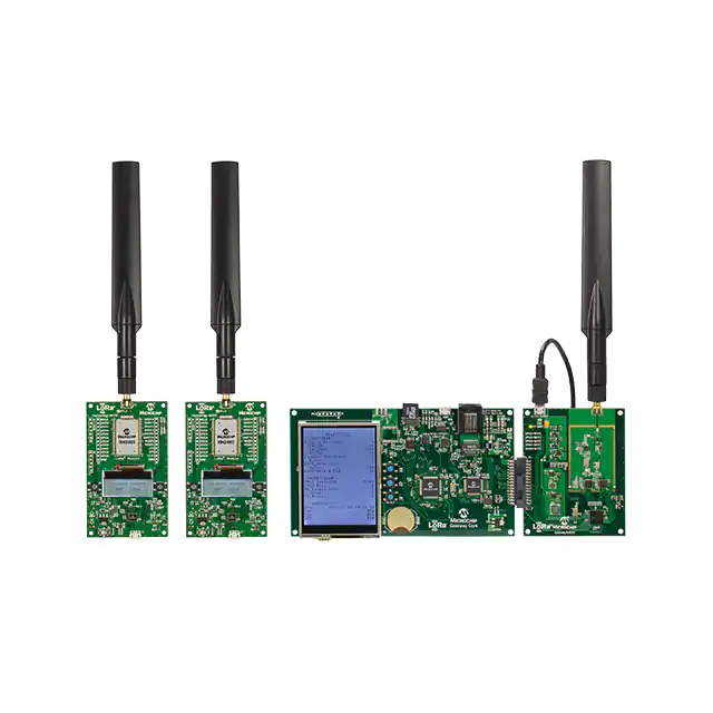
FIGURE 5-1:
NETWORK EVALUATION KIT
Description
With the LoRa Server container created and started, connect LoRa Network Evaluation
Kit boards to the Host PC. The use of the Development Utility will be required for the
remaining steps. Once all devices have been connected to the Host PC, launch the
Development Utility.
2016 Microchip Technology Inc.
DS40001847A-page 53
�LoRa® Technology Evaluation Suite User’s Guide
5.2
CONNECT DEVICES TO LoRa DEVELOPMENT UTILITY
Purpose
The Utility is used for demonstration of the LoRa Network Evaluation, making for easy
configuration and management of connected Gateway, or RN Module devices.
Objectives
• Launch LoRaDevUtility.jar (Figure 5-2)
• Allow devices to be scanned (Figure 5-2)
• Observe population of the Device List (Figure 5-2)
FIGURE 5-2:
DS40001847A-page 54
CONFIGURATION UTILITY
2016 Microchip Technology Inc.
�Network Evaluation Kit Setup
Description
Upon launch, the utility will scan for available LoRa devices. It will do so by first finding
available Serial COM ports, then issuing the sys get ver command. If either a RN
Module or Gateway Core board is connecting, it will respond with its version
information. This response is used to determine which type of Device Model will be
used by the utility for that designated COM port. If devices are connected after
launching the utility, simply press the Find LoRa Devices button, and all COM ports
will again be scanned. The use of a Gateway and RN Module End Device is required
for completion of this chapter. Figure 5-2 shows generally what the utility should look
like.
Note:
5.3
On Windows® computers it is sometimes required to disable COM Port
(COM3) to allow for proper communication with the Utility. This can be done
through the Device Manager, selecting Ports (COM and LPT); right click on
USB Serial Port (COM3) and select Disable.
CONFIGURE GATEWAY
Purpose
This is used to confirm Factory Programmed Default settings for the Gateway used for
this Network Evaluation demonstration. Confirms Communication between Server and
Gateway.
Objectives
• Select Gateway from Device List (Figure 5-3)
• Confirm Default Settings (Figure 5-3)
- Gateway ID: 0x1234567887654321
- IP Allocation Mode: Static
- Core Board IP: 192.162.1.101
- Network Router IP: 192.168.1.1
- Default Mask IP: 255.255.255.0
- LoRaWAN Operation: Enabled
- Forward Valid CRC: Checked (True)
- Forward Error CRC: Blank (False)
- Sync Word: 0x34
- LoRa Server IP: 192.168.1.1
- Server Up Port: 1700
- Server Down Port: 1700
- Keep Alive Interval: 10 (Seconds)
- Update Interval: 30 (Seconds)
- Polling Request Rate: 5 (Seconds)
• Start Polling Request (Figure 5-3)
• Observer [Online] Status (Figure 5-3)
2016 Microchip Technology Inc.
DS40001847A-page 55
�LoRa® Technology Evaluation Suite User’s Guide
FIGURE 5-3:
CONFIGURATION UTILITY
Description
Connect any of Microchip’s LoRa Development boards to the PC, using the included
USB cables. With the devices connected, browse to launch the LoRa Development
Utility as described in Chapter 1. “Getting Started With The LoRa® Suite”. After the
utility has been launched and the Device List is populated, confirm Gateway settings.
Select the Gateway from the utility Device List by clicking on the name. For this
chapter’s example system, we will be hosting a server locally from our PC at a Static
IP Address. The following settings for the Microchip LoRa Gateway board represent the
default parameter values, programmed at factory. It is recommended for this exercise
to use these values; with different values after completion of this chapter. The Ethernet
cable provided with the evaluation kit should be connected to the PC. With the cable
connected, and the server IP Address entered as 192.168.1.1, the user should be able
to observe an [Online] indicator on the LoRa Gateway LCD display. Figure 5-3 shows
these values displayed in the LoRa Development Utility.
5.4
CONFIGURE RN MODULE FOR AUTO-CREATE PERSONALIZATION
Purpose
This will allow for instant acceptance to the evaluation server.
Objectives
• Select RN Module from Device List (Figure 5-4)
• Select LoRaWAN Tab (Figure 5-4)
• Press Auto-Create Personalization push button (Figure 5-4)
DS40001847A-page 56
2016 Microchip Technology Inc.
�Network Evaluation Kit Setup
FIGURE 5-4:
CONFIGURE RN MODULE FOR AUTO-CREATE
• Observer configuration of parameters (Figure 5-5)
FIGURE 5-5:
2016 Microchip Technology Inc.
AUTOMATIC KEY ASSIGNMENT
DS40001847A-page 57
�LoRa® Technology Evaluation Suite User’s Guide
Description
With the LoRa Gateway connected to the Docker-run server, it is time to issue an Uplink
Message. Selecting the RN Module from the Device List, it will first connect to the
LoRaWAN network using the Auto-Create form of personalization. Under the initial tab
for the RN Module, LoRaWAN protocol, the user should select the ABP radio button
prior to pressing the Configure for Auto-Create Server button inside the Database
Authentication titled pane. This push button will preconfigure the device with specific
Network Session Key (0x2B7E151628A6ABF7158809CF4F3C), and Application
Session Key (0x3C8F262739BFE3B7BC0826991AD0504D) which have been
configured in the server to allow instant access. The Device Address will automatically
be filled in, using the lower eight bytes of the Hardware Extended-Unique-Identifier
(HwEUI). The module will automatically issue a SAVE, and JOIN command upon button
press.
This will configure Network Session Key as 0x2B7E151628A6ABF7158809CF4F3C,
and Application Session Key as 0x3C8F262739BFE3B7BC0826991AD0504D. These
credentials are used to grant instant access to the Server Network. Device Address is
generated from the RN Module’s lower eight bytes of the Hardware
Extended-Unique-Identifier (HwEUI).
5.5
ADD SERVER TO DEVICE LIST
Purpose
This populates a Server instance to the Device List.
Objectives
• Select Server from Utility menu (Figure 5-6)
• Select Add under Server menu (Figure 5-6)
FIGURE 5-6:
ADD SERVER
• Observe Server added to Device List (Figure 5-7)
FIGURE 5-7:
DS40001847A-page 58
SERVER IN DEVICE LIST
2016 Microchip Technology Inc.
�Network Evaluation Kit Setup
Description
With the Uplink Message successfully issued by the End Device, it is time to check and
see if the Server has successfully captured the transmission. This can be done using
the LoRa Development Utility Server Device Model view. To populate the Server
Device Model to the list, go to the top menu, click on Server and then add. This will add
a Server device to the Device List column, as shown in Figure 5-7. There can only be
a single server instance created at one time.
5.6
CONNECT UTILITY TO MySQL IP ADDRESS
Purpose
This connects the Utility to the MySQL database used with to manage evaluation server
data.
Objectives
• Enter 192.168.1.1 into MySQL IP Address text field (Figure 5-8)
FIGURE 5-8:
SUCCESSFUL CONNECTION
• Confirm Connection Status (Figure 5-9)
FIGURE 5-9:
SUCCESSFUL CONNECTION
Description
From the Server Device Model view, enter the server IP Address into the MySQL IP
Address text field. Press Enter on the key board while in the text field, or click on the
Connect to IP push button to set the value for the model. A timestamp message will
appear in the Server Console showing the new MySQL IP.
When not connected to a Server/Database, the Version will show “Not Connected”, as
seen in Figure 5-8. Once connected to the IP address, the correct Server Version will
be shown, as seen in Figure 5-9.
2016 Microchip Technology Inc.
DS40001847A-page 59
�LoRa® Technology Evaluation Suite User’s Guide
NOTES:
DS40001847A-page 60
2016 Microchip Technology Inc.
�LoRa® TECHNOLOGY EVALUATION SUITE
USER’S GUIDE
Chapter 6. Additional Setup for Operation at 915 MHz
6.1
CONFIGURE RN MODULE FOR 8 CHANNELS
Purpose
This will configure the RN Module to only issue LoRaWAN transmission on channels
0-7, which are the only channels supported by the Network Evaluation Kit Gateway.
Objectives
• Select RN Module, Confirm RN2903 module type (Figure 6-1)
FIGURE 6-1:
RN MODULE MAC CHANNELS
2016 Microchip Technology Inc.
DS40001847A-page 61
�LoRa® Technology Evaluation Suite User’s Guide
• Select MAC Channels Tab (Figure 6-2)
FIGURE 6-2:
MAC CHANNELS TAB
• Press Disable All Channels button (Figure 6-3)
FIGURE 6-3:
DS40001847A-page 62
DISABLE CHANNELS
2016 Microchip Technology Inc.
�Additional Setup for Operation at 915 MHz
• Press Enable 8 Channels button (Figure 6-4)
FIGURE 6-4:
ENABLE CHANNELS
Description
Prior to using the RN Module populated end devices with the Microchip Gateway, it is
necessary to configure the LoRaWAN Channels for use. By default the RN2483 868
MHz module has channels (0-2) enabled, leaving channels (3-15) disabled. For the
purpose of this Chapter’s exercise no changes are required. If using the RN2483, skip
to the next section.
The RN2903 915 MHz module has its full range of channels (0-63) enabled by default.
The Microchip Gateway Radio board is only capable of eight channels of operation. By
default it will use the lower eight channels; as a result, the RN2903 end-device
channels must be configured for use (Figure 6-1). This can quickly and easily be done
through the Utility by selecting the Module from the Device List, then selecting the
MAC Channels tab; seen in Figure 6-2.
When a LoRaWAN Uplink is issued from the End Device, it will do so only on the
enabled channels. So to ensure that only the desired channels will be used, first disable
all channels by pressing the Disable All Channels button, as seen in Figure 6-4. The
RN Module Console to the right will show the commands sent to the RN Module to
disable the channels.
By then using the Enable 8 Channels (Figure 6-4), only the lower eight channels will
be enabled. Again in the RN Module Console, the user can observe the RN Module
commands being sent. With this completed, the user can return to the LoRaWAN tab.
2016 Microchip Technology Inc.
DS40001847A-page 63
�LoRa® Technology Evaluation Suite User’s Guide
6.2
ISSUE UNCONFIRMED DUMMY UPLINK
Purpose
This allows the RN Module to send a LoRaWAN Uplink Message which the Gateway
will report. This allows the Gateway ID to be populated in the database inside the
Gateway Units table view.
Objectives
• Issue an Uplink from the RN Module (Figure 6-5)
• Select LoRaWAN Tab (Figure 6-5)
FIGURE 6-5:
RN MODULE SELECT
• Configure Uplink Packet Parameters (Figure 6-6)
- Port: 15
- Confirmed: Unchecked (False)
- ANCII: Unchecked (False)
- Payload: 0x01
• Press Transmit Uplink push button (Figure 6-6)
FIGURE 6-6:
DS40001847A-page 64
DUMMY UNCONFIRMED HEX DATA UPLINK
2016 Microchip Technology Inc.
�Additional Setup for Operation at 915 MHz
Description
After the device has joined the LoRaWAN network using the ABP Auto-Create form of
personalization, a first transmission can be issued. Under the Communication titled
pane in the LoRa MAC Control box, the Uplink settings and payload can be specified.
An Uplink Message can be issued on Port Numbers: 1-223; Data payloads must be in
Hex (0x).
String form is allowed when the ANCII checkbox is enabled. Once the Port number and
Payload have been provided, the user can issue the Uplink by pressing the Transmit
Uplink button. Figure 6-5 shows the key elements described in this section.
6.3
CHANGE GATEWAY REGION
Purpose
The server assumes all Gateway Units connecting are initially part of the 868 MHz
region (Region 4). This will change the Gateway from 868 MHz (Region 4) to 915 MHz
(Region 0). Proper Region settings are required by the Server.
Objectives
• Select Server from Device List (Figure 6-7)
• Select Database Tab (Figure 6-7)
• Select Gateway Units in combo box (Figure 6-7)
FIGURE 6-7:
GATEWAY UNITS DATABASE TABLE VIEW
• Select row containing Gateway ID: 0x123456788764321 (Figure 6-8)
• Click Region push button (Figure 6-8)
2016 Microchip Technology Inc.
DS40001847A-page 65
�CHANGE REGION
• Observe Region value change (Figure 6-9)
FIGURE 6-9:
REGION NUMERICAL REPRESENTATION
Description
If using the 868 MHz Gateway bandwidth, skip past this section to the next. By default Gateway Units are assumed to be
868 MHz by the server. Changing Region of operation for a Gateway Unit in the database is only required for 915 MHz
bandwidth.
When the Gateway received its first valid Uplink packet, it should have populated itself in the database. Return to the Server
Device Model, select the Database Tab. Use the combo box to select Database Table View, and choose Gateway Units
(Figure 6-7).
Select the Gateway Unit which is operating within the 915 MHz bandwidth, once selected the row will become highlighted in
blue. With the proper Gateway Row selected, press the Change Region push button; this button is only visible under
Gateway Unit table view. This will change the value stored in the Region column (Figure 6-8, Figure 6-9).
2016 Microchip Technology Inc.
Gateway Regions:
• 0 – 915 MHz
• 4 – 868 MHz
Previously, when the Gateway received the Uplink issued in Section 6.2 “Issue Unconfirmed Dummy Uplink”, it was still
considered to be a 868 MHz Gateway, and so the Server did not accept its packet from the 915 MHz bandwidth. With the
Region properly set for (0) 915 MHz bandwidth, return to the RN Module and again press Transmit Uplink to repeat the
previous Uplink Message. Now with the Gateway properly configured in the database, the packet will be processed.
LoRa® Technology Evaluation Suite User’s Guide
DS40001847A-page 66
FIGURE 6-8:
�LoRa® TECHNOLOGY EVALUATION SUITE
USER’S GUIDE
Chapter 7. Auto-Create Example Implementation
7.1
ISSUE UNCONFIRMED UPLINK USING AUTO-CREATE PERSONALIZATION
Purpose
This will issue a LoRaWAN unconfirmed Uplink Message from an End Device using
Auto-Create personalization keys.
Objectives
• Select RN Module configured in Section 5.4 “Configure RN Module for
Auto-Create Personalization”, from the Device List (Figure 7-1)
FIGURE 7-1:
AUTO-CREATE RN MODULE SELECTION
• Configure Uplink Packet Parameters (Figure 7-2)
- Port: 125
- Confirmed: Unchecked (False)
- ANCII: Checked (True)
- Payload: Auto-Create Uplink
• Press Transmit Uplink push button (Figure 7-2)
FIGURE 7-2:
ISSUE UNCONFIRMED AUTO-CREATE ASCII UPLINK
Description
After the device has joined the LoRaWAN network using the ABP Auto-Create form of
personalization, a first transmission can be issued. Under the Communication titled
pane in the LoRa MAC Control box the Uplink settings and payload can be specified.
An Uplink Message can be issued on Port Numbers: 1-223; Data payloads must be in
Hex (0x).
2016 Microchip Technology Inc.
DS40001847A-page 67
�LoRa® Technology Evaluation Suite User’s Guide
String form is allowed when the ANCII checkbox is enabled. Once the Port number and
Payload have been provided, the user can issue the Uplink by pressing the Transmit
Uplink button. Figure 7-2 shows the key elements described in this section.
7.2
CONFIRM GATEWAY CAPTURE
Purpose
This gives simple visual confirmation that the Gateway detected the Uplink.
Objectives
• Select Gateway from Device List (Figure 7-3)
FIGURE 7-3:
GATEWAY SELECTION
• Confirm Packets Received values has increased (Figure 7-4)
FIGURE 7-4:
DS40001847A-page 68
PACKETS RECEIVED DISPLAY
2016 Microchip Technology Inc.
�Auto-Create Example Implementation
Description
With the Gateway Polling Request running, a sys get report command is issued
from the Utility to the Gateway at the rate (in Seconds) specified through the text field.
Because the Utility is threaded, the Utility will request report information even if the
Gateway is not currently selected in the Device List.
7.3
VIEW UPLINK MESSAGE IN DATABASE
Purpose
This confirms that the Uplink Message was received by the Server, and was considered
valid.
Objectives
• Select Server from Device List (Figure 7-5)
• Select Database Tab (Figure 7-5)
• Select Application Data from combo box (Figure 7-5)
FIGURE 7-5:
DATA TRAFFIC
• Confirm Uplink information has been added to the database (Figure 7-6)
2016 Microchip Technology Inc.
DS40001847A-page 69
�DATA IN DATABASE
Description
With the MySQL IP Address configured, the LoRa Development Utility should now be able to gain access to the database.
In the Server Device Model, select the Database tab to view different table view displays. The table information is refreshed
upon use of the Database View combo box, tab selection, or automatically at the rate specified when Polling is enabled.
Figure 7-6 shows an example of the Application Data table which is populated with valid captured Uplink Messages, such
as the one sent in the previous section. All Uplink Messages transmitted by connected end devices, are displayed inside the
Application Data table, regardless of the method of personalization.
2016 Microchip Technology Inc.
LoRa® Technology Evaluation Suite User’s Guide
DS40001847A-page 70
FIGURE 7-6:
�LoRa® TECHNOLOGY EVALUATION SUITE
USER’S GUIDE
Chapter 8. Activation-By-Personalization (ABP) Example Implementation
8.1
CREATE PROVISIONED (ABP) CREDENTIALS FOR SERVER
Purpose
Create unique ABP Personalization credentials to the database.
Objectives
• Select Server from Device List (Figure 8-1)
FIGURE 8-1:
SERVER SELECTION
• Select Server Tab (Figure 8-2)
• Configure ABP Credentials Fields (Figure 8-2)
- Network Session Key (NwkSKey): 0x99
- Application Session Key (AppSKey): 0x87
- Device Address (DevAddr): 0x42
• Press Insert/Update to Database push button (Figure 8-2)
2016 Microchip Technology Inc.
DS40001847A-page 71
�LoRa® Technology Evaluation Suite User’s Guide
FIGURE 8-2:
PROVISIONED (ABP) DEVICE ADDITION
Description
Auto-Creation is a form of Activation-By-Personalization (ABP) network joining, used
for a very specific purpose. As previously discussed, for that method of
Personalization, Network Session Key (NwkSKey) and Application Session Key
(AppSKey) are shared across devices, with only the Device Address (DevAddr)
required to be unique. This allows for the ability to quickly and easily get a network
running, but is not the typical implementation of a Personalization Authentication
process.
Normally, when attempting to join a network through the ABP method, the Network
Session Key (NwkSKey) and Application Session Key (AppSKey) assigned to an End
Device are specific to the Device Address (DevAddr). This means that no two end
devices in the network should contain shared Network Session Key (NwkSKey) or
Application Session Key (AppSKey) values. Typically, the owner of a LoRa Server will
create and maintain a list of valid end devices allowed onto the network. This list
contains all unique Device Address, with unique Network Session Key, and Application
Session Key values predetermined and managed by the LoRa Server.
With the server running, the LoRa Development Utility makes it very simple to grant
network access to end devices. Addition of ABP devices can be completed through the
utility in two ways. The first method of adding a device can be done from the Server
Device Model, under the Server tab. For this process, the End Device is not required
to be connected to the utility. Under the End-Device Actions titled pane is the
Provisioned (ABP) titled pane. Contained inside are three text fields used to enter the
required Authentication keys, along with the Device Address assigned. Once the fields
have valid values entered, pressing the Insert/Update Device in Database push
button will issue the applicable MySQL commands to give the MySQL IP Address. This
will result in either an Insert, if the Device Address is new; or an Update if the Device
Address currently exists in the system and simply required Authentication Key
changes. Figure 8-3 and Figure 8-3 give an example of entering the information
necessary for a Provisioned device.
DS40001847A-page 72
2016 Microchip Technology Inc.
�Activation-By-Personalization (ABP) Example Implementation
FIGURE 8-3:
ZOOM ON PROVISIONED (ABP) ACCESS TITLED PANE
Addition of Provisioned (ABP) devices can also be done from the RN Module model
view from the LoRa Development Utility. This is used to grant instant access to end
devices physically connected to the same PC as the LoRa Development Utility. For
MySQL commands to be issued, the specified MySQL IP Address in the Database
Authentication titled pane must be valid. With all required Authentication parameter
values entered into the text fields, the LoRa Development Utility will issue the required
MySQL commands at the press of the Insert/Update to Database push button.
Figure 8-4 and Figure 8.2 give an example of how to add a Provisioned (ABP) device
from the RN Module model view.
FIGURE 8-4:
GRANTING PROVISIONED (ABP) ACCESS TO AN END DEVICE FROM SERVER
MODEL VIEW
2016 Microchip Technology Inc.
DS40001847A-page 73
�LoRa® Technology Evaluation Suite User’s Guide
8.2
CONFIRM ABP ADDITION IN DATABASE
Purpose
Confirms requested addition of ABP device was accepted and processed by the
Server.
Objectives
• Select Server from Device List (Figure 8-5)
FIGURE 8-5:
SERVER SELECTION
• Select Database Tab (Figure 8-6)
• Select ABP Devices from combo box (Figure 8-6)
FIGURE 8-6:
DS40001847A-page 74
ABP DEVICES TABLE VIEW
2016 Microchip Technology Inc.
�FIGURE 8-7:
ABP DEVICES ADDITION
Description
Once the MySQL message has been issued, the Server Console should contain a sentence describing its action, or it will
report MySQL connection issues. After attempting to grant access to a Provisioned (ABP) device, it can be confirmed by
entering the Server model in the LoRa Development Utility. Select the ABP Devices Database view from the combo box
under the Database tab, (Figure 8-6). This renders a table with all valid ABP Devices, including those connected using
Auto-Create, or the Provisioned (ABP) methods described above, (Figure 8-7).
DS40001847A-page 75
Activation-By-Personalization (ABP) Example Implementation
2016 Microchip Technology Inc.
• Confirm Added Credentials inside Table (Figure 8-7)
�LoRa® Technology Evaluation Suite User’s Guide
8.3
SAVE ABP CREDENTIALS TO RN MODULE
Purpose
Configure and Save ABP Authorization Keys to RN Module.
Objectives
• Select RN Module from Device List (Figure 8-8)
• Select LoRaWAN Tab (Figure 8-8)
FIGURE 8-8:
RN MODULE SELECTION
• Configure Server Authentication Keys (Figure 8-9)
- Network Session Key (NwkSKey): 0x99
- Application Session Key (AppSKey): 0x87
- Device Address (DevAddr): 0x42
• Press Save push button (Figure 8-9)
FIGURE 8-9:
DS40001847A-page 76
ABP AUTHENTICATION KEYS
2016 Microchip Technology Inc.
�Activation-By-Personalization (ABP) Example Implementation
Description
After creating new credentials for a valid Provisioned (ABP) end devices inside the
LoRa Server, it is necessary to issue a Restart, as discussed in Section 4.4 “Create
Docker Container”. This is a current limitation of the example server, and must be
done for all new additions.
Once creation of a new end-device credentials has been completed, the server will be
ready for communication. Confirmation of credentials can be done by finding device
information added to the ABP Devices Table View in the LoRa Development Utility. It is
now time to connect a RN Module populated End Device, and assign the newly created
authentication credentials for LoRaWAN network connection. The authentication
values can be assigned using the RN Module Device Model view. Under the LoRaWAN
tab is a titled pane titled Server/Database Requirements containing the Server
Authentication Keys titled pane. Here are the text fields where the user can specify the
new keys to be used for Provisioned Personalization. The user can either press Enter
in each text field to issue specific configuration commands individually. Or press the
Save button after entering values into the three required fields. If commands are sent
individually, it is still recommended to press the Save button to confirm RN Module
retention of the parameter values.
8.4
JOIN USING ABP CREDENTIALS
Purpose
This will allow the RN Module to perform LoRaWAN actions.
Objectives
• Select same RN Module from Section 8.3 “Save ABP Credentials to RN
Module”
• Select LoRaWAN Tab (Figure 8-10)
FIGURE 8-10:
RN MODULE SELECTION
• Press Join push button (Figure 8-11)
2016 Microchip Technology Inc.
DS40001847A-page 77
�LoRa® Technology Evaluation Suite User’s Guide
FIGURE 8-11:
JOIN USING ABP
Description
Once parameter values have been saved, the user can press Join to allow LoRaWAN
protocol. Figure 8-12 shows an example configuration of a RN Module using ABP
Personalization through the LoRa Development Utility.
FIGURE 8-12:
DS40001847A-page 78
JOINING A PROVISIONED (ABP) DEVICE
2016 Microchip Technology Inc.
�Activation-By-Personalization (ABP) Example Implementation
8.5
ISSUE UNCONFIRMED UPLINK USING ABP PERSONALIZATION
Purpose
This will issue an unconfirmed Uplink Message through use of unique ABP
credentials.
Objectives
• Select same RN Module from Section 8.4 “Join Using ABP
Credentials”
• Select LoRaWAN Tab (Figure 8-13)
FIGURE 8-13:
RN MODULE SELECTION
• Configure Communication Parameters (Figure 8-14)
- Port: 101
- Confirmed: Unchecked (False)
- ANCII: Checked (True)
- Payload: ABP Uplink
• Press Transmit Uplink push button (Figure 8-14)
FIGURE 8-14:
2016 Microchip Technology Inc.
ISSUE UNCONFIRMED ABP STRING UPLINK
DS40001847A-page 79
�LoRa® Technology Evaluation Suite User’s Guide
Description
After the proper authentication keys have been saved to the RN Module it is
ready to issue an Uplink transmission. Under the Communication titled pane in
the LoRa MAC Control box the Uplink settings and payload can be specified.
This process is done the same as previously described in
Section 5.4 “Configure RN Module for Auto-Create Personalization”.
Figure 8-15 shows a possible first Uplink setup, and output message in the RN
Module Console.
FIGURE 8-15:
8.6
ISSUING PROVISIONED (ABP) DEVICE UPLINK MESSAGES
CONFIRM GATEWAY CAPTURE
Purpose
This confirms the Gateway received the Uplink.
Objectives
• Select Gateway from Device List (Figure 8-16)
FIGURE 8-16:
DS40001847A-page 80
GATEWAY SELECTION
2016 Microchip Technology Inc.
�Activation-By-Personalization (ABP) Example Implementation
• Confirm Polling Request is occurring per Section 5.3 “Configure
Gateway”
• Confirm Packets Received has increased (Figure 8-17)
FIGURE 8-17:
POLLING CONFIRMATION
Description
With the Gateway Polling Request running, a sys get report command is
issued from the Utility to the Gateway at the rate (in seconds) is specified
through the text field. Because the Utility is threaded, the Utility will request
report information even if the Gateway is not currently selected in the Device
List.
2016 Microchip Technology Inc.
DS40001847A-page 81
�LoRa® Technology Evaluation Suite User’s Guide
8.7
VIEW UPLINK IN DATABASE
Purpose
This confirms the Uplink was received and processed by the Server.
Objectives
• Select Server from Device List (Figure 8-18)
FIGURE 8-18:
SERVER SELECTION
• Select Database Tab (Figure 8-19)
• Select Data Traffic from combo box (Figure 8-19)
FIGURE 8-19:
DISPLAY APPLICATION DATA
• Confirm added row from DevAddr 0x42 (Figure 8-20)
DS40001847A-page 82
2016 Microchip Technology Inc.
�CAPTURE CONFIRMED
Description
With the MySQL IP Address configured, the LoRa Development Utility should now be able to gain access to the database.
In the Server Device Model, select the Database tab to view different table view displays. The table information is refreshed
upon use of the Database View combo box, tab selection, or automatically at the rate specified when Polling is enabled.
DS40001847A-page 83
Activation-By-Personalization (ABP) Example Implementation
2016 Microchip Technology Inc.
FIGURE 8-20:
�LoRa® Technology Evaluation Suite User’s Guide
NOTES:
DS40001847A-page 84
2016 Microchip Technology Inc.
�LoRa® TECHNOLOGY EVALUATION SUITE
USER’S GUIDE
Chapter 9. Over-The-Air Example Implementation
9.1
CREATE A NEW APPLICATION INSIDE THE SERVER
Purpose
This will create a new application within the evaluation Server.
Objectives
• Select Server in the Device List (Figure 9-1)
FIGURE 9-1:
SERVER SELECTION
• Select Server Tab ()
• Configure Server Applications field parameters ()
- Application Extended-Unique-Id (AppEUI): 0x98FE
- Application Name: My OTAA Application
- Application Owner: Microchip: C123
• Press Insert/Update in Database push button (Figure 9-2)
FIGURE 9-2:
2016 Microchip Technology Inc.
SERVER APPLICATION CREATION
DS40001847A-page 85
�LoRa® Technology Evaluation Suite User’s Guide
Description
After creation of a new application inside the LoRa Server, it is necessary to issue a
Restart, as discussed in Section 4.4 “Create Docker Container”. This is a current
limitation of the example server, and must be done for all new additions.
With the creation of a new Application Server, the Over-the-Air (OTA) method of
Activation may be used. Application Servers are created using a LoRa Network unique
Application Extended-Unique-Identifier (AppEUI). Upon creation of the application, a
Name for the server must be provided, along with reference to the Owner of the server.
Name and Owner assigning of a Server is very helpful when attempting to maintain
chains of responsibility, or when a single LoRa Network Server is being used for
multiple LoRa application implementations.
New Application Servers may be created using the LoRa Development Utility through
the Server Device Model view. Under the Server tab will be the titled pane Application
Server contained inside the Server/Database operation pane. Three text fields are
used to fill in all required parameters. If the entered Application
Extended-Unique-Identifier (AppEUI) does not currently exist in the LoRaWAN
network, it will be inserted into the database. If the AppEUI already exists within the
network, Application Server Name and Application Server Owner information will be
updated in the database. Figure 9-3 provides an example of creating an Application
Server through the LoRa Development Utility.
FIGURE 9-3:
DS40001847A-page 86
INSERTING/UPDATING AN APPLICATION SERVER
2016 Microchip Technology Inc.
�Over-The-Air Example Implementation
9.2
CREATE OTAA CREDENTIALS IN SERVER APPLICATION
Purpose
This will create end-device credentials within the Server Application.
Objectives
• Select Server in the Device List (Figure 9-4)
FIGURE 9-4:
SERVER SELECTION
• Select Server Tab
• Configure Non-Provisioned (OTAA) field parameters (Figure 9-5)
- Application Extended-Unique-Id (AppEUI): 0x98FE
- Application Key (AppKey): 0x10F
- Device Extended-Unique-Id: 0x809
• Press Insert/Update in Database push button (Figure 9-5)
FIGURE 9-5:
NON-PROVISIONED (OTAA) DEVICE ADDITION
Description
After creating new Application Servers inside the LoRa Server, it is necessary to issue
a Restart, as discussed in Section 4.4 “Create Docker Container”. This is a current
limitation of the example server, and must be done for all new additions.
Application Servers are used along with the Over-the-Air (OTA) Activation method of
joining a LoRaWAN network. For this method of joining a LoRa Server, the End Device
has to be given the Application Server Extended-Unique-Identifier (AppEUI) it wishes
to communicate with, along with the Application Key (AppKey) which coordinates with
the Device Extended-Unique-Identifier (DevEUI) of the RN Module.
For this type of networking joining, typically the end-device user/developer supplies the
Application Server Owner with their Device Extended-Unique-Identifier (DevEUI), to
which the Server Owner returns the Application Key (AppKey) which should be used
for network authorization.
2016 Microchip Technology Inc.
DS40001847A-page 87
�LoRa® Technology Evaluation Suite User’s Guide
With these three key credentials stored, the End Device can now join the LoRaWAN
network with access to the specific Application Server.
Once successfully “Accepted”, the server will transmit the Device Address (DevAddr)
assigned to the End Device. With the server running, the LoRa Development Utility
makes it very simple to grant end devices access to LoRa Network Application.
Addition of OTAA devices to Application Servers can be completed through the utility
in two ways. The first method of adding a device can be done from the Server Device
Model, under the Server tab. For this process, the End Device is not required to be
connected to the utility. Under the End-Device Actions titled pane is the
Non-Provisioned (OTAA) titled pane. Contained inside is a combo box used to select
from currently available Application Servers (AppEUI), along with two text fields used
to enter Application Key (AppKey) and Device Extended-Unique-Identifier (DevEUI)
authentication values. Once the fields have valid values entered and an Application
Server is selected, pressing the Insert/Update Device in Database push button will
issue the applicable MySQL commands to give the MySQL IP Address.
This will result in either an Insert, if the Device Extended-Unique-Identifier (DevEUI) is
new to the Application Server; or an Update if the DevEUI currently exists within the
AppEUI, and simply requires a new Application Key. Different Application Server’s may
use the same Device Extended-Unique-Identifier (DevEUI), though it is recommended
to keep these LoRaWAN network unique. Figure 9-6 gives an example of entering the
information necessary for a Non-Provisioned device.
FIGURE 9-6:
GRANTING NON-PROVISIONED (OTAA)
Addition of Non-Provisioned (OTAA) devices can also be done from the RN Module
model view from the LoRa Development Utility. This is used to grant instant access to
end devices physically connected to the same PC as the LoRa Development Utility. For
MySQL commands to be issued the specified MySQL IP Address in the Database
Authentication titled pane must be valid. With all required Authentication parameter
values entered into the text fields, the LoRa Development Utility will issue the required
MySQL commands at the press of the Insert/Update to Database push button.
Figure 9-7 gives an example of how to add a Non-Provisioned (OTAA) device from the
RN Module model view.
DS40001847A-page 88
2016 Microchip Technology Inc.
�Over-The-Air Example Implementation
FIGURE 9-7:
9.3
GRANTING NON-PROVISIONED (OTAA) ACCESS FROM RN
MODULE MODEL VIEW
CONFIRM SERVER APPLICATION ADDITION TO DATABASE
Purpose
Confirms request for Server Application creation has been received and process by the
Server.
Objectives
• Select Server from Device List (Figure 9-8)
FIGURE 9-8:
SERVER SELECTION
• Select Database Tab (Figure 9-9)
• Select Server Applications from combo box (Figure 9-9)
• Confirm addition of Application (AppEUI) row (Figure 9-9)
2016 Microchip Technology Inc.
DS40001847A-page 89
�LoRa® Technology Evaluation Suite User’s Guide
FIGURE 9-9:
CONFIRM SERVER APPLICATION ADDITION
Description
Once the MySQL message has been issued, the Server Console should contain a
sentence describing its action, or it will report MySQL connection issues. After
attempting to create a new Server Applications within the Evaluation Server, it can be
confirmed by entering the Server model in the LoRa Development Utility. Select the
Server Applications Database view from the combo box under the Database tab. This
will render a table with all valid Server Applications. Figure 9-9 shows the added Server
Applications, with Application Name and Owner information displayed within the Table.
9.4
CONFIRM OTAA DEVICE ADDITION TO DATABASE
Purpose
Confirms request for OTAA device credential creation has been received and process
by the Server.
Objectives
• Select Server from Device List (Figure 9-10)
FIGURE 9-10:
SERVER SELECTION
• Select Database Tab (Figure 9-11)
• Select OTAA Devices from combo box (Figure 9-11)
• Confirm addition of new OTAA Device (Figure 9-11)
FIGURE 9-11:
DS40001847A-page 90
CONFIRM OTAA DEVICE ADDITION
2016 Microchip Technology Inc.
� 2016 Microchip Technology Inc.
Description
Once the MySQL message has been issued, the Server Console should contain a sentence describing its action, or it will
report MySQL connection issues. After attempting to grant access to a Non-Provisioned (OTAA) device, it can be confirmed
by entering the Server model in the LoRa Development Utility. Select the OTAA Devices Database view from the combo box
under the Database tab. This will render a table with all valid OTAA Devices. Figure 9-12 shows the added Device
Extended-Unique-Id (DevEUI), with the specified Application Key (AppKey), granting access to the configured Application
Server (AppEUI).
FIGURE 9-12:
CONFIRMING NON-PROVISIONED (OTAA) DEVICE DATABASE ADDITION
Over-The-Air Example Implementation
DS40001847A-page 91
�LoRa® Technology Evaluation Suite User’s Guide
9.5
SAVE OTAA CREDENTIALS TO RN MODULE
Purpose
Configure and Save OTAA Authorization Keys to RN Module.
Objectives
• Select RN Module from Device List (Figure 9-13)
• Select LoRaWAN Tab (Figure 9-13)
FIGURE 9-13:
RN MODULE SELECTION
• Configure Server Authentication Keys (Figure 9-14)
- Application Extended-Unique-Id (AppEUI): 0x98FE
- Application Key (AppKey): 0x10F
- Device Extended-Unique-Id: 0x809
• Press Save push button (Figure 9-14)
FIGURE 9-14:
DS40001847A-page 92
SAVE OTAA CREDENTIALS TO RN MODULE
2016 Microchip Technology Inc.
�Over-The-Air Example Implementation
Description
After creating new credentials for valid Non-Provisioned (OTAA) end devices for a
specific Application Server inside the LoRa Server, it is necessary to issue a Restart,
as discussed in Section 4.4 “Create Docker Container”. This is a current limitation of
the example server, and must be done for all new additions.
Once an End Device has been “Accepted” by the LoRaWAN network, the server will be
ready for communication. Confirmation of credentials is achieved when the device is
successfully able to Join, invalid credentials will receive a “Denied” response. Note that
is possible to be “Denied” even with valid credentials, this may occur for a number or
reasons (refer to RN2483 LoRa® Technology Module Command Reference User’s
Guide (DS40001784) for additional details). If the credentials are known to be valid,
continue to attempt joining until “Accepted”.
It is now time to connect a RN Module-populated End Device, by assigning the newly
created authentication credentials required for LoRaWAN network connection. The
authentication values can be assigned using the RN Module Device Model view. Under
the LoRaWAN tab is a pane titled Server/Database Requirements containing the
Server Authentication Keys titled pane. Here are the text fields where the user can
specify the new keys to be used for Non-Provisioned Over-The-Air Personalization.
The user can either press Enter in each text field to issue individual configuration
commands. Or press the Save button after entering values into the three required
fields. If commands are sent individually, it is still recommended to press the Save
button to confirm RN Module retention of the parameter values.
9.6
JOIN SERVER USING OTAA CREDENTIALS
Purpose
Join the Server Application within the evaluation Server using OTAA Personalization
method.
Objectives
• Select RN Module from Device List (Figure 9-15)
• Select LoRaWAN Tab (Figure 9-15)
FIGURE 9-15:
RN MODULE SELECTION
• Press Join push button (Figure 9-16)
• Observe Status in Console (Figure 9-16)
2016 Microchip Technology Inc.
DS40001847A-page 93
�LoRa® Technology Evaluation Suite User’s Guide
FIGURE 9-16:
SUCCESSFUL OTAA JOIN
Once parameter values have been saved, the user can press Join to allow LoRaWAN
based communication.
9.7
ISSUE UNCONFIRMED UPLINK USING OTAA PERSONALIZATION
Purpose
This will issue an unconfirmed Uplink Message to a Server Application using unique
OTAA credentials.
Objectives
• Select same RN Module from Device List configured in Section 9.6 “Join Server
Using OTAA Credentials”
• Select LoRaWAN Tab (Figure 9-17)
FIGURE 9-17:
RN MODULE SELECTION
• Configure Communication Parameters (Figure 9-18)
- Port: 202
- Confirmed: Unchecked (False)
- ANCII: Checked (True)
- Payload: OTAA Uplink
• Press Transmit Uplink push button (Figure 9-18)
DS40001847A-page 94
2016 Microchip Technology Inc.
�Over-The-Air Example Implementation
FIGURE 9-18:
ISSUE UNCONFIRMED OTAA STRING UPLINK
Description
After the proper authentication keys have been configured in the RN Module it is ready
to issue an Uplink transmission. Under the Communication titled pane in the LoRa MAC
Control box the Uplink settings and payload can be specified. This process is done that
same as previously described in Section 5.4 “Configure RN Module for Auto-Create
Personalization”.
9.8
CONFIRM GATEWAY CAPTURE
Purpose
This confirms the Gateway received the Uplink.
Objectives
• Select Gateway from Device List (Figure 9-19)
FIGURE 9-19:
2016 Microchip Technology Inc.
GATEWAY SELECTION
DS40001847A-page 95
�LoRa® Technology Evaluation Suite User’s Guide
• Confirm Polling Request is occurring per Section Figure 5-3: “Configuration
Utility”
• Confirm Packets Received has increased (Figure 9-20)
FIGURE 9-20:
POLLING CONFIRMATION
Description
With the Gateway Polling Request running, a sys get report command is issued
from the Utility to the Gateway at the rate (in Seconds) is specified through the text field.
Because the Utility is threaded, the Utility will request report information even if the
Gateway is not currently selected in the Device List.
DS40001847A-page 96
2016 Microchip Technology Inc.
� 2016 Microchip Technology Inc.
9.9
VIEW UPLINK IN DATABASE
Purpose
This confirms the Uplink was received and processed by Server.
Objectives
• Select Server from Device List (Figure 9-21)
FIGURE 9-21:
SERVER SELECTION
FIGURE 9-22:
DISPLAY APPLICATION DATA
DS40001847A-page 97
• Confirm added row from DevEUI 0x809 (Figure 9-23)
Over-The-Air Example Implementation
• Select Database Tab (Figure 9-22)
• Select Application Data from combo box (Figure 9-22)
�CAPTURE CONFIRMED
Description
With the MySQL IP Address configured, the LoRa Development Utility should now be able to gain access to the Database.
In the Server Device Model, select the Database tab to view different table view displays. The table information is refreshed
upon use of the Database View combo box, tab selection, or automatically at the rate specified when Polling is enabled.
2016 Microchip Technology Inc.
LoRa® Technology Evaluation Suite User’s Guide
DS40001847A-page 98
FIGURE 9-23:
�LoRa® TECHNOLOGY EVALUATION SUITE
USER’S GUIDE
Chapter 10. Queue Downlink For an End Device
10.1
QUEUE DOWNLINK
Purpose
This will queue up a Downlink Message to be issued to the specified End Device upon
the next Confirmed Uplink it issues.
Objectives
• Select Server in the Device List (Figure 10-1)
FIGURE 10-1:
SERVER SELECTION
• Select Server Tab (Figure 10-2)
• Configure Queue End Device Downlink field parameters (Figure 10-2)
- Device Address (DevAddr): 0x42
- Downlink Port #: 75
- Payload: 0x55
• Press Queue Downlink Message push button (Figure 10-2)
2016 Microchip Technology Inc.
DS40001847A-page 99
�LoRa® Technology Evaluation Suite User’s Guide
FIGURE 10-2:
QUEUE DOWNLINK MESSAGE
Description
It is possible to queue Downlink Messages to be issued to valid devices which have
joined the LoRaWAN network, regardless if it has done so through Auto-Create,
Provisioned (ABP), or Non-Provisioned (OTAA) Personalization. Queued Downlink
Message can be configured to be issued to a LoRaWAN network joined Device
Address (DevAddr) using the specified port number, to transmit the designated
Payload Message upon the End Device’s next Confirmed Uplink.
Queued Downlink Messages can be setup using the LoRa Development Utility. From
the Server Device Model, under the Server tab is the titled pane Queue End Device
Downlink contained within the End Device Actions titled pane. Inside Queue End
Device Downlink are three text fields used to configure the Downlink Message. The text
fields must be configured with parameter values prior to pressing the Queue Downlink
Message push button, see Figure 10-3. Upon doing this, a MySQL command will be
issued to insert the Downlink Message into the database. Once successfully inserted,
a UDP message will be sent by the LoRa Development Utility to the LoRa Server to
make it aware of the new queue message.
DS40001847A-page 100
2016 Microchip Technology Inc.
�QUEUING DOWNLINK MESSAGES
2016 Microchip Technology Inc.
FIGURE 10-3:
Queue Downlink For an End Device
DS40001847A-page 101
�LoRa® Technology Evaluation Suite User’s Guide
NOTES:
DS40001847A-page 102
2016 Microchip Technology Inc.
�LoRa® TECHNOLOGY EVALUATION SUITE
USER’S GUIDE
Chapter 11. Receiving Queued Downlink Messages
11.1
RECONFIGURE RN MODULE FOR ABP
Purpose
Confirm RN Module is configured with credentials created in
8. “Activation-By-Personalization (ABP) Example Implementation”.
Chapter
Objectives
• Select RN Module from the Device List (Figure 11-1)
• Select LoRaWAN Tab (Figure 11-1)
FIGURE 11-1:
RN MODULE SELECTION
• Configure Server Authorization Keys field parameters (Figure 11-2)
- Network Session Key (NwkSKey): 0x99
- Application Session Key (AppSKey): 0x87
- Device Address (DevAddr): 0x42
• Press Save push button (Figure 11-2)
• Press Join push button (Figure 11-2)
FIGURE 11-2:
2016 Microchip Technology Inc.
RN MODULE ABP JOIN
DS40001847A-page 103
�LoRa® Technology Evaluation Suite User’s Guide
Description
Once a Downlink Message has been queued into the LoRa Server, it will be transmitted
by the LoRa Server upon the next Confirmed Uplink received from the Device Address
(DevAddr) specified. After transmission of Confirmed Uplink packet, the End Device
will open its two receive windows at the configured time.
The Downlink Message should be sent by the server during these time periods. Once
the End Device successfully received the Downlink Message the RN Module Console
will display ‘mac_rx ’.
Confirmed packets can be transmitted by the end devices in a wide number of ways.
This includes taking direct CDC commands from a Serial Terminal program, issued
from a mobile End Device as instructed by a Host Microcontroller, or by doing so
through the LoRa Development Utility, to name a few methods. Through the LoRa
Development Utility, the user can select from the Device List which of the connected
RN Modules they wish to issue an Uplink from. Under the LoRaWAN tab is the titled
pane Communication inside LoRa MAC Control pane, from here we can issue an
Uplink Message just as before. However, this time we will want to make sure to check
the Confirmed checkbox.
11.2
ISSUE CONFIRMED UPLINK
Purpose
Issue a Confirmed Uplink to trigger Downlink.
Objectives
• Select RN Module from the Device List configured in Section 11.1 “Reconfigure
RN Module for ABP”
• Select LoRaWAN Tab (Figure 11-3)
FIGURE 11-3:
RN MODULE SELECTION
• Configure Communication Parameters (Figure 11-4)
- Port: 31
- Confirmed: Checked (True)
- ANCII: Checked (True)
- Payload: I Expect a Downlink
• Press Transmit Uplink push button (Figure 11-4)
DS40001847A-page 104
2016 Microchip Technology Inc.
�Receiving Queued Downlink Messages
FIGURE 11-4:
ISSUE CONFIRMED ABP STRING UPLINK
Description
With the Gateway Polling Request running, a sys get report command is issued
from the Utility to the Gateway at the rate (in seconds) is specified through the text field.
Because the Utility is threaded, the Utility will request report information even if the
Gateway is not currently selected in the Device List.
11.3
OBSERVE DOWNLINK RESPONSE
Purpose
Confirm reception of Downlink Payload 0x55, through Port 75 triggered by end devices
Confirmed Uplink.
Objectives
• Select RN Module from the Device List configured in Section 11.1 “Reconfigure
RN Module for ABP”
• Select LoRaWAN Tab (Figure 11-5)
FIGURE 11-5:
RN MODULE SELECTION
• Observe text (0x55) populated inside Received Downlink text field located inside
the Communication titled pane
• Observe text in RN Module Console indicating “mac_rx 75 55”
2016 Microchip Technology Inc.
DS40001847A-page 105
�LoRa® Technology Evaluation Suite User’s Guide
FIGURE 11-6:
VIEW DOWNLINK MESSAGE
Description
After transmission of a Confirmed Uplink packet, the End Device will wait for the
expected Downlink response. If issued using the LoRa Development Utility, once
captured the RN Module Console will display “mac_rx” followed by the Downlink
Message and port number the Downlink was received upon. The text field Last Rx
Message will then be populated with the payload of the received Downlink.
DS40001847A-page 106
2016 Microchip Technology Inc.
�LoRa® TECHNOLOGY EVALUATION SUITE
USER’S GUIDE
Chapter 12. RN Modules
12.1
OVERVIEW
Through use of the LoRa Development Utility it is possible to exercise every command
supported by the current RN Module firmware through a visual interface. This allows
those that have a good understanding of the LoRa system to configure and evaluate
end-device behavior without any knowledge of the ASCII command structures.
Additionally, it is possible to execute Device Firmware Updates to any connected RN
Modules, to ensure that all end devices being used have the latest build of the
LoRaWAN application code.
12.2
FEATURES
The RN Module model view has been broken into multiple tab panes for a more
comprehensive display, with an easy-to-navigate layout. Each specific tab pan contains
multiple titled panels which can be collapsed when no longer required to improve visual
presentation. The Utility is capable of distinguishing between RN Module types
(868/915 MHz), modifying the available configurations or test options appropriately.
Specifics of the difference can be found under Section 12.3 “Description” contained
within this chapter.
Figure 12-1 depicts the available tabs for the RN Module:
1.
2.
3.
4.
5.
LoRaWAN Behavior
MAC Channels
FCC Test
Radio Behavior
Device Firmware Update
FIGURE 12-1:
2016 Microchip Technology Inc.
RN MODULE TABS
DS40001847A-page 107
�LoRa® Technology Evaluation Suite User’s Guide
12.3
DESCRIPTION
After selecting a RN Module from the Device List, the model viewer will become
populated with the appropriate fields. For Boolean-based inputs, checkboxes are used.
When multiple defined values are available, combo boxes with the appropriate inputs
are used. Text fields contain validators to help visual indicate if the current value
entered into the text field is valid. Values entered into text fields will be front padded
with 0’s upon command execution (e.g., if a value of 0x123 is entered as the DevEUI,
when issued in the command, the value will be formated as 0x00000000000123). This
is to ensure proper format when communicating commands to the RN Module.
All titled panes are collapsible by clicking on them. Checkboxes and combo boxes will
issue the expected commands to the RN Modules upon selection. Text fields will issue
the command when the Enter/Return key is pressed on the PC. In some cases, a push
button may issue multiple commands. Refer to the descriptions of each element for
details on the expected behavior.
12.3.1
LoRaWAN Tab Descriptions
Below are the interactive elements of the LoRaWAN tab inside the RN Module Device
Model, as represented in Figure 12-2:
1.
2.
3.
4.
5.
6.
7.
8.
9.
10.
11.
12.
13.
14.
15.
16.
17.
18.
19.
20.
21.
22.
23.
24.
25.
26.
27.
28.
29.
30.
31.
DS40001847A-page 108
Database/Server Requirements titled pane
Server Authentication Keys titled pane
Network Joining Method
Hardware/Device Extended-Unique-Identifier
Application Key
Application Extended-Unique-Identifier
Network Session Key
Application Session Key
Device Address
Save
Join
Database Authentification
Configure for Default Application Server
Database SQL Local Host Assignment
Custom Database SQL IP Location Assignment
Add to Module to SQL Database
LoRa MAC Control titled pane
LoRaWAN Protocol titled pane
Confirmed Uplink Status
Next Uplink issued Port Number
Uplink Data ASCII format Status
Uplink Data
Adaptive Data Rate Status
LoRaWAN Data Rate
LoRaWAN Power Index
Issue Uplink
Last received Downlink Message
LoRaWAN Settings titled pane
LoRaWAN Automatic Replay status
Battery Level
Link Check
2016 Microchip Technology Inc.
�RN Modules
32.
33.
34.
35.
36.
37.
38.
39.
40.
41.
42.
43.
44.
Receive Delay Window 1
Receive Delay Window 2
Retransmission Attempts
LoRaWAN Sync Word
MAC Control titled pane
MAC Pause/Resume
MAC Reset
MAC Force Enable
Emulated Serial Terminal titled pane
Raw Serial Command
Issue Command
Information titled pane
Module Version and Build information
2016 Microchip Technology Inc.
DS40001847A-page 109
�DS40001847A-page 110
2016 Microchip Technology Inc.
LoRa® Technology Evaluation Suite User’s Guide
RN MODULE LoRaWAN™ TAB LAYOUT
FIGURE 12-2:
�RN Modules
Database/Server Requirements
FIGURE 12-3:
SERVER/DATABASE REQUIREMENTS PANE
Description
Collapsible titled pane (Figure 12-3) containing all Server interaction related
commands requirements, and database interaction extensions available from the RN
Module GUI model.
Execution Conditions
• Left click on field
Server Authentification Keys
FIGURE 12-4:
SERVER AUTHENTIFICATION KEYS PANE
Description
Collapsible titled pane (Figure 12-4) containing all network joining and authorization
command handling.
Execution Conditions
• Left click on field
Network Joining Method
FIGURE 12-5:
NETWORK JOINING RADIO BUTTONS
Description
Radio button option selection for method of network activation (Figure 12-5). Selection
of type will enable required authentication key fields, while disabling those not
applicable.
Available Options
• ABP
• OTAA
Execution Conditions
• Left click on Radio Button bubble, determines
2016 Microchip Technology Inc.
DS40001847A-page 111
�LoRa® Technology Evaluation Suite User’s Guide
Hardware/Device Extended-Unique-Identifier
FIGURE 12-6:
HARDWARE/DEVICE
EXTENDED-UNIQUE-IDENTIFIER COMBO-BOX
Description
Combo box gives the ability to choose to use either the Hardware
Extended-Unique-Identifier uniquely supplied by the RN Module as the
DevEUI, or a custom configure value specified by the user (Figure 12-6).
Customized DevEUI’s are not guaranteed to be unique, and it is the Network
owner’s responsibility to ensure no repeated DevEUI’s are used. The text field
can either have an 8-byte hexadecimal value entered to be used for Device
Extended-Unique-Identifier, or displays the RN Modules HwEUI which is used
as the DevEUI when joining an OTAA network.
Combo Box Options
TABLE 12-1:
COMBO-BOX OPTIONS
Box Selection
Description
Use RN Module (HwEui)
RN Module Hardware EUI is used
Use Entered (DevEUI)
Custom Device EUI is used
Expected Value Format
• 0x0 – 0xFFFFFFFFFFFFFFFF
[8-byte Hexadecimal]
Execution Condition
• Combo box selection
• Issues Command at when Enter is pressed in Text Field
• Save button is pressed with OTAA radio button selected
Module Commands
• mac get hweui
• mac set deveui
Application Key
FIGURE 12-7:
AppKey TEXT FIELD
Description
Text field where the Application Key used for OTAA networking joining is
specified (Figure 12-7). Currently stored Application Key cannot be read from
the RN Module and thus 0x0 will be shown in the text field by default.
Expected Value Format
• 0x0 – 0xFFFFFFFFFFFFFFFFFFFFFFFFFFFFFFFF
Hexadecimal]
DS40001847A-page 112
[16-byte
2016 Microchip Technology Inc.
�RN Modules
Execution Conditions
• Issues Command at when Enter is pressed in Text Field
• Save button is pressed with OTAA radio button selected
Module Commands
• mac set appkey
Application Extended-Unique-Identifier
FIGURE 12-8:
AppEUI TEXT FIELD
Description
Text field where the Application Extended-Unique-Identifier used for OTAA
networking joining is specified (Figure 12-8). By default, the field will be
populated with the Application Extended-Unique-Identifier stored on the RN
Module.
Expected Value Format
• 0x0 – 0xFFFFFFFFFFFFFFFF
[8-byte Hexadecimal]
Execution Conditions
• Issues Command at when Enter is pressed in Text Field
• Save button is pressed with OTAA radio button selected
Module Commands
• mac set appeui
Network Session Key
FIGURE 12-9:
NwkSKey TEXT FIELD
Description
Text field where the Network Session Key used for ABP networking joining is
specified (Figure 12-9). Currently stored Network Session Key cannot be read
from the RN Module and thus 0x0 will be shown in the text field by default.
Expected Value Format
• 0x0 – 0xFFFFFFFFFFFFFFFFFFFFFFFFFFFFFFFF
Hexadecimal]
[16-byte
Execution conditions
• Issues Command at when Enter is pressed in Text Field
• Save button is pressed with ABP radio button selected
Module Commands
• mac set nwkskey
2016 Microchip Technology Inc.
DS40001847A-page 113
�LoRa® Technology Evaluation Suite User’s Guide
Application Session key
FIGURE 12-10:
AppSKey TEXT FIELD
Description
Text field where the Application Session Key used for ABP networking joining
is specified (Figure 12-10). Currently stored Application Session Key cannot
be read from the RN Module and thus 0x0 will be shown in the text field by
default.
Expected Value Format
• 0x0 – 0xFFFFFFFFFFFFFFFFFFFFFFFFFFFFFFFF
Hexadecimal]
[16-byte
Execution conditions
• Issues Command at when Enter is pressed in Text Field
• Save button is pressed with ABP radio button selected
Module Commands
• mac set appskey
Device Address
FIGURE 12-11:
DevAddr TEXT FIELD
Description
Text field where the Device Address used for ABP networking joining is
specified (Figure 12-11). Currently stored Application Session Key cannot be
read from the RN Module and thus 0x0 will be shown in the text field by default.
Expected Value Format
• 0x0 – 0xFFFFFFFF
[4-byte Hexadecimal]
Execution conditions
• Issues Command at when Enter is pressed in Text Field
• Save button is pressed with ABP radio button selected
Module Commands
• mac set appskey
DS40001847A-page 114
2016 Microchip Technology Inc.
�RN Modules
Save
FIGURE 12-12:
SAVE PUSH BUTTON
Description
Issue a SAVE command to the RN Module (Figure 12-12). In addition, the GUI
will also ensure to send the commands necessary to configure all Authorization
Keys required to join the currently selected network joining method. Thus,
clicking the Save button while ABP is selected will result in the Network
Session Key, Application Session Key, and Device Address being configured
prior to the save commands execution.
Execution conditions
• Left click on button with either ABP or OTAA joining method selected
Module Commands
• ABP
- mac
- mac
- mac
- mac
• OTAA
- mac
- mac
- mac
- mac
set nwkskey 0x123
set appskey 0xABC
set devaddr 0x89FE
save
set deveui 0x789
set appeui 0xDEF
set appkey 0x1122
save
Join
FIGURE 12-13:
JOIN PUSH BUTTON
Description
Issue a JOIN command to the RN Module based upon the currently selected
network activation method (Figure 12-13).
Execution conditions
• Left click on button with either ABP or OTAA joining method selected
Module Commands
• mac join
2016 Microchip Technology Inc.
DS40001847A-page 115
�LoRa® Technology Evaluation Suite User’s Guide
Database Authentification
FIGURE 12-14:
DATA AUTHENTIFICATION TITLED PANE
Description
Collapsible titled pane containing non-LoRaWAN related actions
(Figure 12-14). This pane contains features implemented on the LoRa
Development Suite which are related to the example LoRa Servers used with
the suite, along with SQL communication for database manipulation.
Execution conditions
• Left click on field
Configure for Default Application Server
FIGURE 12-15:
MICROCHIP DEFAULT SERVER PUSH BUTTON
Description
This push button is used to configure the connected RN Module for the default
Application server included with the LoRa Development Suite (Figure 12-15).
This button will automatically populate the Network Session Key and
Application Session Key text fields with pre-authorized keys for an ABP
network join. The Device Address is automatically generated from the lower
four bytes taken from the RN Modules Hardware Extended-Unique-Identifier.
Execution conditions
• Left click on the button
Note:
Pressing the button will only populate the fields, and does not SAVE, or
JOIN automatically.
Custom Database SQL IP Location Assignment
FIGURE 12-16:
CUSTOM IP TEXT FIELD
Description
Modify the SQL Database being used is NOT locally hosted, a specified IP
Address is required (Figure 12-16). Server is locally hosted through Docker;
this field can be left blank. Local Host IP 127.0.0.1 will be used.
Execution conditions
• Updates Model when Enter is pressed in Text Field
• Press Add to Database push button
DS40001847A-page 116
2016 Microchip Technology Inc.
�RN Modules
Add Module to SQL Database
FIGURE 12-17:
ADD TO DATABASE PUSH BUTTON
Description
This push button is used to issue a request to modify the LoRa SQL Database
at the specified IP Address (Figure 12-17). Pressing this button will result in an
SQL Insert, or Update action being requested to the specified IP Address.
Depending upon activation method selected, either the ABP Devices or OTAA
Devices table will be modified.
Execution conditions
• Left click on button with either ABP or OTAA joining method selected.
SQL Action
• Insert/Update a Provisioned (ABP) or Non-Provisioned (OTAA) in the
database
LoRa® MAC Control Titled Pane
FIGURE 12-18:
LoRa® MAC TITLED PANE
Description
Collapsible titled pane (Figure 12-18) containing all configuration setting
pertaining to the LoRaWAN Media Access Control (MAC) parameters, setting
and network communication.
Execution conditions
• Left click on field
LoRaWAN™ Protocol Titled Pane
FIGURE 12-19:
LoRaWAN™ PROTOCOL TITLED PANE
Description
Collapsible titled pane (Figure 12-19) containing the ability to issue LoRaWAN
transmissions after network joining, along with the ability to modify parameter
values for improved communication performance.
Execution conditions
• Left click on field
2016 Microchip Technology Inc.
DS40001847A-page 117
�LoRa® Technology Evaluation Suite User’s Guide
Confirmed Uplink Status
FIGURE 12-20:
CONFIRMED UPLINK CHECKBOX
Description
The checkbox when toggled will ensure the next issued Uplink
Message from the Communication titled pane will be a Confirmed Message
(Figure 12-20), and so the LoRaWAN will expect a Downlink response from the
network. When this box is not checked, the next Uplink Message from the
Communication titled pane will be Unconfirmed, and no Downlink Message will
be expected.
Execution conditions
• Left click on box to alter next Uplink Messages Status
Next Uplink Issued Port Number
FIGURE 12-21:
UPLINK PORT NUMBER TEXT FIELD
Description
The text field (Figure 12-21) is used to write the next Port
Number used for the next Uplink Message issued from the Communication
titled pane.
Execution conditions
• Updates Model when Enter is pressed in Text Field
• Press Issue Uplink push button
Uplink Data ASCII Format Status
FIGURE 12-22:
ASCII PAYLOAD CHECKBOX
Description
This check box is used to indicate the next Data to be send via Uplink Message
is a string (Figure 12-22). The GUI will automatically convert the message to
the proper form before issuing the Uplink Message.
Execution conditions
• Updates Model when Enter is pressed in Text Field
• Press Issue Uplink push button
DS40001847A-page 118
2016 Microchip Technology Inc.
�RN Modules
Uplink Data
FIGURE 12-23:
UPLINK PAYLOAD
Description
The text field (Figure 12-23) is used for the Data Payload
which will be issued with the next requested Uplink Message from the
Communication titled pane.
Execution conditions
• Press Issue Uplink push button
Module Commands
• mac tx < dataPayload >
Adaptive Data Rate Status
FIGURE 12-24:
ADR CHECKBOX
Description
The checkbox is used to enable/disable the Adaptive Data
Rate feature implemented on the LoRaWAN (Figure 12-24).
Execution conditions
• Left click on box to alter between On/Off.
Module Commands
• mac adr on
LoRaWAN™ Data Rate
FIGURE 12-25:
DATA RATE COMBO BOX
Description
This combo box (Figure 12-25) configures the currently used Data Rate when
the RN Module is performing LoRaWAN related operations.
Combo Box options
• 0, 1, 2, 3, 4
Execution conditions
• Combo box selection
Module Commands
• mac set dr 2
2016 Microchip Technology Inc.
DS40001847A-page 119
�LoRa® Technology Evaluation Suite User’s Guide
LoRaWAN™ Power Index
FIGURE 12-26:
POWER INDEX COMBO BOX
Description
This combo box (Figure 12-26) configures the currently used Power Index
when the RN Module is performing LoRaWAN related operations.
Combo Box options
• RN2483
- 0, 1, 2, 3, 4, 5
• RN2903
- 5, 7, 8, 9, 10
Execution conditions
• Combo box selection
Module Commands
• mac set pwridx 5
Issue Uplink
FIGURE 12-27:
ISSUE UPLINK PUSH BUTTON
Description
This push button used to issue LoRaWAN Uplink packet according to the
current Communication titled pane field configurations (Figure 12-27).
Execution conditions
• Execute Uplink according to , , and
Module Commands
• mac tx
• mac tx uncnf 99 41424344
Last Received Downlink Message
FIGURE 12-28:
LAST RECEIVED DOWNLINK DISPLAY
Description
Data captured from the Last Rx Message is inserted into the text field
automatically after valid LoRaWAN Downlink information has been received
(Figure 12-28).
DS40001847A-page 120
2016 Microchip Technology Inc.
�RN Modules
Execution conditions
• Execute Uplink according to , , and
Module Commands
• mac tx
• mac tx uncnf 99 41424344
LoRaWAN™ Setting Titled Pane
FIGURE 12-29:
LoRaWAN™ SETTING TITLED PANE
Description
Collapsible titled pane (Figure 12-29) containing all additional LoRaWAN
behavior parameters and settings.
Execution conditions
• Left click on field
LoRaWAN™ Automatic Reply Status
FIGURE 12-30:
AUTOMATIC REPLAY CHECKBOX
Description
The checkbox is used to enable/disable the Automatic Replay
feature implemented on the LoRaWAN (Figure 12-30).
Execution conditions
• Left click on box to alter between On/Off
Module Commands
• mac set ar off
Battery Level
FIGURE 12-31:
BATTERY LEVEL TEXT FIELD
Description
The text field (Figure 12-31) is used to configure the battery level
required for a Device Status Answer frame command response to be used by
the LoRaWAN.
Execution conditions
• Updates Model when Enter is pressed in Text Field
Module Commands
• mac set bat 127
2016 Microchip Technology Inc.
DS40001847A-page 121
�LoRa® Technology Evaluation Suite User’s Guide
Link Check
FIGURE 12-32:
LINK CHECK TEXT FIELD
Description
The text field (Figure 12-32) is used to configure the time interval for a Link Check Process to be triggered within the LoRaWAN for the
device.
Execution conditions
• Updates Model when Enter is pressed in Text Field
Module Commands
• mac set linkchk 65000
Receive Delay Window 1
FIGURE 12-33:
RECEIVE WINDOW 1TEXT FIELD
Description
The text field (Figure 12-33) is used to configure the first
Receive Window time length used by the End Device for expecting a Downlink
Response.
Execution conditions
• Updates Model when Enter is pressed in Text Field
Module Commands
• mac set rxdelay1 1000
Receive Delay Window 2
FIGURE 12-34:
RECEIVE WINDOW 2 DISPLAY
Description
The text field (Figure 12-34) is used to indicate the
expected second Receive Window. The second Receive window is typically
based off the current first window setting.
Execution conditions
• Updates Model when Enter is pressed in Text Field
Module Commands
• > mac get rxdelay2
• < 2000
DS40001847A-page 122
2016 Microchip Technology Inc.
�RN Modules
Retransmission Attempts
FIGURE 12-35:
RETRANSMISSION ATTEMPTS TEXT FIELD
Description
The text field (Figure 12-35) is used to configure
the LoRaWAN parameters that coordinate the number of retransmission
attempts done after a confirmed packet, when no Downlink Response was
received.
Execution conditions
• Updates Model when Enter is pressed in Text Field
Module Commands
• mac set rxtx 10
LoRaWAN™ Sync Word
FIGURE 12-36:
MAC SYNC WORD TEXT FIELD
Description
The text field (Figure 12-36) is used to configure the LoRaWAN
sync word used for network joining/communication. Typically, the sync word is
used to determine if the LoRaWAN network is private or public.
Execution conditions
• Updates Model when Enter is pressed in Text Field
Module Commands
• mac set sync 34
Control Titled Pane
FIGURE 12-37:
CONTROL TITLED PANE
Description
Collapsible titled pane (Figure 12-37) containing push buttons used to perform
LoRaWAN Control actions.
Execution conditions
• Left click on field
2016 Microchip Technology Inc.
DS40001847A-page 123
�LoRa® Technology Evaluation Suite User’s Guide
MAC Pause/Resume
FIGURE 12-38:
MAC PAUSE/RESUME PUSH BUTTONS
Description
This push button is used to Pause the LoRaWAN within the RN Module which
is sometimes required to perfume specific actions (Figure 12-38). When the
LoRaWAN has been paused this button will change to read “Resume”, which
allows the LoRaWAN to regain control of the RN Modules transceiver.
Execution conditions
• Left click on button
Module Commands
• mac pause
• mac resume
MAC Reset
FIGURE 12-39:
MAC RESET PUSH BUTTON
Description
This push button is used to issue a standard Reset request to the RN Module
(Figure 12-39). This does a soft Reset on the part, but does not remove stored
Key values for authentication.
Execution conditions
• Left click on button
Module Commands
• mac reset
MAC Force Enable
FIGURE 12-40:
FORCE ENABLE MAC PUSH BUTTON
Description
This push button is used to force the RN Module to use the LoRaWAN even if
it has been paused or suspended previously (Figure 12-40).
Execution conditions
• Left click on button
Module Commands
• mac forceENABLE
DS40001847A-page 124
2016 Microchip Technology Inc.
�RN Modules
Emulated Serial Terminal Titled Pane
FIGURE 12-41:
IN UTILITY SERIAL TERMINAL
Description
Collapsible titled pane containing a Serial Terminal Emulator (Figure 12-41).
Execution conditions
• Left click on field
Raw Serial Command
FIGURE 12-42:
RAW COMMAND TEXT FIELD
Description
The text field (Figure 12-42) is used to directly write commands to
the RN Module. Use of this text field is for those with advanced knowledge of
the full RN Module command syntax.
Execution conditions
• Updates Model when Enter is pressed in Text Field
• Pressing the Issue Command push button
Issue Command
FIGURE 12-43:
ISSUE RAW COMMAND PUSH BUTTON
Description
This push button sends the string message currently stored in text
field and transmits it to the RN Module (Figure 12-43).
Execution conditions
• Left click on button
Module Commands
• sys get ver
2016 Microchip Technology Inc.
DS40001847A-page 125
�LoRa® Technology Evaluation Suite User’s Guide
Information Titled Pane
FIGURE 12-44:
RN MODULE INFORMATION TITLED PANE
Description
Collapsible titled pane containing RN Module Build Information (Figure 12-44).
Execution conditions
• Left click on field
Module Version and Build Information
FIGURE 12-45:
BUILD INFORMATION DISPLAY
Description
Label showing RN Module build information related to the programming of the
device (Figure 12-45).
DS40001847A-page 126
2016 Microchip Technology Inc.
�RN Modules
12.3.2
RN Module Channel Tab Descriptions
Below are the interactive elements of the MAC Channels tab inside the RN
Module Device Model, as represented in Figure 12-46:
1.
2.
3.
4.
5.
6.
7.
8.
9.
10.
11.
12.
13.
Single Channel titled pane
Channel Number Selection
Channel Usage Indicator
Channel Status
Channel Frequency(1)
Channel Minimum Data Rate
Channel Maximum Data Rate
Channel Duty Cycle(2)
Configure Channel
Multiple Channel titled pane
Disable All Channels
Enable first (eight) Channels
Enable All Channels
Note 1:
2:
Available only on RN2483
Read only on RN2903; Configurable on RN2483
FIGURE 12-46:
2016 Microchip Technology Inc.
RN MODULE MAC CHANNELS TAB LAYOUT
(RN2483)
DS40001847A-page 127
�LoRa® Technology Evaluation Suite User’s Guide
FIGURE 12-47:
RN MODULE MAC CHANNELS TAB LAYOUT
Single Channel Titled Pane
FIGURE 12-48:
SINGLE CHANNEL TITLED PANE
Description
Collapsible titled
(Figure 12-48).
pane
Single
Channel
Configuration
Parameters
Execution conditions
• Left click on field
Channel Number Selection
FIGURE 12-49:
MAC CHANNEL COMBO BOX
Description
Combo box used to select the (Figure 12-49) which is
being configured using the Single Channel pane.
Combo Box options
• RN2483
- 0 - 15
• RN2903
- 0 - 63
DS40001847A-page 128
2016 Microchip Technology Inc.
�RN Modules
Execution conditions
• Combo box selection
Module Commands
• mac get ch status
Channel Usage Indicator
FIGURE 12-50:
CHANNEL STATUS INDICATOR
Description
Small color indicator showing if the currently selected channel is active or
disabled (Figure 12-50).
Execution conditions
• Alters between Green/Red based upon Channel Status at combo box
selection
Channel Status
FIGURE 12-51:
CHANNEL STATUS CHECKBOX
Description
The checkbox (Figure 12-51) is used to enable/disable
the selected channel for use by the LoRaWAN. Only enabled channels are
capable of being used by the LoRaWAN when issuing Uplink Messages.
Execution conditions
• Left click on box to alter between On/Off.
• Press Configure Channel push button
Module Commands
• mac set ch status
Channel Frequency
FIGURE 12-52:
CHANNEL FREQUENCY TEXT FIELD
Description
The text field (Figure 12-52) is used to show or configure the
frequency used by the LoRaWAN when it transmits on the specified channel.
Configuration of the channel frequency can only be done to the RN2483
module, and ONLY for channels 3-15. For the RN2903 module, all channel
(0-63) frequencies are set by the LoRaWAN specification, and are read-only.
Execution conditions
2016 Microchip Technology Inc.
DS40001847A-page 129
�LoRa® Technology Evaluation Suite User’s Guide
• Issues command when Enter is pressed in text field
• Press Configure Channel push button
Module Commands
• mac set ch freq 3 868500000
Channel Minimum Data Range
FIGURE 12-53:
MINIMUM DATA RATE TEXT FIELD
Description
The text field (Figure 12-53) is used to show or configure the
minimal data rate used on the specified channel.
Execution conditions
• Issues command configuring both Min and Max Data Rate on Enter in
field
• Press Configure Channel push button
Module Commands
• mac set ch drrange 15 0 3
Channel Maximum Data Range
FIGURE 12-54:
MAXIMUM DATA RATE TEXT FIELD
Description
The text field (Figure 12-54) is used to show or configure the
maximum data rate used on the specified channel.
Execution conditions
• Issues command configuring both Min and Max Data Rate on Enter in
field
• Press Configure Channel push button
Module Commands
• mac set ch drrange 15 0 3
DS40001847A-page 130
2016 Microchip Technology Inc.
�RN Modules
Channel Duty Cycle
FIGURE 12-55:
DUTY CYCLE TEXT FIELD
Description
The text field (Figure 12-55) is used to show or configure the
duty cycle setting for the currently selected channel. Duty Cycle is not
configurable for the RN2903, and thus this field is hidden.
Execution conditions
• Updates Model when Enter
• Press Configure Channel push button
Module Commands
• mac set ch dcycle 3 302
Configure Channel
FIGURE 12-56:
CONFIGURE CHANNEL PUSH BUTTON
Description
This push button will configure the currently selected channel according to the
parameter settings in Single Channel pane (Figure 12-56).
Execution conditions
• Left click on button
Module Commands
•
•
•
•
mac
mac
mac
mac
set
set
set
set
ch
ch
ch
ch
freq 6 868000000
drrange 6 0 2
dcycle 6 579
status 6 on
Multiple Channels Titled Pane
FIGURE 12-57:
MULTIPLE CHANNELS TITLED PANE
Description
Collapsible titled pane (Figure 12-57) with multi-channel command execution
functions.
Execution conditions
• Left click on field
2016 Microchip Technology Inc.
DS40001847A-page 131
�LoRa® Technology Evaluation Suite User’s Guide
Disable All Channels
FIGURE 12-58:
DISABLE ALL CHANNELS PUSH BUTTON
Description
This push button is used to disable all channels available on the RN Module
(Figure 12-58).
Execution conditions
• Left click on field
Module Command
• mac set ch status 0 off
...
mac set ch status 63 off
Enable First 8 Channels
FIGURE 12-59:
ENABLE 8 CHANNELS PUSH BUTTON
Description
This push button is used to enable only the first eight channels (Figure 12-59).
The LoRa Microchip Gateway is only capable of communication on the first
eight channels.
Execution conditions
• Left click on field
Module Command
• mac set ch status 0 on
…
mac set ch status 8 on
Enable All Channels
FIGURE 12-60:
ENABLE ALL CHANNELS PUSH BUTTON
Description
This push button is used to enable all channels available on the RN Module
(Figure 12-60).
Execution conditions
• Left click on field
Module Command
• mac set ch status 0 on
…
mac set ch status 63 on
DS40001847A-page 132
2016 Microchip Technology Inc.
�RN Modules
12.3.3
RN Module FCC Tab Descriptions
Below are the interactive elements of the FCC tab inside the RN Module
Device Model, as represented in Figure 12-61:
1.
2.
3.
4.
5.
6.
7.
8.
9.
10.
11.
12.
13.
14.
15.
16.
17.
18.
19.
20.
21.
22.
23.
24.
25.
26.
27.
28.
29.
2016 Microchip Technology Inc.
Standard FCC titled pane
FCC test spreading factor
FCC test payload size
FCC Continuous Wave titled pane
Minimal Frequency Continuous Wave
Middle Frequency Continuous Wave
Maximum Frequency Continuous Wave
Narrow Band FCC Transmit Test titled pane
Narrow Minimal Frequency Transmit Test
Narrow Middle Frequency Transmit Test
Narrow Maximum Frequency Transmit Test
Narrow Band Hopping
Narrow Band Sweeping
Wide Band FCC Transmit Test titled pane
Wide Minimal Frequency Transmit Test
Wide Middle Frequency Transmit Test
Wide Maximum Frequency Transmit Test
Wide Band Hopping
Wide Band Sweeping
Custom FCC setup titled pane
Custom Spreading Factor
Custom Payload Size
Custom Frequency
Custom Bandwidth
Custom test method
Start Custom test
Stop Continuous Wave test
Stop Generic test
Stop Custom test
DS40001847A-page 133
�LoRa® Technology Evaluation Suite User’s Guide
FIGURE 12-61:
DS40001847A-page 134
RN2483 MODULE FCC TESTING TAB LAYOUT
2016 Microchip Technology Inc.
�RN Modules
FIGURE 12-62:
RN2903 MODULE FCC TESTING TAB LAYOUT
FIGURE 12-63:
ACTIVE CONTINUOUS WAVE TEST
2016 Microchip Technology Inc.
DS40001847A-page 135
�LoRa® Technology Evaluation Suite User’s Guide
DS40001847A-page 136
FIGURE 12-64:
ACTIVE GENERIC TEST
FIGURE 12-65:
ACTIVE CUSTOM TEST
2016 Microchip Technology Inc.
�RN Modules
Standard FCC Titled Pane
FIGURE 12-66:
FCC TEST TITLED PANE
Description
Collapsible titled pane (Figure 12-66) containing settings and macros used for
Microchip’s RN Module FCC certification.
It is important to note that when exercising the LoRa Transceiver outside of standard
operations, the LoRaWAN must be paused.
Execution conditions
• Left click on field
FCC Test Spreading Factor
FIGURE 12-67:
FCC TEST SPREADING FACTOR COMBO BOX
Description
This combo box affects all FCC test runs from within the FCC Test titled pane
(Figure 12-67). Spreading Factor parameter value is applied to the RN Module prior to
execution of the FCC test.
Combo Box options
• SF7, SF8, SF9, SF10, SF11, SF12
Execution conditions
• Execution of any of the available FCC Test
FCC Test Payload Size
FIGURE 12-68:
FCC TEST PAYLOAD SIZE TEXT FIELD
Description
This text field represents in bytes the size of the Payload when running one of the
available FCC test options (Figure 12-68).
Data for the payload is constructed by sequentially appending bytes into a string. For
example, a Payload of size 8 would be constructed as: 0102030405060708.
Execution conditions
• Execution of any of the available FCC Test
2016 Microchip Technology Inc.
DS40001847A-page 137
�LoRa® Technology Evaluation Suite User’s Guide
FCC Continuous Wave Titled Pane
FIGURE 12-69:
CW TITLED PANE
Description
Collapsible titled pane (Figure 12-69) containing standard Continuous Wave test
frequency range options. Spreading Factor will be taken from the FCC Test area while
remaining radio parameter settings currently stored by the RN Module will be used for
this test. Current RN Module settings will be used, to better aid in tuning, debugging or
testing designs.
Execution conditions
• Left click on field
Minimal Frequency Continuous Wave
FIGURE 12-70:
MINIMAL FREQUENCY CW PUSH BUTTON
Description
This push button will exercise the Transceiver producing a Continuous Wave at the
band Minimal frequency range (Figure 12-70).
Execution conditions
• Left click on field
Module Command
•
•
•
•
•
•
•
•
•
•
•
•
•
•
•
•
DS40001847A-page 138
radio
radio
radio
radio
radio
radio
radio
radio
radio
radio
radio
radio
radio
radio
radio
radio
set
set
set
set
set
set
set
set
set
set
set
set
set
set
set
set
mod lora
pwr 1
bw 125
afcbw 41.7
rxbw 125
freq 863000000 -or- 902300000
fdev 25000
bitrate 50000
prlen 8
crc on
cr 4/5
bt 0.5
iqi off
sf SF8
wdt 10000
cw on
2016 Microchip Technology Inc.
�RN Modules
Middle Frequency Continuous Wave
FIGURE 12-71:
MIDDLE FREQUENCY CW PUSH BUTTON
Description
This push button will exercise the Transceiver producing a Continuous Wave at the
band Middle frequency point (Figure 12-71).
Execution conditions
• Left click on field
Module Command
•
•
•
•
•
•
•
•
•
•
•
•
•
•
•
•
radio
radio
radio
radio
radio
radio
radio
radio
radio
radio
radio
radio
radio
radio
radio
radio
set
set
set
set
set
set
set
set
set
set
set
set
set
set
set
set
mod lora
pwr 1
bw 125
afcbw 41.7
rxbw 125
freq 866500000 -or- 914900000
fdev 25000
bitrate 50000
prlen 8
crc on
cr 4/5
bt 0.5
iqi off
sf SF8
wdt 10000
cw on
Maximum Frequency Continuous Wave
FIGURE 12-72:
MAXIMUM FREQUENCY CW PUSH BUTTON
Description
This push button will exercise the Transceiver producing a Continuous Wave at the
band Maximum frequency point (Figure 12-72).
Execution conditions
• Left click on field
Module Command
•
•
•
•
•
•
radio
radio
radio
radio
radio
radio
2016 Microchip Technology Inc.
set
set
set
set
set
set
mod lora
pwr 1
bw 125
afcbw 41.7
rxbw 125
freq 870000000 -or- 927500000
DS40001847A-page 139
�LoRa® Technology Evaluation Suite User’s Guide
•
•
•
•
•
•
•
•
•
•
radio
radio
radio
radio
radio
radio
radio
radio
radio
radio
set
set
set
set
set
set
set
set
set
set
fdev 25000
bitrate 50000
prlen 8
crc on
cr 4/5
bt 0.5
iqi off
sf SF8
wdt 10000
cw on
Narrow Band FCC Continuous Wave Titled Pane
FIGURE 12-73:
NARROW FREQUENCY TEST TITLED PANE
Description
Collapsible titled pane containing Narrow Bandwidth Transmission Test (Figure 12-73).
Narrow Bandwidth is defined as the LoRa Bandwidth set to 125 kHz. Spreading Factor
and Payload Size will be taken from the FCC Test area, while remaining radio
parameter settings currently stored by the RN Module will be used for this test.
The Narrow FCC test is executed by configuring the Radio, issuing a PAUSE action to
the LoRaWAN prior to executing a transmission. The transceiver will transmit a dummy
data Payload with the size specified by the field. Once the transmission action is
completed the RN Module will return “radio_tx_ok”. The LoRaWAN is re-enabled by
issuing a mac resume command, after which the test will repeat. The testing cycle will
continue until Stop Test push button is pressed.
Execution conditions
• Left click on field
Narrow Minimal Frequency Transmit Test
FIGURE 12-74:
MINIMAL FREQUENCY NARROW PUSH BUTTON
Description
This push button exercises the transceiver to issue a transmission at the bands Minimal
Frequency while setting the LoRa bandwidth to 125 kHz (Figure 12-74).
Execution conditions
• Left click on field
Module Command
•
•
•
•
•
DS40001847A-page 140
radio
radio
radio
radio
radio
set
set
set
set
set
mod lora
pwr 1
bw 125
afcbw 41.7
rxbw 125
2016 Microchip Technology Inc.
�RN Modules
•
•
•
•
•
•
•
•
•
•
•
•
•
•
radio set freq 863000000 -or- 902300000
radio set fdev 25000
radio set bitrate 50000
radio set prlen 8
radio set crc on
radio set cr 4/5
radio set bt 0.5
radio set iqi off
radio set sf SF8
radio set wdt 10000
mac pause
radio tx
0102030405060708090A0B0C0D0E0F101112131415
mac resume
(Payload:21)
Narrow Middle Frequency Transmit Test
FIGURE 12-75:
MIDDLE FREQUENCY NARROW PUSH BUTTON
Description
This push button exercises the transceiver to issue a transmission at the bands Middle
Frequency while setting the LoRa bandwidth to 125 kHz (Figure 12-75).
Execution conditions
• Left click on field
Module Command
•
•
•
•
•
•
•
•
•
•
•
•
•
•
•
•
•
•
radio set mod lora
radio set pwr 1
radio set bw 125
radio set afcbw 41.7
radio set rxbw 125
radio set freq 866500000 -or- 914900000
radio set fdev 25000
radio set bitrate 50000
radio set prlen 8
radio set crc on
radio set cr 4/5
radio set bt 0.5
radio set iqi off
radio set sf SF8
radio set wdt 10000
mac pause
radio tx 0102030405060708090A0B0C0D0E0F
mac resume
2016 Microchip Technology Inc.
(Payload:15)
DS40001847A-page 141
�LoRa® Technology Evaluation Suite User’s Guide
Narrow Maximum Frequency Transmit Test
FIGURE 12-76:
MAXIMUM FREQUENCY NARROW PUSH BUTTON
Description
This push button exercises the transceiver to issue a transmission at the bands
Maximum Frequency while setting the LoRa bandwidth to 125 kHz (Figure 12-76).
Execution conditions
• Left click on field
Module Command
•
•
•
•
•
•
•
•
•
•
•
•
•
•
•
•
•
•
radio set mod lora
radio set pwr 1
radio set bw 125
radio set afcbw 41.7
radio set rxbw 125
radio set freq 870000000 -or- 927500000
radio set fdev 25000
radio set bitrate 50000
radio set prlen 8
radio set crc on
radio set cr 4/5
radio set bt 0.5
radio set iqi off
radio set sf SF8
radio set wdt 10000
mac pause
radio tx 01
mac resume
(Payload:1)
Narrow Band Hopping
FIGURE 12-77:
NARROW HOPPING TEST PUSH BUTTON
Description
This push button exercises the transceiver to issue a transmissions Hopping with each
successful transmission to another frequency within its range (Figure 12-77). This is
performed with a LoRa bandwidth of 125 kHz.
Hopping test is performed by first transmitting at the Middle frequency, then after
completion changing the frequency to the lowest possible in the band. Once a
transmission is sent, the device will again transmit at the Middle frequency, before
incrementing the lowest frequency by 1 MHz. It will repeat this cycle until the 1 MHz
additions reaches the Highest allowed frequency, after which it will repeat the entire
cycle.
DS40001847A-page 142
2016 Microchip Technology Inc.
�RN Modules
Exercised Frequency Range
TABLE 12-2:
NARROW FCC HOPPING TEST
Module
RN2483
RN2903
Frequency Range
863 - 870 MHz
902 - 927 MHz
Hops
7
25
Execution conditions
• Left click on field
Module Command
•
•
•
•
•
•
•
•
•
•
•
•
•
•
•
•
•
•
•
•
•
•
•
•
•
•
•
•
•
radio set mod lora
radio set pwr 1
radio set bw 125
radio set afcbw 41.7
radio set rxbw 125
radio set freq 866500000 -orradio set fdev 25000
radio set bitrate 50000
radio set prlen 8
radio set crc on
radio set cr 4/5
radio set bt 0.5
radio set iqi off
radio set sf SF8
radio set wdt 10000
mac pause
radio tx 01
mac resume
radio set frequency 863000000
mac pause
radio tx 01
mac resume
radio set frequency 866500000
mac pause
radio tx 01
mac resume
radio set frequency 864000000
mac pause
etc………
2016 Microchip Technology Inc.
914900000
(Payload:1)
-or- 902000000
-or- 914900000
(Payload:1)
-or- 903000000
DS40001847A-page 143
�LoRa® Technology Evaluation Suite User’s Guide
Narrow Band Sweeping
FIGURE 12-78:
NARROW SWEEPING TEST PUSH BUTTON
Description
This push button exercises the transceiver to issue a transmissions Sweep through the
entire available band, issuing a transmission at each frequency (Figure 12-78). This is
performed with a LoRa bandwidth of 125 kHz.
Sweeping test is performed by first transmitting at the Middle frequency, then after
completion changing the frequency to the lowest possible in the band. Once a
transmission is sent, the frequency will be increased by 200 kHz and another
transmission will occur. The test will exhaust the full range before returning to the
center frequency, then cycling the test.
Exercised Frequency Range
TABLE 12-3:
NARROW FCC SWEEPING TEST
Module
RN2483
RN2903
Frequency Range
863 - 870 MHz
902 - 927 MHz
Sweeps
35
125
Execution conditions
• Left click on field
Module Command
•
•
•
•
•
•
•
•
•
•
•
•
•
•
•
•
•
•
•
•
•
•
•
•
DS40001847A-page 144
radio set mod lora
radio set pwr 1
radio set bw 125
radio set afcbw 41.7
radio set rxbw 125
radio set freq 866500000 -or- 914900000
radio set fdev 25000
radio set bitrate 50000
radio set prlen 8
radio set crc on
radio set cr 4/5
radio set bt 0.5
radio set iqi off
radio set sf SF8
radio set wdt 10000
mac pause
radio tx 01
mac resume
radio set frequency 863000000 -or- 902000000
mac pause
radio tx 01
mac resume
radio set frequency 863200000 -or- 902200000
mac pause
(Payload:1)
2016 Microchip Technology Inc.
�RN Modules
•
•
•
•
•
radio tx 01
mac resume
radio set frequency 863400000 -or- 902400000
mac pause
etc………
(Payload:1)
Wide Band FCC Continuous Wave Titled Pane
FIGURE 12-79:
WIDE FREQUENCY TEST TITLED PANE
Description
Collapsible titled pane containing Wide Bandwidth Transmission Test (Figure 12-79).
Wide Bandwidth is defined as the LoRa bandwidth set to 500 kHz. Spreading Factor
and Payload Size will be taken from the FCC Test area, while remaining radio
parameter settings currently stored by the RN Module will be used for this test.
The Wide FCC test is executed by configuring the Radio, issuing a Pause action to the
LoRaWAN prior to executing a transmission. The transceiver will transmit a dummy
data Payload with the size specified by the field. Once the transmission action is
completed the RN Module will return “radio_tx_ok”. The LoRaWAN is re-enabled by
issuing a mac resume command, after which the test will repeat. The testing cycle will
continue until Stop Test push button is pressed.
Execution conditions
• Left click on field
Wide Minimal Frequency Transmit Test
FIGURE 12-80:
MINIMAL FREQUENCY WIDE TEST PUSH BUTTON
Description
This push button exercises the transceiver to issue a transmission at the bands Minimal
Frequency while setting the LoRa bandwidth to 500 kHz (Figure 12-80).
Execution conditions
• Left click on field
Module Command
•
•
•
•
•
•
•
•
•
•
radio
radio
radio
radio
radio
radio
radio
radio
radio
radio
2016 Microchip Technology Inc.
set
set
set
set
set
set
set
set
set
set
mod lora
pwr 1
bw 500
afcbw 41.7
rxbw 125
freq 863000000 -or- 902300000
fdev 25000
bitrate 50000
prlen 8
crc on
DS40001847A-page 145
�LoRa® Technology Evaluation Suite User’s Guide
•
•
•
•
•
•
•
•
radio set cr 4/5
radio set bt 0.5
radio set iqi off
radio set sf SF8
radio set wdt 10000
mac pause
radio tx 010203
mac resume
(Payload:3)
Wide Middle Frequency Transmit Test
FIGURE 12-81:
MIDDLE FREQUENCY WIDE TEST PUSH BUTTON
Description
This push button exercises the transceiver to issue a transmission at the bands Middle
Frequency while setting the LoRa bandwidth to 500 kHz (Figure 12-81).
Execution conditions
• Left click on field
Module Command
•
•
•
•
•
•
•
•
•
•
•
•
•
•
•
•
•
•
DS40001847A-page 146
radio set mod lora
radio set pwr 1
radio set bw 500
radio set afcbw 41.7
radio set rxbw 125
radio set freq 866500000 -or- 914900000
radio set fdev 25000
radio set bitrate 50000
radio set prlen 8
radio set crc on
radio set cr 4/5
radio set bt 0.5
radio set iqi off
radio set sf SF8
radio set wdt 10000
mac pause
radio tx 0102030405
mac resume
(Payload:5)
2016 Microchip Technology Inc.
�RN Modules
Wide Maximum Frequency Transmit Test
FIGURE 12-82:
MAXIMUM FREQUENCY WIDE TEST PUSH BUTTON
Description
This push button exercises the transceiver to issue a transmission at the bands
Maximum Frequency while setting the LoRa bandwidth to 500 kHz (Figure 12-82).
Execution conditions
• Left click on field
Module Command
•
•
•
•
•
•
•
•
•
•
•
•
•
•
•
•
•
•
radio set mod lora
radio set pwr 1
radio set bw 500
radio set afcbw 41.7
radio set rxbw 125
radio set freq 870000000 -or- 927500000
radio set fdev 25000
radio set bitrate 50000
radio set prlen 8
radio set crc on
radio set cr 4/5
radio set bt 0.5
radio set iqi off
radio set sf SF8
radio set wdt 10000
mac pause
radio tx 0102030405060708090A
mac resume
(Payload:10)
Wide Band Hopping
FIGURE 12-83:
WIDE HOPPING TEST PUSH BUTTON
Description
This push button exercises the transceiver to issue a transmissions Hopping with each
successful transmission to another frequency within its range (Figure 12-83). This is
performed with a LoRa bandwidth of 500 kHz.
Hopping test is performed by first transmitting at the Middle frequency, then after
completion, changing the frequency to the lowest possible in the band. Once a
transmission is sent, the device will again transmit at the Middle frequency, before
incrementing the lowest frequency by 1 MHz. It will repeat this cycle until the 1 MHz
additions reaches the Highest allowed frequency, after which it will repeat the entire
cycle.
2016 Microchip Technology Inc.
DS40001847A-page 147
�LoRa® Technology Evaluation Suite User’s Guide
Exercised Frequency Range
TABLE 12-4:
WIDE HOPPING TEST
Module
RN2483
RN2903
Frequency Range
863 - 870 MHz
902 - 927 MHz
Hops
7
25
Execution conditions
• Left click on field
Module Command
•
•
•
•
•
•
•
•
•
•
•
•
•
•
•
•
•
•
•
•
•
•
•
•
•
•
•
•
•
DS40001847A-page 148
radio set mod lora
radio set pwr 1
radio set bw 500
radio set afcbw 41.7
radio set rxbw 125
radio set freq 866500000 -orradio set fdev 25000
radio set bitrate 50000
radio set prlen 8
radio set crc on
radio set cr 4/5
radio set bt 0.5
radio set iqi off
radio set sf SF8
radio set wdt 10000
mac pause
radio tx 01
mac resume
radio set frequency 863000000
mac pause
radio tx 01
mac resume
radio set frequency 866500000
mac pause
radio tx 01
mac resume
radio set frequency 864000000
mac pause
etc………
914900000
(Payload:1)
-or- 902000000
-or- 914900000
(Payload:1)
-or- 903000000
2016 Microchip Technology Inc.
�RN Modules
Wide Band Sweeping
FIGURE 12-84:
WIDE SWEEPING TEST PUSH BUTTON
Description
This push button exercises the transceiver to issue a transmissions Sweep through the
entire available band, issuing a transmission at each frequency (Figure 12-84). This is
performed with a LoRa bandwidth of 500 kHz.
Sweeping test is performed by first transmitting at the Middle frequency, then after
completion changing the frequency to the lowest possible in the band. Once a
transmission is sent, the frequency will be increased by 200 kHz and another
transmission will occur. The test will exhaust the full range before returning to the
center frequency, then cycling the test.
Exercised Frequency Range
TABLE 12-5:
WIDE SWEEPING TEST
Module
RN2483
RN2903
Frequency Range
863 - 870 MHz
902 - 927 MHz
Sweeps
35
125
Execution conditions
• Left click on field
Module Command
•
•
•
•
•
•
•
•
•
•
•
•
•
•
•
•
•
•
•
•
•
•
•
•
radio set mod lora
radio set pwr 1
radio set bw 500
radio set afcbw 41.7
radio set rxbw 125
radio set freq 866500000 -or- 914900000
radio set fdev 25000
radio set bitrate 50000
radio set prlen 8
radio set crc on
radio set cr 4/5
radio set bt 0.5
radio set iqi off
radio set sf SF8
radio set wdt 10000
mac pause
radio tx 01
mac resume
radio set frequency 863000000 -or- 902000000
mac pause
radio tx 01
mac resume
radio set frequency 863200000 -or- 902200000
mac pause
2016 Microchip Technology Inc.
(Payload:1)
DS40001847A-page 149
�LoRa® Technology Evaluation Suite User’s Guide
•
•
•
•
•
radio tx 01
mac resume
radio set frequency 863400000 -or- 902400000
mac pause
etc………
(Payload:1)
Custom FCC Setup Titled Pane
FIGURE 12-85:
FCC CUSTOM TEST TITLED PANE
Description
Collapsible titled pane (Figure 12-85) containing settings and testing method used
when executing a Custom FCC Test.
It is important to note that when exercising the LoRa Transceiver outside of standard
operations, the LoRaWAN must be paused.
Execution conditions
• Left click on field
Custom Spreading Factor
FIGURE 12-86:
CUSTOM TEST SPREADING FACTOR COMBO BOX
Description
This combo box affects all FCC Custom Test (Figure 12-86). Spreading
Factor parameter value is applied to the RN Module prior to execution of the FCC
Custom Test.
Combo Box options
• SF7, SF8, SF9, SF10, SF11, SF12
Execution conditions
• Execution of any of the available FCC Custom Test
Custom Payload Size
FIGURE 12-87:
CUSTOM FCC PAYLOAD SIZE TEXT FIELD
Description
This text field represents in bytes the size of the Payload when
attempting to execute a Custom FCC Test (Figure 12-87).
Data for the payload is constructed by sequentially appending bytes into a string. For
example, a Payload of size 8 would be constructed as: 0102030405060708.
DS40001847A-page 150
2016 Microchip Technology Inc.
�RN Modules
Execution conditions
• Execution of any of the available FCC Custom Test
Custom Frequency
FIGURE 12-88:
CUSTOM FCC TEST FREQUENCY TEXT FIELD
Description
This text field allows the user to modify what is
considered the Center Frequency when running the Custom FCC Test (Figure 12-88).
Execution conditions
• Execution of any of the available FCC Custom Test
Custom Bandwidth
FIGURE 12-89:
CUSTOM FCC TEST BANDWIDTH COMBO BOX
Description
This combo box allows the user to select the LoRa bandwidth
used when running the Custom FCC Test (Figure 12-89).
Combo Box options
• 125, 250, 500 (kHz)
Execution conditions
• Execution of any of the available FCC Custom Test
Custom Test Method
FIGURE 12-90:
CUSTOM FCC TRANSMISSION TEST RADIO BUTTON
Description
This radio button group allows the user to select the type of
test they wish to run using the FCC Custom Test parameter settings (Figure 12-90).
Fixed only transmits at the specified Center Frequency, while Hopping and Sweeping
work in the same way as describe previously.
Execution conditions
• Execution test type used by the FCC Custom Test
2016 Microchip Technology Inc.
DS40001847A-page 151
�LoRa® Technology Evaluation Suite User’s Guide
Start Custom Test
FIGURE 12-91:
START CUSTOM FCC TEST PUSH BUTTON
Description
This push button is used to start the Custom FCC Test (Figure 12-91).
Execution conditions
• On press
Module Command
See previous Module Command examples. Only the below may be changed.
•
•
•
•
•
•
radio set sf
radio set bw
radio set freq
mac pause
radio tx
mac resume
Note:
Cycle depends upon selected
Stop FCC CW Test
FIGURE 12-92:
STOP CW TEXT PUSH BUTTON
Description
This push button will become visible and usable only when a FCC Continuous Wave
test is being performed (Figure 12-92). Issuing a CW STOP command will automatically
perform a SOFT RESET on the RN Module.
Execution conditions
• Execution of any of the available FCC Test
Module Command
• radio cw off
Stop FCC Test
FIGURE 12-93:
FCC TEST PUSH BUTTON
Description
This push button will become visible and usable only when a FCC Test is being
performed (Figure 12-93). Pressing the Stop button will allow the current test to finish
execution, and then stop the testing cycle.
DS40001847A-page 152
2016 Microchip Technology Inc.
�RN Modules
Execution conditions
Execution of any of the available FCC Test
Stop Custom Test
FIGURE 12-94:
STOP CUSTOM FCC TEST PUSH BUTTON
Description
This push button becomes/replaces the Start Custom FCC Test push button when a
Custom Test is active/running. This push button is used to stop the Custom FCC Test
(Figure 12-94). This push button will be replaced by the Start push button when the
Custom FCC Test is deactivated.
Execution Condition
• On Press
Module Command
• None
Utility Action
• Disables Flag used to run Custom Test
2016 Microchip Technology Inc.
DS40001847A-page 153
�LoRa® Technology Evaluation Suite User’s Guide
12.3.4
RN Module Radio Tab Descriptions
Below are the interactive elements of the Radio tab inside the RN Module
Device Model, as represented in Figure 12-95:
1.
2.
3.
4.
5.
6.
7.
8.
9.
10.
11.
12.
13.
14.
15.
16.
17.
18.
19.
20.
21.
22.
23.
24.
25.
26.
27.
28.
29.
30.
31.
32.
33.
34.
35.
36.
37.
38.
39.
40.
41.
42.
43.
44.
DS40001847A-page 154
Module Features titled pane
Radio Parameter titled pane
Output Transmit Power
Gauss Baseband Data Shaping
LoRa Bandwidth
Cylindrical Redundancy Check Enable
Receive Bandwidth
Error Coding
Automatic Frequency Correction Bandwidth
Modulation Mode
Frequency
Invert IQ Enable
Frequency Deviation
Watchdog Timer
Frequency Shift Keying Bit Rate
Spreading Factor
Preamble Length
Radio Sync Word
Module Voltage
Serial Noise Radio (SNR)
GPIO Control titled pane
GPIO Pin
GPIO Mode
Set/Refresh GPIO value
GPIO value field
Sleep titled pane
Sleep
Sleep length field
Nonvolatile Memory titled pane
Address field
Data field
Get/Set Nonvolatile Memory
General titled pane
Set Values
Get Values
Transceiver Communication titled pane
Transmit titled pane
Issue Transmission
Data Payload
Transmission Attempts
Receive titled pane
Receive Window length
Infinite Receive Window
Listen to Receive
2016 Microchip Technology Inc.
�RN Modules
FIGURE 12-95:
RN MODULE RADIO TAB LAYOUT
2016 Microchip Technology Inc.
DS40001847A-page 155
�LoRa® Technology Evaluation Suite User’s Guide
Module Features Titled Pane
FIGURE 12-96:
RN MODULE FEATURES TITLED PANE
Description
Collapsible titled pane (Figure 12-96) containing a wide selection of
configurable RN Module Radio settings. This pane can be used to exercise the
all supported Radio Commands, and can be used for RN Module GPIO, Sleep
and nonvolatile memory behavior interaction.
All currently stored parameter value settings are automatically loaded and
reflected in the appropriate fields upon Radio tab selection.
Execution conditions
• Left click on field
Radio Parameter Titled Pane
FIGURE 12-97:
RADIO PARAMETERS TITLED PANE
Description
Collapsible titled pane containing organizing configurable Radio parameters in
clearly displayed layout (Figure 12-97).
Execution conditions
• Left click on field
Output Transmit Power
FIGURE 12-98:
OUTPUT TRANSMISSION POWER COMBO BOX
Description
This combo box is used to configure the Output Transmit Power setting for the
transceiver located inside the RN Module (Figure 12-98).
Combo Box options
• RN2483
- -3, -2, -1, 0, 1, 2, 3, 4, 5, 6, 7, 8, 9, 10, 11, 12, 13, 14, 15
• RN2903
- 2, 3, 4, 5, 6, 7, 8, 9, 10, 11, 12, 13, 14, 15, 16, 17, 18, 19, 20
Execution conditions
• Command execution occurs on combo box selection
• Push button Set Values is pressed
Module Command
• radio set pwr 3
DS40001847A-page 156
2016 Microchip Technology Inc.
�RN Modules
Gauss Baseband Data Shaping
FIGURE 12-99:
GAUSSIAN BASEBAND COMBO BOX
Description
This combo box is used to configure the Gaussian baseband Data Shaping
that is applied to signal modulation transmissions when (G)FSK mode is
selected (Figure 12-99).
Combo Box options
• none, 1.0, 0.5, 0.3
Execution conditions
• Command execution occurs on combo box selection
• Push button Set Values is pressed
Module Command
• radio set bt 0.5 push button
LoRa® Bandwidth
FIGURE 12-100:
LoRa® BANDWIDTH COMBO BOX
Description
This combo box is used to configure the Bandwidth applied to LoRa
operations, in kHz (Figure 12-100).
Combo Box options
• 125, 250, 500
Execution conditions
• Command execution occurs on combo box selection
• Push button Set Values is pressed
Module Command
• radio set bw 500
Cylindrical Redundancy Check Enable
FIGURE 12-101:
CRC HEADER ENABLE CHECKBOX
Description
The checkbox is used to enable/disable the use of CRC checks being included
in the header when a transmission is attempted by the RN Module
(Figure 12-101).
2016 Microchip Technology Inc.
DS40001847A-page 157
�LoRa® Technology Evaluation Suite User’s Guide
Execution conditions
• Left click on box to alter CRC header usage On/Off.
• Push button Set Values is pressed
Module Commands
• radio set crc on
Receive Bandwidth
FIGURE 12-102:
Rx BANDWIDTH COMBO BOX
Description
This combo box is used to configure the Bandwidth applied to LoRa
operations, in kHz (Figure 12-102).
Combo Box options
• 250, 200, 166.7, 125, 100, 83.3, 62.5, 50, 41.7, 31.3, 25, 20.8, 15.6, 12.5,
10.4, 7.8, 6.3, 5.2, 3.9, 3.1, 2.6
Execution conditions
• Command execution occurs on combo box selection
• Push button Set Values is pressed
Module Command
• radio set rxbw 62.5
Error Coding
FIGURE 12-103:
ERROR CODING RATE COMBO BOX
Description
This combo box is used to configure the Coding Rate currently being used by
the radio (Figure 12-103).
Combo Box options
• 4/5, 4/6, 4/7, 4/8
Execution conditions
• Command execution occurs on combo box selection
• Push button Set Values is pressed
Module Command
• radio set cr 4/7
DS40001847A-page 158
2016 Microchip Technology Inc.
�RN Modules
Automatic Frequency Correction Bandwidth
FIGURE 12-104:
AFC BANDWIDTH COMBO BOX
Description
This combo box is used to configure the Bandwidth applied to Automatic
Frequency Correction band (Figure 12-104).
Combo Box options
• 250, 200, 166.7, 125, 100, 83.3, 62.5, 50, 41.7, 31.3, 25, 20.8, 15.6, 12.5,
10.4, 7.8, 6.3, 5.2, 3.9, 3.1, 2.6
Execution conditions
• Command execution occurs on combo box selection
• Push button Set Values is pressed
Module Command
• radio set rxbw 41.7
Modulation Mode
FIGURE 12-105:
MODULATION COMBO BOX
Description
This combo box is used to configure the method of signal modulation being
used by the radio transceiver (Figure 12-105).
Combo Box options
• LoRa, FSK
Execution conditions
• Command execution occurs on combo box selection
• Push button Set Values is pressed
Module Command
• radio set mod fsk
2016 Microchip Technology Inc.
DS40001847A-page 159
�LoRa® Technology Evaluation Suite User’s Guide
Frequency
FIGURE 12-106:
RADIO FREQUENCY TEXT FIELD
Description
This text field configures the center frequency currently being used by the RN
Module radio (Figure 12-106). The entered value must be within the valid
range for the connected End-Device type.
Valid Range
• RN2483: 863000000 – 870000000
• RN2903: 902000000 – 928000000
Execution conditions
• Execution occurs when Enter is pressed in the field
• Push button Set Values is pressed
Module Command
• radio set freq 923456789
Invert IQ Enable
FIGURE 12-107:
INVERT IQ CHECKBOX
Description
The checkbox is used to enable/disable the use of Invert IQ functionality by the
RN Module radio (Figure 12-107).
Execution conditions
• Left click on box to alter Invert IQ usage On/Off
• Push button Set Values is pressed
Module Commands
• radio set iqi off
Frequency Deviation
FIGURE 12-108:
FREQUENCY DEVIATION TEXT FIELD
Description
This text field configures the allowed deviation from the specified center
frequency of the RN Module radio (Figure 12-108).
Valid Range
• 0 – 200000
DS40001847A-page 160
2016 Microchip Technology Inc.
�RN Modules
Execution conditions
• Execution occurs when Enter is pressed in the field
• Push button Set Values is pressed
Module Command
• radio set freq 25000
Watchdog Timer
FIGURE 12-109:
WATCHDOG TIMER TEXT FIELD
Description
This text field configures the length used by the radio for a Watchdog Time-out
condition to occur (Figure 12-109).
Valid Range
• 0 – 4294967295
Execution conditions
• Execution occurs when Enter is pressed in the field
• Push button Set Values is pressed
Module Command
• radio set wdt 29000
Frequency Shift Keying Bit Rate
FIGURE 12-110:
BIT RATE TEXT FIELD
Description
This text field configures the length bit rate for when Frequency Shift Keying
(FSK) communications are performed (Figure 12-110).
Valid Range
• 0 – 300000
Execution conditions
• Execution occurs when Enter is pressed in the field
• Push button Set Values is pressed
Module Command
• radio set bitrate 29000
2016 Microchip Technology Inc.
DS40001847A-page 161
�LoRa® Technology Evaluation Suite User’s Guide
Spreading Factor
FIGURE 12-111:
RADIO SPREADING FACTOR COMBO BOX
Description
This combo box modifies the radio Spreading Factor parameter value
(Figure 12-111).
Combo Box options
• SF7, SF8, SF9, SF10, SF11, SF12
Execution conditions
• Command execution occurs on combo box selection
• Push button Set Values is pressed
Module Command
• radio set sf SF9
Preamble Length
FIGURE 12-112:
HEADER PREAMBLE LENGTH TEXT FIELD
Description
This text field configures the preamble length applied to the header when
issuing a transmission from the RN Module (Figure 12-112).
Valid Range
• 0 – 65535
Execution conditions
• Execution occurs when Enter is pressed in the field
• Push button Set Values is pressed
Module Command
• radio set prlen 10
Radio Sync Word
FIGURE 12-113:
RADIO SYNC WORD TEXT FIELD
Description
This text field configures the radio sync word contained in the header when
issuing transmission packets (Figure 12-113). The sync word is usually used
to filter between public and private networks.
DS40001847A-page 162
2016 Microchip Technology Inc.
�RN Modules
Valid Range
• 0 – 65535
Execution conditions
• Execution occurs when Enter is pressed in the field
• Push button Set Values is pressed
Module Command
• radio set sync 34
Module Voltage
FIGURE 12-114:
MODULE VOLTAGE DISPLAY
Description
This text field is non-editable and is used to display the current voltage (mV)
the RN Module is being supplied (Figure 12-114).
Valid Range
• 0 – 3600
Execution conditions
• Radio Tab Selection
• Push button Get Values is pressed
Module Command
• radio get vdd
Serial Noise Ratio (SNR)
FIGURE 12-115:
SERIAL NOISE RATIO DISPLAY
Description
This text field is non-editable and is used to display the Signal Noise Ratio
(SNR) of the last received packet (Figure 12-115).
Valid Range
• 128 – 127
Execution conditions
• Radio Tab Selection
• Push button Get Values is pressed
Module Command
• radio get snr
2016 Microchip Technology Inc.
DS40001847A-page 163
�LoRa® Technology Evaluation Suite User’s Guide
GPIO Control Titled Pane
FIGURE 12-116:
GPIO CONTROLLER TITLED PANE
Description
Collapsible titled pane (Figure 12-116) containing organizing configurable
Radio parameters in clearly displayed layout.
Execution conditions
• Left click on field
GPIO Pin
FIGURE 12-117:
GPIO PIN COMBO BOX
Description
This combo box selects which GPIO pin on the RN Module to
interact with (Figure 12-117).
Combo Box options
• GPIO0 – GPIO13, UART_CTS, UART_RTS, TEST0, TEST1
Execution conditions
• Command execution occurs on combo box selection
• Push button Set Values is pressed
Module Command
• radio get pindig
• radio get pinana
• radio set pindig 0
GPIO Mode
FIGURE 12-118:
GPIO MODE COMBO BOX
Description
This combo box modifies if the currently select GPIO is currently
in Digital Input, Digital Output, or Analog Input mode (Figure 12-118).
Combo Box options
• digout, digin, ana
GPIO Analog support
• GPIO0 – GPIO3, GPIO5 – GPIO 13
DS40001847A-page 164
2016 Microchip Technology Inc.
�RN Modules
Execution conditions
• Command execution occurs on combo box selection
• Push button Set Values is pressed
Module Command
• radio get GPIO10
• radio set pindig GPIO10 1
// Can only be set as Digital Output
Set/Refresh GPIO Value
FIGURE 12-119:
GPIO SET VALUE PUSH BUTTON
Description
This push button is used to either Set or Refresh current GPIO values
(Figure 12-119). In Digital Input and Analog mode, the button will read
“Refresh”, while it will read “Set” for Digital Output.
Execution conditions
• On press
Module Command
• sys get pinana GPIO10
• sys set pindig GPIO7 1
GPIO Value Field
FIGURE 12-120:
GPIO VALUE DISPLAY
Description
This text field is editable only when digout is selected as the GPIO mode of
operation (Figure 12-120). Otherwise the field is read-only, and will be updated
upon GPIO pin selection.
Valid Input Range
• 0, 1
Valid Display Range
• 0 - 255
Execution conditions
• GPIO pin selection
• Issues command when Enter is pressed in Text Field
• Push button Get Values is pressed
Module Command
• radio get pinana GPIO0
2016 Microchip Technology Inc.
DS40001847A-page 165
�LoRa® Technology Evaluation Suite User’s Guide
Sleep Titled Pane
FIGURE 12-121:
MODULE SLEEP TITLED PANE
Description
Collapsible titled pane (Figure 12-121) containing interactive elements capable
of requesting the RN Module enter into Sleep mode operation for a specified
length of time.
Execution conditions
• Left click on field
Sleep
FIGURE 12-122:
SLEEP PUSH BUTTON
Description
This push button is used to issue a Sleep request to connected RN Module
(Figure 12-122). The RN Module will not respond with “OK” until after it wakes
from Sleep.
Execution conditions
• On press
Module Command
• sys sleep 22000
Sleep Length Field
FIGURE 12-123:
SLEEP LENGTH TEXT FIELD
Description
This text field is the length of time (in milliseconds) that the RN Module will be
requested to Sleep (Figure 12-123). The RN Module will not respond with “OK”
until after it wakes from Sleep.
Valid Range
• 100 - 4294967296
Execution conditions
• Issues command when Enter is pressed in Text Field
• Push button Set Values is pressed
Module Command
• sys sleep 10000
DS40001847A-page 166
2016 Microchip Technology Inc.
�RN Modules
Nonvolatile Memory Titled Pane
FIGURE 12-124:
NONVOLATILE MEMORY TITLED PANE
Description
Collapsible titled pane containing interactive elements capable of reading or
writing to select available nonvolatile memory stored on the RN Module
(Figure 12-124).
Execution conditions
• Left click on field
Address Field
FIGURE 12-125:
MEMORY ADDRESS TEXT FIELD
Description
This text field is the address in the RN Module’s Nonvolatile Memory which is
being accessed (Figure 12-125).
Valid Range
• 0x0300 – 0x03FF
Execution conditions
• Push button Set is pressed in Nonvolatile Memory titled pane
Module Command
• sys set nvm 300 A5
Data Field
FIGURE 12-126:
MEMORY DATA TEXT FIELD
Description
This text field is the data related to the RN Module’s Nonvolatile Memory
address which is being accessed (Figure 12-126).
Valid Range
• 0x00 – 0xFF
Execution conditions
• Push button Set is pressed in Nonvolatile Memory titled pane
Module Command
• sys set nvm 3FF A5
2016 Microchip Technology Inc.
DS40001847A-page 167
�LoRa® Technology Evaluation Suite User’s Guide
Get/Set Nonvolatile Memory
FIGURE 12-127:
GET MEMORY DATA PUSH BUTTON
Description
This push button is used to read the data currently stored at the request
Nonvolatile Memory Address location (Figure 12-127).
Execution conditions
• On press
Module Command
• sys get nvm 0300
General Titled Pane
FIGURE 12-128:
GENERAL TITLED PANE
Description
Collapsible titled pane (Figure 12-128) containing push buttons capable of
read or write actions to all parameter configurations specified to all fields under
the Module Features titled pane.
Execution conditions
• Left click on field
Set Values
FIGURE 12-129:
SET PARAMETER VALUES PUSH BUTTON
Description
This push button is used to set all RN Module radio parameters as they
currently are shown in the development suite (Figure 12-129).
Execution conditions
• On press
Module Command
•
•
•
•
•
•
•
•
•
DS40001847A-page 168
radio
radio
radio
radio
radio
radio
radio
radio
radio
set
set
set
set
set
set
set
set
set
pwr 3
bw 500
rxbw 200
afcbw 41.7
freq 923456789
fdev 25000
bitrate 50000
prlen 8
bt 0.5
2016 Microchip Technology Inc.
�RN Modules
•
•
•
•
•
•
•
radio
radio
radio
radio
radio
radio
radio
set
set
set
set
set
set
set
crc on
cr 4/7
mod fsk
iqi off
wdt 15000
sf sf12
sync 34
Get Values
FIGURE 12-130:
REFRESH PARAMETER VALUES PUSH BUTTON
Description
This push button is used to get all RN Module radio parameters currently
stored on the End Device (Figure 12-130).
Execution conditions
• On press
Module Command
•
•
•
•
•
•
•
•
•
•
•
•
•
•
•
•
2016 Microchip Technology Inc.
radio
radio
radio
radio
radio
radio
radio
radio
radio
radio
radio
radio
radio
radio
radio
radio
get
get
get
get
get
get
get
get
get
get
get
get
get
get
get
get
pwr
bw
rxbw
afcbw
freq
fdev
bitrate
prlen
bt
crc
cr
mod
iqi
wdt
sf
sync
DS40001847A-page 169
�LoRa® Technology Evaluation Suite User’s Guide
Transciever Communication Titled Pane
FIGURE 12-131:
RADIO TRANSCEIVER COMMUNICATION TITLED
PANE
Description
Collapsible titled pane (Figure 12-131) with all elements related to
communication between RN Modules without the use of the LoRaWAN
protocol.
Execution conditions
• Left click on field
Transmit Titled Pane
FIGURE 12-132:
RADIO TRANSMIT TITLE PANE
Description
Collapsible titled pane (Figure 12-132) with all elements capable of issuing a
Transmission from the transceiver populated on the RN Module.
Execution conditions
• Left click on field
Issue Transmission
FIGURE 12-133:
RADIO TRANSMIT PUSH BUTTON
Description
This push button is used to issue a transmission from the RN Module without
using the LoRaWAN protocol (Figure 12-133).
Execution conditions
• On press
Module Command
• mac pause
• radio tx 123
• mac resume
DS40001847A-page 170
2016 Microchip Technology Inc.
�RN Modules
Data Payload
FIGURE 12-134:
RADIO PAYLOAD TEXT FIELD
Description
This text field is used to write the data that will be transmitted without use of
the LoRaWAN protocol (Figure 12-134).
Valid Range
• 0 - 999999999999999999999999999999
Execution conditions
• Issue Transmission on button press
Transmission Attempts
FIGURE 12-135:
RADIO TRANSMISSION ATTEMPTS TEXT FIELD
Description
This text field is used to determine the number of transmit packets that will be
issued with the Data Payload attempts (Figure 12-135).
Valid Range
• 0 - 255
Execution conditions
• Issue Transmission on button press
Receive Titled Pane
FIGURE 12-136:
RADIO RECEIVE TITLED PANE
Description
Collapsible titled pane (Figure 12-136) with all elements capable of receiving
transmissions captured by the transceiver used by the RN Module.
Execution conditions
• Left click on field
2016 Microchip Technology Inc.
DS40001847A-page 171
�LoRa® Technology Evaluation Suite User’s Guide
Receive Window Length
FIGURE 12-137:
RECEIVE WINDOW LENGTH TEXT FIELD
Description
This text field is the window length of time the RN Module will attempt to listen
for none LoRaWAN Protocol transmission (Figure 12-137).
Valid Range
• 0 - 65000
Execution conditions
• Issue on Listen push button press
Listen to Receive
FIGURE 12-138:
BEGIN LISTEN PUSH BUTTON
Description
This push button will put the RN Module into Listen mode for the length of time
specified in the Listen Length field (Figure 12-138). The RN Module reception
period will either elapse allowing a time-out message to be returned, or a valid
transmission will be captured.
Execution conditions
On Press
Module Command
• radio rx
Infinite Receive Window
FIGURE 12-139:
INFINITE RECEIVE WINDOW PUSH BUTTON
Description
This push button will put the RN Module into Permanent Listen mode
(Figure 12-139). It will pause all interaction with the RN Module until a valid
transmission is captured.
Execution conditions
• On Press
Module Command
• radio rx 0
DS40001847A-page 172
2016 Microchip Technology Inc.
�RN Modules
12.3.5
RN Module Device Firmware Update (DFU) Tab
Descriptions
Below are the interactive elements of the Radio tab inside the RN Module
Device Model, as represented in Figure 12-140:
1.
2.
3.
4.
5.
6.
7.
8.
9.
Note:
Bootloader Input
File Selection
Directory Browser
COM Port Settings
Bits per second
Data bits
Stop bits
Parity
Update Firmware
When using Bootloader Recovery, the DFU will be the only Model View
available for the COM Device Model Type. Behavior of the DFU Tab does
not differ between Device Models: RN Module and COM.
FIGURE 12-140:
2016 Microchip Technology Inc.
RN MODULE RADIO DFU LAYOUT
DS40001847A-page 173
�LoRa® Technology Evaluation Suite User’s Guide
Bootloader Input
FIGURE 12-141:
BOOTLOADER INPUT TITLED PANE
Description
Collapsible titled pane (Figure 12-141) allowing the user to browse directories,
and select the new Device Firmware file for updating.
Execution conditions
• Left click on field
File Selection
FIGURE 12-142:
SELECT HEX FILE DISPLAY FIELD
Description
This field is used to display the currently selected file which will be updated
onto the target device (Figure 12-142).
Execution conditions
• This field is populated after the user selects a file using the Directory
Browser.
Directory Browser
FIGURE 12-143:
DIRECTORY BROWSER PUSH BUTTON
Description
This push button will request the user to select the .Hex file which will be
updated onto the target device (Figure 12-143). A Breakout window will appear
upon button press (Figure 12-144); this will allow the user to browse and select
the target file.
Execution conditions
• Breakout window opens on press.
DS40001847A-page 174
2016 Microchip Technology Inc.
�RN Modules
FIGURE 12-144:
FILE SELECTION
COM Port Settings
FIGURE 12-145:
COM PORT SETTING TITLED PANE
Description
Collapsible titled pane (Figure 12-145) used to configure COM PORT
communication settings.
Execution conditions
• Left click on field
Bits per Second
FIGURE 12-146:
BAUD RATE COMBO BOX
Description
This combo box is used to determine the Bits per Second, or Baud Rate, which
will be used during the bootloading process (Figure 12-146). This represents
the desired Baud Rate, when attempting to recalibrate with the target device
using auto-baud functionality. Supported Baud Rate of the target device
determines the communication speed which should be selected. By default for
the RN Module Bootloader this is 57600.
2016 Microchip Technology Inc.
DS40001847A-page 175
�LoRa® Technology Evaluation Suite User’s Guide
Combo Box options
• 9600, 19200, 57600, 115200
Execution conditions
• Baud Rate used when Update Firmware button is pressed.
Data Bits
FIGURE 12-147:
DATA BITS COMBO BOX
Description
This combo box is used to configure the number of Data Bits used for Data
Transfer during the device firmware update (Figure 12-147). By default the
number is 8 for the RN Module Bootloader.
Combo Box options
• 4, 5, 6, 7, 8
Execution conditions
• Data Bits used when Update Firmware button is pressed
Stop Bits
FIGURE 12-148:
STOP BITS COMBO BOX
Description
This combo box is used to configure the number of Stop bits used as the Stop
indicator during the device firmware update (Figure 12-148). By default the
number is 1 for the RN Module Bootloader.
Combo Box options
• 1, 1.5, 2
Execution conditions
• Stop Bits used when Update Firmware button is pressed
DS40001847A-page 176
2016 Microchip Technology Inc.
�RN Modules
Parity
FIGURE 12-149:
PARITY COMBO BOX
Description
This combo box is used to select if the parity will be used during the
bootloading byte process (Figure 12-149). By default this is Disabled for the
RN Module Bootloader.
Combo Box options
• Enabled, Disabled
Execution conditions
• Parity used when Update Firmware button is pressed
Update Firmware
FIGURE 12-150:
UPDATE FIRMWARE PUSH BUTTON
Description
This push button is used to begin the Bootloading process (Figure 12-150).
Settings should be configured prior to attempting the device firmware update.
Execution conditions
• Left click on button
2016 Microchip Technology Inc.
DS40001847A-page 177
�LoRa® Technology Evaluation Suite User’s Guide
NOTES:
DS40001847A-page 178
2016 Microchip Technology Inc.
�LoRa® TECHNOLOGY EVALUATION SUITE
USER’S GUIDE
Chapter 13. Gateways
13.1
OVERVIEW
Through use of the LoRa Development Utility it is possible to exercise every command
supported by the LoRa Gateway core firmware through the presented visual interface.
This allows those that have a good understanding of the LoRa system to configure and
evaluate Gateway behavior without any knowledge of the ASCII command structures.
13.2
FEATURES
The Gateway model view is only a single tab used to configure the device, along with
displaying current statistics at a set interval. The tab pane has been divided into
multiple titled panels that may be collapsed when no longer required, to improve visual
presentation and navigation. The GUI does not display the Radio board’s operation
bandwidth type, refer to the Gateway Core board version and configuration LCD
display to observe frequency operation type.
13.3
DESCRIPTION
After selecting a Gateway unit from the Device List, the model viewer will populate the
tab and fetch currently configured parameter values via ‘get’ commands.
For Boolean-based inputs, checkboxes are used. When multiple defined values are
available, combo boxes are used. Text fields contain validators to help visually indicate
if the current value entered into the text field is valid. An IP validator is additionally used
to confirm proper format.
2016 Microchip Technology Inc.
DS40001847A-page 179
�LoRa® Technology Evaluation Suite User’s Guide
13.3.1
Gateway Tab Descriptions
Below are the interactive elements of the tab for the Gateway Device Model, as
represented in Figure 13-1:
1.
2.
3.
4.
5.
6.
7.
8.
9.
10.
11.
12.
13.
14.
15.
16.
17.
18.
19.
20.
21.
22.
23.
24.
25.
26.
27.
28.
29.
30.
31.
32.
33.
34.
35.
36.
37.
38.
DS40001847A-page 180
Configuration
Board Setup
Gateway ID
IP Allocation Mode
Core Board IP
Network Router IP
Default Mask IP
Sync Word
Network Time Protocol IP Type
NTP IP Location
Use NTP IP
System Date
System Time
Configure Date/Time
Server Setup
LoRa Server IP
Server Up Port
Server Down Port
Keep Alive Interval
General
Configure All Parameters
Reload All Parameters
Save Setting to SD Card
Statistics Pane
Sever Connection Status
Update Interval
Polling Behavior
Polling Rate
Start/Stop Polling
Upstream Pane
Upstream Data
Downstream Pane
Downstream Data
Information Pane
Version
Build
Advanced Pane
Raw Terminal
2016 Microchip Technology Inc.
�Gateways
FIGURE 13-1:
GATEWAY TAB LAYOUT
2016 Microchip Technology Inc.
DS40001847A-page 181
�LoRa® Technology Evaluation Suite User’s Guide
Configuration
FIGURE 13-2:
CONFIGURATION TITLED PANE
Description
Collapsible titled pane (Figure 13-2) used to contain all required configurable
parameters, and settings required for Network interaction accessible through the
supported Gateway commands.
Execution conditions
• Left click on field
Board Setup
FIGURE 13-3:
BOARD SETUP TITLED PANE
Description
Collapsible titled pane (Figure 13-3) used to contain available board configuration and
behavior parameters.
Execution conditions
• Left click on field
Gateway ID
FIGURE 13-4:
GATEWAY ID TEXT FIELD
Description
This text field is used to configure the Gateway ID used by the selected device
(Figure 13-4). The Gateway ID specified should be unique to the Network Server it is
connected with.
Valid Range
• 0x0 – 0xFFFFFFFFFFFFFFFF
Execution conditions
• Issued upon Enter key press
• Issued upon Configure All Parameters button press
• Populated upon Reload All Parameters button press
Gateway Command
• sys set gwid 1234567887654321
• sys get gwid
DS40001847A-page 182
2016 Microchip Technology Inc.
�Gateways
IP Allocation Mode
FIGURE 13-5:
IP ALLOCATION MODE BUTTON
Description
This radio button allows the user to select the mode used for IP Allocation
(Figure 13-5). Either the IP Address is DHCP, in which IP addresses are dynamically
assigned by a DHCP server, or Static, in which case the Core Board IP, Network Router
IP and Default Mask IP must be specified by the user during configuration.
Valid Range
• Static, DHCP
Execution conditions
• Issued upon selection
• Issued upon Configure All Parameters button press
• Populated upon Reload All Parameters button press
Gateway Command
• sys set ifmode static
• sys get ifmode
Core Board IP
FIGURE 13-6:
CORE BOARD IP VALIDATOR
Description
This text field is used to specify the IP Address location allocated to the Gateway Core
Board (Figure 13-6). This IP value is only required when using Static IP Allocation
mode, and is not required for Dynamic mode. The set IP address must be unique within
the Network.
Execution conditions
• Issued upon Enter key press
• Issued upon Configure All Parameters button press
• Populated upon Reload All Parameters button press
Gateway Command
• sys set ifip 192.168.1.101
• sys get ifip
2016 Microchip Technology Inc.
DS40001847A-page 183
�LoRa® Technology Evaluation Suite User’s Guide
Network Router IP
FIGURE 13-7:
NETWORK ROUTER IP VALIDATOR
Description
This text field is used to specify the IP Address of the Ethernet (IPv4) gateway. This IP
value is only required when using a Static IP Allocation mode, and is not required for
Dynamic mode. Typically this IP address is the Host PC, Router, or Switch the Gateway
is connected to (Figure 13-7).
Execution conditions
• Issued upon Enter key press
• Issued upon Configure All Parameters button press
• Populated upon Reload All Parameters button press
Gateway Command
• sys set ifgw 192.168.1.1
• sys get ifgw
Default Mask IP
FIGURE 13-8:
DEFAULT MASK IP VALIDATOR
Description
This text field is used to specify the subnet mask of the Ethernet (IPv4) network. This
IP value is only required when using Static IP Allocation mode, and is not required for
Dynamic mode. Typically the default value of 255.255.255.0 is used (Figure 13-8).
Execution conditions
• Issued upon Enter key press
• Issued upon Configure All Parameters button press
• Populated upon Reload All Parameters button press
Gateway Command
• sys set ifmsk 255.255.255.0
• sys get ifmsk
DS40001847A-page 184
2016 Microchip Technology Inc.
�Gateways
Sync Word
FIGURE 13-9:
SYNC WORD TEXT FIELD
Description
This text field is used to configure the Gateway Sync Word used in the LoRa Header
(Figure 13-9). Sync word setting between End Device and Gateway must match.
Typically a value of 0x12 represents a private network, while 0x34 represents a public
one.
Valid Range
• 0x0 – 0xFF
Execution conditions
• Issued upon Enter key press
• Issued upon Configure All Parameters button press
• Populated upon Reload All Parameters button press
Gateway Command
• sys set sync 0x34
• sys get sync
Network Time Protocol (NTP)
FIGURE 13-10:
NETWORK TIME PROTOCOL RADIO BUTTONS
Description
This radio button allows selection between getting time/data information from the
default used NTP IP, University of Colorado 2, or from a Custom IP address
(Figure 13-10).
Execution conditions
• Clicking on the Radio Button
• Press the Use NTP IP push button
• Press Enter in Text Field
[U.S. Default]
[Custom IP]
[Custom IP]
Gateway Command
• sys ntp
• sys ntp 132.163.4.101 (e.g)
2016 Microchip Technology Inc.
[U.S. Default; 128.138.141.72 is used]
[Custom IP]
DS40001847A-page 185
�LoRa® Technology Evaluation Suite User’s Guide
NTP Date
FIGURE 13-11:
NTP DATE TEXT FIELD
Description
This text field is used to display the currently received NTP Date information configured
on the Gateway Unit (Figure 13-11). This Date can be custom configured. However, it
is recommended to allow the value to be set by the NTP Server IP specified.
Execution conditions
• Press Configure Date/Time push button
NTP Time
FIGURE 13-12:
NTP TIME TEXT FIELD
Description
This text field is used to display the currently received NTP Time information configured
on the Gateway Unit (Figure 13-12). This Time can be custom configured. However, it
is recommended to allow the value to be set by the NTP Server IP specified.
Execution conditions
• Press Configure Date/Time push button
NTP Date/Time
FIGURE 13-13:
CONFIGURE DATE/TIME PUSH BUTTON
Description
This push button is used to configure both NTP Date and Time values (Figure 13-13).
Values stored in the NTP Date and NTP Time text fields will be used to configure the
Gateway parameters.
Execution conditions
• Press Configure Date/Time push button
Gateway Command
• sys date 2011-01-01T06:22:39Z [Configures Parameter]
• sys date
[Returns current Parameter Values]
Note:
DS40001847A-page 186
Z is used as a terminator for Date; T is used as the terminator for Time and
end of command
2016 Microchip Technology Inc.
�Gateways
Server Setup
FIGURE 13-14:
SERVER SETUP TITLED PANE
Description
Collapsible titled pane (Figure 13-14), used to configure Server connection and
interaction settings.
Execution conditions
• Left click on field
LoRa® Server IP
FIGURE 13-15:
LoRa® SERVER IP VALIDATOR
Description
This text field is used to specify the IP Address that is hosting the LoRa Servers
(Figure 13-15). When connected directly to a Host PC that is operating in Static mode,
this IP should match that used for the Network Router. If hosted in Network, this IP
should match the Hosted IP Address for the server, where the Network Router IP will
be different.
Execution conditions
• Issued upon Enter key press
• Issued upon Configure All Parameters button press
• Populated upon Reload All Parameters button press
Gateway Command
• sys set svip 192.168.1.1
• sys get svip
Server Up Port
FIGURE 13-16:
SERVER UP PORT TEXT FIELD
Description
This text field is used to configure the Server Up Port number used by the Gateway to
transmit Ethernet packets to the LoRa Server IP address (Figure 13-16).
Valid Range
• 0 - 65535
2016 Microchip Technology Inc.
DS40001847A-page 187
�LoRa® Technology Evaluation Suite User’s Guide
Execution conditions
• Issued upon Enter key press
• Issued upon Configure All Parameters button press
• Populated upon Reload All Parameters button press
Gateway Command
• sys set svup 1700
• sys get svup
Server Down Port
FIGURE 13-17:
SERVER DOWN PORT TEXT FIELD
Description
This text field is used to configure the Server Down Port number used by the Gateway
to receive Ethernet packets from the LoRa Server IP address (Figure 13-17).
Valid Range
• 0 - 65535
Execution conditions
• Issued upon Enter key press
• Issued upon Configure All Parameters button press
• Populated upon Reload All Parameters button press
Gateway Command
• sys set svdn 1700
• sys get svdn
Keep Alive Interval
FIGURE 13-18:
KEEP ALIVE INTERVAL TEXT FIELD
Description
This text field is used to configure the Keep Alive Interval; or the length of time in
seconds before the Gateway checks connection status with the Server (Figure 13-18).
After the configured length of time, the Gateway will issue a Pull request to the specified
IP address to confirm its connection is still active.
Valid Range
• 0 – 65535
Execution conditions
• Issued upon Enter key press
• Issued upon Configure All Parameters button press
• Populated upon Reload All Parameters button press
Gateway Command
• sys set heart 10
• sys get heart
DS40001847A-page 188
2016 Microchip Technology Inc.
�Gateways
General
FIGURE 13-19:
GENERAL TITLED PANE
Description
Collapsible titled pane (Figure 13-19), containing buttons used to reload all currently
stored Gateway parameter settings, update all settings with the values specified
through the GUI fields, or to save all current settings to an SD card if present on the
Gateway.
Execution conditions
• Left click on field
Configure All Parameters
FIGURE 13-20:
CONFIG ALL PARAMETERS PUSH BUTTON
Description
This push button is used to configure all Gateway parameters according to the values;
or states displayed in the GUI model view (Figure 13-20). All information will be parsed
from the fields, and formatted according to Gateway Command expected structure
before being issued to the selected Gateway unit.
Execution conditions
• Left click on button
Gateway Command
•
•
•
•
•
•
•
•
•
•
•
•
•
•
•
sys
sys
sys
sys
sys
sys
sys
sys
sys
sys
sys
sys
sys
sys
sys
2016 Microchip Technology Inc.
set gwid 0x1234567887654321
set ifip 192.168.1.101
set ifgw 192.168.1.1
set ifmsk 255.255.255.0
set svip 192.168.1.1
set svup 1700
set svdn 1700
set ifmode static
set crc on
set crcvd on
set crcer off
set stat 30
set heart 10
set sync 0x34
save
DS40001847A-page 189
�LoRa® Technology Evaluation Suite User’s Guide
Reload All Parameters
FIGURE 13-21:
RELOAD PARAMETERS PUSH BUTTON
Description
This push button is used to capture current Gateway parameter settings, and then
populate values; or states into the appropriate GUI model view fields (Figure 13-21).
Execution conditions
• Left click on button
Gateway Command
•
•
•
•
•
•
•
•
•
•
•
•
•
•
•
sys
sys
sys
sys
sys
sys
sys
sys
sys
sys
sys
sys
sys
sys
sys
get
get
get
get
get
get
get
get
get
get
get
get
get
get
get
build
gwid
ifmode
ifip
ifgw
ifmsk
svip
svup
svdn
crc
crcvd
crcer
stat
heart
sync
Save Settings to SD Card
FIGURE 13-22:
SAVE SETTINGS TO SD CARD PUSH BUTTON
Description
This push button is used to attempt a save of all parameter settings to a microSD card
if present within the Gateway Board (Figure 13-22). Response to the command will
either indicate “Success” or “Fail”. Parameter values saved to the SD card will
automatically be used to configure the Gateway upon power-on.
Execution conditions
• Left click on button
Gateway Command
• sys save
DS40001847A-page 190
2016 Microchip Technology Inc.
�Gateways
Statistics Pane
FIGURE 13-23:
STATISTICS TITLED PANE
Description
Collapsible titled pane (Figure 13-23) useful for a glance at statistics information related
to the connected Gateway device.
Execution conditions
• Left click on field
Server Connection Status
FIGURE 13-24:
SERVER CONNECTION STATUS LABEL & INDICATOR
Description
These label and circle indicators are used to reflect the current status of the Gateway’s
connection to the LoRa Server (Figure 13-24). For these indicators to update properly,
Statistics Polling is required to be running. Indication of Server connection status is the
final byte of the sys report command.
Execution conditions
• Gateway Statistics Polling should be active
QA
• Out of Sync – Check Ethernet cable connection, and Network Adapter settings.
• Time out – Confirm Server is running in Docker, verify all port forwarding settings.
• Online – Gateway is communication with server properly.
Upload Interval
FIGURE 13-25:
UPLOAD INTERVAL TEXT FIELD
Description
This text field is used to configure the Statistics Interval; or the length of time (in
seconds) before the Gateway Unit updates the displayed statistics information
(Figure 13-25). At this rate, the GUI will issue a Report request and populate the
appropriate labels within the Upstream/Downstream statistics information.
Valid Range
• 0 - 65535
2016 Microchip Technology Inc.
DS40001847A-page 191
�LoRa® Technology Evaluation Suite User’s Guide
Execution conditions
• Issued upon Enter key press
• Issued upon Configure All Parameters button press
• Populated upon Reload All Parameters button press
Gateway Command
• sys set stat 30
• sys get stat
Polling Behavior
FIGURE 13-26:
POLLING BEHAVIOR TITLED PANE
Description
Collapsible titled pane (Figure 13-26) useful to configure the rate at which statistics
information is requested from the selected Gateway Unit.
Execution conditions
• Left click on field
Statistics Polling Rate
FIGURE 13-27:
STATISTICS POLLING RATE TEXT FIELD
Description
This text field is used to configure the Polling Rate in seconds used by the Utility to
request Report information back from the Gateway (Figure 13-27).
Execution conditions
• Enter in the text field will set the Device Model variable value
• Pressing Start/Stop push button will activate/deactivate the polling process
Start/Stop Polling
FIGURE 13-28:
START/STOP POLLING PUSH BUTTON
Description
This push button is used to begin the polling system used to capture and display
Gateway Report statistics (Figure 13-28). If active, the push button will read Stop
instead of Start. At the polling rate specified in the Update Interval field, a sys get
report command will be issued by the GUI to the Gateway unit.
DS40001847A-page 192
2016 Microchip Technology Inc.
�Gateways
Execution conditions
• Left click on button
Gateway Command
• sys set stat 30
• sys get stat
• sys get report (Issued per Update Interval time length)
Upstream Pane
FIGURE 13-29:
UPSTREAM TITLED PANE
Description
Collapsible titled pane (Figure 13-29) used to display current upstream statistics
information
Execution conditions
• Left click on field
Upstream Data
FIGURE 13-30:
UPSTREAM DATA DISPLAY
Description
The Upstream Data is constructed of labels and no interaction is required by the user.
Based upon the requested Report, the appropriate labels will be populated
(Figure 13-30). Requesting a Report will result in response string of 16-byte length
containing formatted data.
Report Byte Correlation
•
•
•
•
•
•
•
•
•
Byte [1] – Packets Received
Byte [2] – CRC OK
Byte [3] – CRC FAIL
Byte [4] – NO CRC
Byte [5] – Packets Forwarded
Byte [6] – Bytes
Byte [7] – Push Data Sent
Byte [8] – Bytes
Byte [9] – Push Data Acknowledged
2016 Microchip Technology Inc.
DS40001847A-page 193
�LoRa® Technology Evaluation Suite User’s Guide
Downstream Pane
FIGURE 13-31:
DOWNSTREAM TITLED PANE
Description
Collapsible titled pane (Figure 13-31) used to display current downstream statistics
information
Execution conditions
• Left click on field
Downstream Data
FIGURE 13-32:
DOWNSTREAM DATA DISPLAY
Description
The Downstream Data is constructed of labels and no interaction is required by the
user. Based upon the requested Report, the appropriate labels will be populated
(Figure 13-32). Requesting a Report will result in response string of 16-byte length
containing formatted data.
Report Byte Correlation
•
•
•
•
•
•
Byte [10] – Pull Request Attempts Sent
Byte [11] – Pull Acknowledgments
Byte [12] – Pull Request Received
Byte [13] – Bytes Received
Byte [14] – Transmit Radio Frequency Packets Sent
Byte [15] – Transmit Errors occurred
Information Pane
FIGURE 13-33:
INFORMATION TITLED PANE
Description
Collapsible titled pane (Figure 13-33) displays program version and build information
related to the connected Gateway board.
Execution conditions
• Left click on field
DS40001847A-page 194
2016 Microchip Technology Inc.
�Gateways
Version
FIGURE 13-34:
LoRa® GATEWAY VERSION DISPLAY
Description
Label used to display the version information related to the selected Gateway
(Figure 13-34).
Execution conditions
• Populated on Device Creation
Gateway Command
• sys get ver
Build
FIGURE 13-35:
LoRa® GATEWAY BUILD TIME DISPLAY
Description
Label used to display the program board Build information related to the selected
Gateway (Figure 13-35).
Execution conditions
• Populated on Device Creation
• Populated upon Reload All Parameters button press
Gateway Command
• sys get build
Advanced Pane
FIGURE 13-36:
ADVANCED TITLED PANE
Description
Collapsible titled pane (Figure 13-36) containing a Raw Terminal for Serial COM Port
emulation used to issue Gateway Commands directly.
Execution conditions
• Left click on field
2016 Microchip Technology Inc.
DS40001847A-page 195
�LoRa® Technology Evaluation Suite User’s Guide
Raw Terminal
FIGURE 13-37:
RAW TERMINAL TEXT FIELD
Description
The text field is used to directly write commands to the Gateway (Figure 13-37). Use of
this text field is for those with advanced knowledge of the full Gateway command
syntax.
Execution conditions
• Issued upon Enter button pressed in Text Field
DS40001847A-page 196
2016 Microchip Technology Inc.
�LoRa® TECHNOLOGY EVALUATION SUITE
USER’S GUIDE
Chapter 14. Gateway Behavior Operation
14.1
OVERVIEW
The LoRa Gateway is an evaluation board intended to be used along with the
development of applications and products which utilize one of the LoRa Technology
Transceiver RN Modules.
The Microchip LoRa Gateway provides communication with the Microchip supported
Evaluation LoRa server. Uplink packets issued according to the LoRa WAN
specification are captured and forwarded by Microchip’s Gateway. Microchip supplies
multiple Gateway Radio boards, each with its own designated frequency band of
operations to support the available Microchip RN Modules. Communication with the
specified server is achieved through TCP/IP protocol as supported by the
demonstration board hardware.
14.2
POWER AND COMMUNICATION CONNECTIONS
14.2.1
USB
If a micro-USB cable is connected to the LoRa Gateway Core board (J2), it will
automatically power-on and enumerate the device as a Serial Communication Port.
The COMx port an then be used to issue commands between the core board and the
host PC. The power supply is regulated from 5V, provided via the micro-USB, to the
nominal 3.3V for the PIC24 MCU.
14.2.2
Ethernet
Connecting a Ethernet cable to the RJ45 Mod Jack (J4) allows for TCP/IP
communication between the LoRa Gateway Core board and LoRa network server.
The TCP/IP Communication Protocol is handled by the ENC624J600. The Ethernet
controller is connected with the microcontroller through a dedicated Serial Peripheral
Interface (SPI).
14.3
INTERACTION, NAVIGATION, AND DISPLAY
The Gateway LCD is used to display start-up Splash Screen, Firmware Version,
Configuration Settings, and Traffic Statistics Information. The top push button (S3) will
clear all statistics information; restoring all values to zero. The middle push button (S2)
alternates the LCD display between Version/Configuration display (Figure 14-2) and
the Statistics Traffic values (Figure 14-3). The bottom push button (S1) is used as a
hardware Reset.
Below are examples of the Gateway Display Screens:
2016 Microchip Technology Inc.
DS40001847A-page 197
�LoRa® Technology Evaluation Suite User’s Guide
FIGURE 14-1:
SPLASH SCREEN
FIGURE 14-2:
FIRMWARE VERSION AND SETTINGS CONFIGURATION
DS40001847A-page 198
2016 Microchip Technology Inc.
�Gateway Behavior Operation
FIGURE 14-3:
STATISTICS TRAFFIC
2016 Microchip Technology Inc.
DS40001847A-page 199
�LoRa® Technology Evaluation Suite User’s Guide
14.4
COMMANDS
LoRa Gateway Core board commands begin with the system keyword ‘sys’, and
include the categories shown in Table 14-1. The LoRa Gateway Core Board
Communicates at a baud rate of 57,600.
TABLE 14-1:
GATEWAY CORE BOARD COMMANDS
Command
Description
System Commands
save
Save Current configurations to inserted microSD card
log
Configure the type of information output by the debug logger
ntp
Gateway used Network Time Protocol (NTP) IP Address
date
Gateway Configured NTP Data and Time Information
Get ONLY Commands
ver
Request LoRa® Gateway Version Number
build
Request Build date on Firmware
report
Request Statistic Report Information
Get/Set Server Commands
gwid
Request/Configure the LoRa Gateway Unique User ID (UUID)
ifmode
Request/Configure the Interface Mode the LoRa Gateway acquires its IP address
ifip
Request/Configure the Interface IP Address given to the LoRa Gateway board(1)
ifgw
Request/Configure the Interface IP Address for the Network Gateway (Router)(1)
ifmask
Request/Configure the Interface Network (Router) Subnet Mask(1)
svip
Request/Configure the LoRa Server IP Address the Gateway is using to packet forward
svup
Request/Configure the Server Port used for Up Link Communications
svdn
Request/Configure the Server Port used for Down Link Communications
heart
Request/Configure the current "Keep Alive Interval", time interval in seconds the Gateway
sends a pull request to the Sever
stat
Request/Configure the timer interval in which LoRa Statistics are updated
sync
Request/Configure Sync Word used by the Gateway
Note 1:
Only required in Static mode.
The response of ‘invalid_param’ will always be returned if the entered command is
out of range. If the command send is not supported, a response will be returned
indicating which element of the command was invalid.
For example:
Format: [cmd word 0]” “[cmd word 1]” “[cmd word 3]” “[Data; if applicable]
Incorrect Command: sys sat heart 10
Response: Invalid cmd word 1
Meaning: The second part of the command is incorrect.
More detailed descriptions of the LoRa Gateway Core board – commands, syntax,
responses, descriptions, and format of parameter or variables affected can be found
below:
DS40001847A-page 200
2016 Microchip Technology Inc.
�Gateway Behavior Operation
System Commands
Save
Command: sys save
Responses: OK – The command was executed
fail – There was an error in execution
When received by the LoRa Gateway Core board, the Save command will attempt to
read from the microSD card inserted, if the microSD card contains a valid
‘config.json’ file with server and Gateway information. If the file is successfully
able to reconfigure the desired parameter, the response of “OK” will be returned. If the
file is incorrectly formatted, or there is an issue accepting the file, the response of
“fail” will be returned. For more detailed descriptions of the failure reason, the user
can enable the CONFIG debug logger.
Example: sys save
OK
// Save Successful
Log
Default: off
Command: sys log
Responses: ok
string representing different log levels. Parameter values can be:
off,error, warning, info, debug, verbose
The Log command is used to configure the type of messages output by the Debug
Logger on the Serial micro-USB connection. There are existing messages inside the
LoRa Gateway firmware useful for evaluation system performance or debugging
issues. Additionally, these tags can be used in expansion of the firmware for advanced
users. Refer to LOG_XXXXXX implementations in code; e.g., LOG_DEBUG.
The default state is OFF; in this mode, the Core board will either update a parameter,
or generate a response based upon the received command. Additionally, if a microSD
card is inserted, the Save command can write current settings to ensure the proper
retention of parameter values upon if a Reset or Power Cycle occurs; otherwise,
default values will be restored.
When the logic level is not OFF, the Core board will print out appropriate message
with prefix characters { [E], [W], [I], [D], [V] } to designate levels. Modes are
incremental, so all lower level logs will also be printed. For example, if logLevel is set
to Warning[logLevel2], error messages[logLevel1] will also be printed out.
Example: sys log verbose
ok
[E] Error message……..
[W] Warning message……..
[I] Info message……..
[D] Debug message……..
[V] Verbose message……..
2016 Microchip Technology Inc.
DS40001847A-page 201
�LoRa® Technology Evaluation Suite User’s Guide
NTP
Command: sys ntp 128.138.141.172
sys ntp
[For Custom IPs]
[Defaults IP to 128.138.141.172; University Of Colorado #2]
Responses: ok
Network Time Protocol (NTP) is used for clock synchronization between client and
server used with packet-switched, variable-latency data networks. By default the
Microchip Gateway will use the US based NTP supplied by the University of Colorado
in Boulder at IP Address: 128.138.141.172.
Example: sys ntp 212.59.0.2
[Europe.Pool.NTP.org; Lithuania Europe/Vilnius]
Date
Command: sys date 2016-03-28T14:12:30Z
[Returns current Date/Time Settings]
sys date
Responses: ok
2016-03-28T14:12:30Z
Example: sys date 1989-04-08T09:15:23Z [System time set for April 8th, 1989
@ 9:15:23 am]
The data and timestamp information is provided from the NTP IP Address specified by
the user. These values should be configured to reflect those of the NTP IP Address
provided if values are not successfully fetched.
Get ONLY Commands
Version
Command: sys get ver
Responses: Microchip LoRa Gateway Version X.Y.Z
X – Major Revision
Y – Minor Update
Z – Patch/Errata Fixes
The version command is used to indicate the Gateway hardware type, and firmware
which is being used. This will allow users and existing systems to understand
Microchip Gateway features if/when different solutions become available.
Example: sys get ver
Microchip LoRa Gateway Version 0.1.0
//Version number
Build
Command: sys get build
Responses: Build on MM DD YYYY at HH:MM:SS
M – Month
D – Day
Y – Year
H – Hour
M – Minute
S – Second
DS40001847A-page 202
2016 Microchip Technology Inc.
�Gateway Behavior Operation
The build command is used to indicate the exact build timestamp for the currently
running LoRa Gateway Firmware.
Example: sys get build
Build on Oct 7 2015 at 12:39:42
//Build information
Report
Command: sys get report
Responses: All values represented in the report are [16-bit value; 2-bye value] in size.
Full Report response contains [17] descriptive statistics values.
Details of the statistics supplied are given in Figure 14-x, the expected report format is
shown below:
[rxReceived] [rxOkRatio] [rxBadRatio] [rxNoCrc] [upPacketForwad] [payloadByteSize]
[pushByteSize] [pushDataSent] [pushAckRatio] [pullSent] [pullAckRatio] [pullDataRx]
[pullByteSize] [pullPayload] [txOkCount] [txFailCount] [serverStatus].
TABLE 14-2:
DESCRIPTION OF REPORT PARAMETERS RETURNED
Command
Description
rxReceived
Number of LoRa packets received by Gateway
rxOkRatio
Number of valid LoRa packets received; CRC Valid
rxBadRatio
Number of invalid LoRa Packets received; CRC error
rxNoCrc
Number of valid LoRa Packets received; No CRC
upPacketForward
Number of LoRa packets forwarded by Gateway to the server
payloadByteSize
Byte size of the last packet payload received
pushByteSize
Byte size of the packet being forwarded from Gateway to the server
pushDataSent
Data of the packet being forwarded from Gateway to the server
pushAckRatio
Ratio of the messages from the Gateway acknowledged by the server
pullSent
Number of pull requests issued by the Gateway to the server
pullAckRatio
Number of pull requests acknowledged by the server
pullDataRx
Last received data after a pull request was done by the Gateway
pullByteSize
Byte size of the last data received from pull requests
pullPayload
Data of the payload requested by the pull
txOkCount
Valid Number of successful transmissions done by the Gateway
txFailCount
Number of attempts where the Gateway failed to transmit
serverStatus
Current Status of Gateway to Server Communication
The Report command is used to get a full comprehensive report of the statistics
information currently being maintained, monitored by the Gateway Core board. This
command is specifically formated to allow all information to be passed in a single string.
Example: sys get report 10 15 5 15 10 20 42 15 20 15 42 10 9 11 12 3 1
Server Status Results:
Out of Sync
-1 :
Gateway and Server are communicating out of Sync
Timeout
0
:
Gateway Fails to communication with Server
Connected
1
:
Gateway and Server are communicating correctly
2016 Microchip Technology Inc.
DS40001847A-page 203
�LoRa® Technology Evaluation Suite User’s Guide
Get/Set Commands
Gateway Board ID
Default: 1234567887654321
Parameter: uint64_t config_lgwm
Command: sys get gwid
sys set gwid
64 Bit; [8] Byte Hexadecimal value representing the Gateway ID
This command reads/configures the Gateway ID currently used by the development
board. This ID is 64 bytes in length, and should be modified to ensure a UUID for the
Gateway Core board within the user’s LoRa network. This ID should exist for the life of
the device on the network. If the Gateway is changing LoRa networks, its ID can be
updated to ensure a UUID.
Example: sys set gwid FEDCBA987654321
ok
sys get gwid
0xFEDCBA987654321
//Gateway ID
Gateway Board IP Address
Default: 192.168.1.101
Parameter: uint32_t config_gw_if_ip_addr
Command: sys get ifip
sys set ifip
32 Bit; [4] Byte Decimal value presented as the Gateway Board IP
Address
This command reads/configures the LoRa Gateway development board’s IP address.
The IP address will be entered in the generic form, with Decimal for numeric values,
and ‘.’ between the values for separation. The command will be parsed and formatted
into a Hexadecimal form for retention. When the IP address is requested, it will be
presented in the standard format.
Example: sys set ifip 192.168.10.151
ok
sys get ifip
192.168.10.151
//Static IP Address
Network Gateway IP Address
Default: 192.168.1.1
Parameter: uint32_t config_gw_if_gateway
Command: sys get ifgw
sys set ifgw
32 Bit; [4] Byte Decimal value presented as the Network Gateway IP
Address
DS40001847A-page 204
2016 Microchip Technology Inc.
�Gateway Behavior Operation
This command reads/configures the Network Gateway being used by the LoRa
Gateway Core board. This is typically a personal router or a network switch. The IP
address can be entered in the generic form, with Decimal for numeric values, and ‘.’
between the values for separation. The command will be parsed and formatted into a
Hexadecimal form for retention. When the IP address is requested, it will be presented
in the standard format.
Example: sys set iggw 192.168.1.5
ok
sys get ifgw
192.168.1.5
//Static Network Gateway IP
Network Subnet Mask IP Address
Default: 255.255.255.0
Parameter: uint32_t config_gw_if_netmask
Command: sys get ifmsk
sys set ifmsk
32 Bit; [4] Byte Decimal value presented as the Network Subnet Mask IP
Address
This command reads/configures the Network Subnet-Mask IP Address being used by
the LoRa Gateway Core board. The Subnet Mask is used to divide an IP address into
network and host addresses.
The Subnet Mask can be entered in the generic form, with Decimal for numeric values,
and ‘.’ between the values for separation. The command will be parsed and formatted
into a Hexadecimal form for retention. When the IP address is requested, it will be presented in the standard format.
Example: sys set ifmsk 255.255.255.199
ok
sys get ifmsk
255.255.255.199
//Static Network Subnet Mask IP
Server IP Address
Default: 192.168.1.100
Parameter: uint32_t config_server_ip
Command: sys get svip
sys set svip
32 Bit; [4] Byte Decimal value presented as the Server IP Address
This command reads/configures the Server IP Address to which the LoRa Gateway is
forwarding LoRa packet information. The Server IP represents the location where the
LoRa network server is currently being hosted. Once the LoRa packet has been
received by the network server, the network will be responsible for determining to which
application server the LoRa packet should be forwarded. The IP address can be
entered in the generic form, with Decimal for numeric values, and ‘.’ between the values
for separation. The command will be parsed and formatted into a Hexadecimal form for
retention. When the IP address is requested, it will be presented in the standard format.
2016 Microchip Technology Inc.
DS40001847A-page 205
�LoRa® Technology Evaluation Suite User’s Guide
Example: sys set svip 198.162.42.105
ok
sys get svip
198.162.42.105
//Server IP Address
Server Uplink Port Number
Default: 1700
Parameter: uint16_t config_server_up_port
Command: sys get svup
sys set svup
16 Bit; [2] Byte Decimal value presented as the Server Uplink Port Number
This command reads/configures the Server Uplink Port Number used by the network
server for the TCP/IP communication. Based on this configuration, the server will
communicate all Uplink actions to the specified port number.
Example: sys set svup 1780
ok
sys get svup
1780
//Server Uplink Port Number
Server Downlink Port
Default: 1700
Parameter: uint16_t config_server_down_port
Command: sys get svdn
sys set svdn
16 Bit; [2] Byte Decimal value presented as the Server Downlink Port
Number
This command reads/configures the Server Downlink Port Number used by the
network server for the TCP/IP communication. Based on this configuration, the server
will communicate all Uplink actions to the specified port number.
Example: sys set svdn 1782
ok
sys get svdn
1782
//Server Downlink Port Number
Keep Alive Interval
Default: 10
Parameter: uint16_t config_keepalive
Command: sys get heart
sys set heart
16 Bit; [2] Byte Decimal value presented as length of time in seconds
DS40001847A-page 206
2016 Microchip Technology Inc.
�Gateway Behavior Operation
This command reads/configures the Keep Alive Interval, or ‘Heartbeat’ of
communication between the LoRa Gateway Core board and LoRa server. This
represents the length of time between a ‘Pull Request’ being sent to the server. A pull
request is sent to the server to maintain a constant connection; it allows the server to
know that the Gateway in use is still active. It is the responsibility of the device to
maintain connection with the server; otherwise the server will remove the device for
resource management. The rate at which pull request must be received is determined
by the server.
Example: sys set heart 30
ok
sys get heart
30
//Keep Alive Interval; Heartbeat
Statistics Printout Interval
Default: 30
Parameter: uint16_t config_stat_interval
Command: sys get heart
sys set heart
16 Bit; [2] Byte Decimal value presented as length of time in seconds
This command reads/configures the Statistics printout interval. This represents the
length of time between the Statistics being output to the Debug Logger. Statistics is part
of the [I]nfo type, so the sys log info command is required to be displayed.
Example: sys set stat 60
ok
sys get stat
60
//Statistics Printout Rate
SYNC
Default: 0x34
Parameter: uint8_t config_gw_sync_word
Command: sys get sync
sys set sync
8-bit; [1] Byte Hex Value representing the valid used SyncWord
This command reads/configures the LoRa Gateway Core board valid SyncWord used
during LoRa communication. By default, the SyncWord is configured to 0x34, which
typically represents a public network; while a value of 0x12 represents a private
network. It is possible to use other values for the SyncWord; however, at this time only
the public/private values have been defined.
Example: sys set sync 12
ok
sys get sync
12
2016 Microchip Technology Inc.
//Currently used Gateway SyncWord
DS40001847A-page 207
�LoRa® Technology Evaluation Suite User’s Guide
14.5
GENERAL APPLICATION DESCRIPTION
The LoRa Gateway Radio board captures all LoRa uplink packets using the two
on-board SX1257 Semtech transceivers, and concentrates them into the SX1301 Base
Band Processor. The SX1257 transceiver is capable of operating on (4) channels,
while the SX1301 is capable of concentration up to (2) SX transceiver captured
information. This gives the Radio board the capability of operating on up to (8) LoRa
Channels at one time. GPIO status LEDs populated on the Radio are controlled by the
SX1301 and are used to indicate behavior. The 5V micro-USB B connector can be
used to supply direct power to the Radio board, but is unnecessary when connected
with the Gateway Core board. In rare cases it is sometimes necessary to power both
Radio and Core board via the USB-B cable if insufficient current is supplied by the
source; e.g., external USB HUBs.
The LoRa Gateway Core board receives data information from the SX1301 which was
captured by the Radio board. The Core board’s on-board PIC24 is then responsible for
converting the information into a TCP/IP ready packet structure using an on-board
Ethernet encounter device. This Ethernet communication allows exchange of
information between LoRa Gateway and connected LoRa Network Server. Basic
commands are issued through the micro-USB connector for configuration of Gateway
parameters; Refer to Section 14.6 “Gateway Configuration”. Additionally, board
configuration settings can be stored and loaded from a microSD card; Refer to
Section 14.7 “SD Card Configuration”.
Below are images showing the communication paths of the Gateway during Receive
and Transmit processing (Figure 14-4, and Figure 14-5):
DS40001847A-page 208
2016 Microchip Technology Inc.
�GATEWAY RECEIVE PATH
2016 Microchip Technology Inc.
FIGURE 14-4:
Gateway Behavior Operation
DS40001847A-page 209
�DS40001847A-page 210
2016 Microchip Technology Inc.
LoRa® Technology Evaluation Suite User’s Guide
GATEWAY TRANSMIT PATH
FIGURE 14-5:
�Gateway Behavior Operation
14.6
GATEWAY CONFIGURATION
The LoRa Gateway Core board requires minor configurations prior to implementation;
this setup is required to establish communication with the desired LoRa server. The
descriptions of parameters, along with the command syntax can be found in
Section 14.4 “Commands”.
• Gateway ID
• Gateway Method
• Gateway IP Address
• Gateway Network
• Default Subnet Mask
• Server IP
• Server Up Port
• Server Down Port
• Keep Alive Interval
• Stat Interval
• Network Time Protocol (NTP) IP Address
• NTP Date and Time
The LoRa Gateway Core can be configured in three ways, as described below:
• Connecting a micro-USB (J2) to the Gateway board, launch the LoRa
Development Utility, select the Gateway from the Device List. Configure using the
visual interface as described in Chapter 13. “Gateways”.
• Connecting a micro-USB (J2) to the Gateway board allows the user to configure
the board by issuing serial commands at the baud rate of 57,600 (refer to
Section 14.4 “Commands”)
• If a microSD card (J3) is detected upon Reset/Power-on, the Gateway board will
automatically read and configure it accordingly. Please refer to Section 14.7 “SD
Card Configuration” for the configuration file, creation, description and example
2016 Microchip Technology Inc.
DS40001847A-page 211
�LoRa® Technology Evaluation Suite User’s Guide
14.7
SD CARD CONFIGURATION
Upon Power-on Reset, the LoRa Gateway Core board will attempt a read of the
microSD card, if present. The configuration script should be saved in a JSON format,
and must be the only file on the microSD.
The Script can be written in Notepad, Notepad++, or any basic text editor. It is
required that the script be saved with a .json definition. Below is an example script
which can be used for microSD card boot-up configuration.
EXAMPLE 14-1:
SD CARD CONFIGURATION EXAMPLE
# Config file for Microchip LoRa Gateway
# All comments starts with # and will be ignored
# Config string should be a SINGLE-LINE json string
# The following fields can be configured:
#
gateway_id: 16 Bytes /* gateway uuid */
#
gw_if_mode:{"dchp"|"static"}/* gateway eth interface mode */
#
gw_if_ip_addr: 4 Bytes /* LoRa gateway board Ip address, needef if
gw_if_mode=="static", ignored otherwise */
#
gw_if_gateway: 4 Bytes /* Network gateway (router) Ip address, needef if
gw_if_mode=="static", ignored otherwise */
#
gw_if_netmask: 4 Bytes/* Network subnet mask, needef if gw_if_mode=="static",
ignored otherwise */
#
server_ip: 4 Bytes
/* server ip address */
#
server_up_port: 0-65535
/* server port for up link communication
*/
#
server_down_port: 0-65535
/* server port for down link communication
*/
#
keepalive_interval: 0-65535
/* keep alive interval, pull request send to
server every keepalive_interval seconds */
#
stat_interval:0-65535 /* statistics interval, LoRa statistics update, in seconds
*/
#
sync_word: 1 Byte
/* LoRa network Sync Word, 0x12:Private, 0x34:Public */
#
# Below is the actual setup
#
{"gateway_id":"AABBCCDD00112233","gw_if_mode":"dhcp","gw_if_ip_addr","192.168.1.99","
gw_if_gateway":"192.168.1.100","gw_if_netmask":"255.255.255.0"
,"server_ip":"192.168.0.101”,”server_up_port":1700,"server_down_port":1700,"keepalive
_interval":10,"stat_interval":30,"push_timeout_ms":100,”sync_word”:34}
In this example, the parameters were configured as follows:
Gateway ID: AABBCCDD00112233
Interface Mode: dhcp
Board IP Address: 192.168.1.99
Router IP Address: 192.168.1.100
Subnet Mask: 255.255.255.0
Server IP: 192.168.0.101
Server Up Port: 1700
Server Down Port: 1700
Keep Alive Interval: 10
Statistic Interval: 30
Push Time out: 100
Sync Word: 34
DS40001847A-page 212
2016 Microchip Technology Inc.
�Gateway Behavior Operation
14.8
BOOTLOADER AND FIRMWARE UPDATES
The Gateway Application Firmware is preprogrammed with the supporting EZBL (Easy
Bootloader) application. The EZBL works through use of a console command interface,
and uses files stored in Blobber (.blob) format for Firmware Updates.
Additionally, the Gateway Application can be updated through the traditional ICSP™
programming method using .Hex formated files. ICSP firmware updates require one of
Microchip's available programmer tools such as: PICkit 3, ICD 3, REAL ICE™; etc. It is
highly recommended to only reprogram the Microchip Gateway board with officially
supported firmware updates.
Application Firmware updates can be booloaded to the Gateway board through the use
of the console command line interface. The user is capable of browsing, and selecting
the ezbl_tools.jar Java executable. Through interaction with the Java executable,
the user can select the latest distributed .blob file and request a bootload process to
be launched.
The latest version of the EZBL .JAR application can be found at: www.microchip.com/ezbl.
The latest available copy of the LoRa Gateway Application Firmware will be available
in either Hex or Blob format at: www.microchip.com/lora.
For the purpose of this example, the EZBL has been downloaded and unpackaged to
a folder named: “MicrochipGateway” located on the Desktop. However, the user can
save the EZBL and files at any desired directory location.
For this example, the Gateway enumerated on COM67. Refer to system Device
Manager for COM Port enumeration details.
Below is an example of this process:
1. Browse to the Easy Bootloader folder within the Gateway project.
FIGURE 14-6:
BROWSING BY COMMAND LINE
2. Write the following command line to launch the .jar, and apply the select
generated .blob file:
• java –jar ezbl_tool.jar –communicator –com=\\.\[COM PORT]
–baud=115200 –timeout=3000 –artifact=”[Blob Dir]”
FIGURE 14-7:
BLOB FILE SELECTION
2016 Microchip Technology Inc.
DS40001847A-page 213
�LoRa® Technology Evaluation Suite User’s Guide
3. Press enter to execute the .jar and allow update. It is required to press the
Reset button on the Gateway board within the three seconds (time-out) period.
Afterwards, the console will indicate the progress.
FIGURE 14-8:
BOOTLOAD EXECUTION
4. Once indicated the project has been updated, the console will show how many
bytes were sent, and at what rate. After the application code has been flashed,
the Gateway board will automatically restart.
FIGURE 14-9:
COMMAND LINE BOOTLOADING SUCCESS
5. Process is completed.
FIGURE 14-10:
COMMAND LINE BOOTLOADING FAILURE
Note:
DS40001847A-page 214
If the bootloader fails to establish communication with the Gateway board,
or if the time-out overlaps prior to pressing the Reset button, the command
console will indicate the failure condition.
2016 Microchip Technology Inc.
�Gateway Behavior Operation
NOTES:
2016 Microchip Technology Inc.
DS40001847A-page 215
�LoRa® Technology Evaluation Suite User’s Guide
DS40001847A-page 216
2016 Microchip Technology Inc.
�LoRa® TECHNOLOGY EVALUATION SUITE
USER’S GUIDE
Chapter 15. LoRa® Technology Server and Database
15.1
OVERVIEW
Through use of the LoRa Development Utility it is possible to interact and manage the
MySQL databases used along with the example LoRa servers. This allows users that
have a good understanding of the LoRa system to configure and evaluate the
technology without any knowledge of the SQL and JSON commands. Additionally, the
MySQL database tables are drawn and displayed within the model view to allow for
easier, more concentrated use.
15.2
FEATURES
The Server model view is divided into two tab panes, for a more comprehensive display
and navigation layout. The Server tab pane contains multiple titled panels that may be
collapsed when no longer needed to improve visual presentation. While the Database
tab pan contains dynamically resizable table columns to conform to desired viewing
size. The GUI is only capable of running a single instance of the Server Device Model,
and the capability of MySQL communication is required for use.
Below are the available tabs for the Server model:
• Server
• Database
15.3
DESCRIPTION
The Server can be added to the Device List through use of the menu at the top of the
LoRa Development Utility. Once added, the Server must be removed prior to the Add
option to again be available. Once the Server is selected from the Device List, a MySQL
command is sent to fetch any AppEUI values which are maintained by a Local Host
Database. If no database exists, or MySQL communication fails, the AppEUI combo
box under Non-Provisioned (OTAA) Devices will remain unpopulated. Once MySQL
communication is restored, the combo box will be populated upon selection, or
navigation back to Server tab from Database.
The Database tab is populated with appropriate tables, as stored in the LoRa
database. These tables are refreshed upon Table View selection, navigation into
Database from Server tab, or at the rate specified by the Polling Rate.
2016 Microchip Technology Inc.
DS40001847A-page 217
�LoRa® Technology Evaluation Suite User’s Guide
15.3.1
Server Tab Description
Below are the interactive elements of the tab for the Server Device Model, as
represented in Figure 15-1:
1.
2.
3.
4.
5.
6.
7.
8.
9.
10.
11.
12.
13.
14.
15.
16.
17.
18.
19.
20.
21.
22.
23.
24.
25.
26.
27.
28.
29.
30.
31.
DS40001847A-page 218
Server/Database Operation
Server Hosting Type
Network Hosted pane
MySQL IP Address
Update MySQL IP
Local Hosted pane
Server Status Indicators
Local LoRa Server IP display
Local Server port number
Launch Local Server
Application Server Setup pane
Application Extended-Unique-Identifier (AppEUI)
Application Server Name
Application Server Owner
Create/Update Application Server to Database
End-Device Actions
Insert/Update Provisioned (ABP) device
Device Address (DevAddr)
Network Session Key (NwkSKey)
Application Session Key (AppSKey)
Insert/Update Device in database
Insert/Update Non-Provisioned (OTAA) device
Application Server Extended-Unique-Identifier (AppEUI)
Application Key (AppKey)
Device Extended-Unique-Identifier (DevEUI)
Insert/Update Device in database
Queue End-Device Downlink
Device Address (DevAddr)
Downlink Port Number
Downlink Payload
Queue Downlink Message
2016 Microchip Technology Inc.
�SERVER TAB LAYOUT
2016 Microchip Technology Inc.
FIGURE 15-1:
LoRa® Technology Server and Database
DS40001847A-page 219
�LoRa® Technology Evaluation Suite User’s Guide
Server/Database Operation
FIGURE 15-2:
SERVER/DATABASE OPERATION TITLED PANE
Description
Collapsible titled pane (Figure 15-2), used to determine the method of Server and
Database interaction.
Execution conditions
• Left click on field
Database Connection
FIGURE 15-3:
DATABASE CONNECTION TITLED PANE
Description
Collapsible titled pane (Figure 15-3) used to configure the LoRa Database MySQL IP
Address.
Execution conditions
• Left click on field
MySQL IP Address
FIGURE 15-4:
MySQL IP ADDRESS VALIDATOR
Description
This text field is used to specify the IP Address where the MySQL database is currently
being hosted (Figure 15-4). Access to the MySQL database is necessary to perform
Insert/Update actions, as well as to view the tables created under the Database tab.
Valid Range
• 0.0.0.0 – 255.255.255.255
Execution conditions
• Model updated upon Enter key press in field
• Model updated upon Update MySQL IP push button press
DS40001847A-page 220
2016 Microchip Technology Inc.
�LoRa® Technology Server and Database
Connect to MySQL IP
FIGURE 15-5:
CONNECT TO IP PUSH BUTTON
Description
This push button is used to issue the change of the MySQL Address stored within the
server data model (Figure 15-5). Without a functional MySQL IP Address, the LoRa
Utility will be unable to execute database commands. Typically, the message “Cannot
connect to MySQL” will be displayed if the entered IP is invalid.
Execution conditions
• MySQL command issued on press
Server Version
FIGURE 15-6:
SERVER VERSION TITLED PANE
Description
Collapsible titled pane (Figure 15-6) used to display LoRa Evaluation Server Version
information captured from the MySQL database.
Execution conditions
• Left click on field
Server Version Labels
FIGURE 15-7:
SERVER VERSION LABELS
Description
Labels populated inside the Server Version Titled pane used to visually indicate the
currently connect LoRa Evaluation Server/Data base version information (Figure 15-7).
Execution conditions
• These Labels are updated automatically upon a valid MySQL connection through
the Utility
2016 Microchip Technology Inc.
DS40001847A-page 221
�LoRa® Technology Evaluation Suite User’s Guide
Server Application Pane
FIGURE 15-8:
SERVER APPLICATION TITLED PANE
Description
Collapsible titled pane (Figure 15-8) used for creation, or modification of an Application
Server.
Execution conditions
• Left click on field
Application Extended-Unique-Identifier (AppEUI)
FIGURE 15-9:
AppEUI TEXT FIELD
Description
This text field is used to specify the Application Extended-Unique-Identifier (AppEUI)
which will be assigned for the Application Server Instance being created (Figure 15-9).
The AppEUI must be unique to the Network Server.
Valid Range
• 0x0 - 0xFFFFFFFFFFFFFFFF
Execution conditions
• Issued on Insert/Update Server Application to Database button press
Server Application Name
FIGURE 15-10:
SERVER APPLICATION NAME TEXT FIELD
Description
This text field is used to specify the Server Name which will be attached to the Application Server as indicated by the Application Extended-Unique-Identifier field
(Figure 15-10). If the AppEUI already exist as a server, the Server Name will be
updated with the new specified name.
Valid Input
• Valid String
Execution conditions
• Issued on Create/Update Application Server to Database button press
DS40001847A-page 222
2016 Microchip Technology Inc.
�LoRa® Technology Server and Database
Server Application Owner
FIGURE 15-11:
SERVER APPLICATION OWNER TEXT FIELD
Description
This text field is used to specify the Server Owner which will be attached to the Application Server as indicated by the Application Extended-Unique-Identifier field
(Figure 15-11). If the AppEUI already exists as a server, the Server Owner will be
updated with the new specified owner.
Valid Input
• Valid String
Execution conditions
• Issued on Insert/Update Server Application to Database button press
Insert/Update Server Application to Database
FIGURE 15-12:
INSERT/UPDATE SERVER APPLICATION TO DATABASE
PUSH BUTTON
Description
This push button is used to issue the MySQL command to Insert/Update a row in the
Application Servers Database table (Figure 15-12). Required parameters are parsed
form the fields under the Server Application Setup titled pane.
Execution conditions
• MySQL command issued on press
Effects Databases
• lora_application, lora_network, lora_customer
MySQL Command
For All Databases
• INSERT INTO applications VALUES (‘AppEUI', ‘ServerName’, ‘ServerOwner’)
• UPDATE applications SET name = ‘ServerName’, owner = 'ServerOwner'
WHERE eui = ‘AppEUI’
2016 Microchip Technology Inc.
DS40001847A-page 223
�LoRa® Technology Evaluation Suite User’s Guide
End Device Actions
FIGURE 15-13:
END DEVICE ACTIONS TITLED PANE
Description
Collapsible titled pane (Figure 15-13) used to add valid end devices to the
Server/Database, or used to queue a Downlink Message for response to a valid End
Device.
Execution conditions
• Left click on field
Insert/Update Provisioned (APB) device
FIGURE 15-14:
APB DEVICE TITLED PANE
Description
Collapsible titled pane (Figure 15-14) used to insert or update a SQL database with
applicable Provisioned (ABP) Device authentication information.
Execution conditions
• Left click on field
Device Address (DevAddr)
FIGURE 15-15:
DEVICE ADDRESS TEXT FIELD
Description
This text field is used to specify the Device Address (DevAddr) for the Provisioned
device requesting an Insert/Update action to the MySQL database (Figure 15-15). The
Device Address must be unique to the LoRaWAN network it is joining.
Valid Range
• 0x0 - 0xFFFFFFFF
Execution conditions
• Issued on Insert/Update Provisioned Device to Database button press
DS40001847A-page 224
2016 Microchip Technology Inc.
�LoRa® Technology Server and Database
Network Session Key (NwkSKey)
FIGURE 15-16:
NwkSKey TEXT FIELD
Description
This text field is used to specify the Network Session Key (NwkSKey) used along with
the specified Device Address (Figure 15-16). The Network Session Key is generated
and maintained by the Application Server. It is used to grant the end-device authentication access to the LoRa Network Server.
Valid Range
• 0x0 - 0xFFFFFFFFFFFFFFFFFFFFFFFFFFFFFFFF
Execution conditions
• Issued on Insert/Update Provisioned Device to Database button press
Application Session Key (AppSKey)
FIGURE 15-17:
AppSKey TEXT FIELD
Description
This text field is used to specify the Application Session Key (NwkSKey) used along
with the specified Device Address (Figure 15-17). The Application Session Key is
generated and maintained by the Application Server. It is used to grant the end-device
authentication access to the LoRa Application Server.
Valid Range
• 0x0 - 0xFFFFFFFFFFFFFFFFFFFFFFFFFFFFFFFF
Execution conditions
• Issued on Insert/Update Provisioned Device to Database button press
Insert/Update Provisioned Device to Databse
FIGURE 15-18:
ADD DEVICE TO DATABASE PUSH BUTTON
Description
This push button is used to issue the MySQL command to Insert/Update a row in the
ABP Devices Database table (Figure 15-18). Required parameters are parsed from the
fields under the Insert/Update Provisioned (ABP) Device titled pane.
Execution conditions
• MySQL command issued on press
Effects Databases
• lora_application, lora_network
2016 Microchip Technology Inc.
DS40001847A-page 225
�LoRa® Technology Evaluation Suite User’s Guide
MySQL Command
For lora_application
• INSERT INTO ‘activemotes’ (‘eui’, ‘appEui’, ‘sessionKey’,
‘networkAddress’) VALUES (‘DevAddr’, ‘0’, ‘AppSKey’, ‘DevAddr’)
• UPDATE activemotes SET eui = ‘DevAddr’, appEUI = ‘0’,
sessionKey = ‘AppSKey’, WHERE networkAddress = ‘ DevAddr’
For lora_ network
• INSERT INTO ‘motes’ (‘eui’, ‘appEui’, ‘networkSessionKey’,
‘networkAddress’) VALUES (‘DevAddr’, ‘0’, ‘NwkSKey’, ‘DevAddr’)
• UPDATE motes SET eui = ‘DevAddr’, appEUI = ‘0’,
networkSessionKey = ‘NwkSKey’, downMsgSeqNo = ‘0’, upMsgSeqNo = ‘0’,
WHERE networkAddress = ‘ DevAddr’
Insert/Update Non-Provisioned (OTAA) device
FIGURE 15-19:
OTAA TITLED PANE
Description
Collapsible titled pane (Figure 15-19) used to insert or update a SQL database with
applicable Non-Provisioned (OTAA) Device authentication information.
Execution conditions
• Left click on field
Application Server Extended-Unique-Identifier (AppEUI)
FIGURE 15-20:
AppEUI COMBO BOX
Description
This combo box is used to select the desired Server Application (AppEUI) to which the
end device, through Non-Provisioned joining method will operate (Figure 15-20). This
combo box is automatically populated with available Server Applications based upon
the MySQL database tables. Therefore, only previously added Server Applications are
available for selection from the combo box when attempting to add authentication
creditionals/information.
Valid Range
• 0x0 - 0xFFFFFFFFFFFFFFFF
Execution conditions
• Issued on Insert/Update Non-Provisioned Device to Database button press
DS40001847A-page 226
2016 Microchip Technology Inc.
�LoRa® Technology Server and Database
Application Key (AppKey)
FIGURE 15-21:
AppKey TEXT FIELD
Description
This text field is used to specify the Application Key (AppKey) attached to the Device
Extended-Unique-Identifier that allows access to a specified Application Server
(Figure 15-21). The Application Key is created by the server, and is used for initial
authentication. Once Non-Provisioned devices successfully join the network, additional
authentication keys will be granted to the device, and transmitted to the device during
the LoRaWAN joining process.
Valid Range
• 0x0 - 0xFFFFFFFFFFFFFFFFFFFFFFFFFFFFFFFF
Execution conditions
• Issued on Insert/Update Non-Provisioned Device to Database button press
Device Extended-Unique-Identifier (DevEUI)
FIGURE 15-22:
DevEUI TEXT FIELD
Description
This text field is used to specify the Device Extended-Unique-Identifier wanting to join
the specified Application Server (Figure 15-22). This DevEUI must be unique within the
Network.
Valid Range
• 0x0 - 0xFFFFFFFFFFFFFFFF
Execution conditions
• Issued on Insert/Update Non-Provisioned Device to Database button press
Insert/Update Device to Database
FIGURE 15-23:
ADD DEVICE TO DATABASE PUSH BUTTON
Description
This push button is used to issue the MySQL command to Insert/Update a row in the
OTAA Devices Database table. Required parameters are parsed from the fields under
the Insert/Update Non-Provisioned (OTAA) Device titled pane.
Execution conditions
• MySQL command issued on press
2016 Microchip Technology Inc.
DS40001847A-page 227
�LoRa® Technology Evaluation Suite User’s Guide
Effects Databases
• lora_application
MySQL Command
• INSERT INTO ‘joinmotes’ (‘eui’, ‘appEui’, ‘appKey’) VALUES ('DevEUI’,
‘AppEUI’, ‘AppKey’)
• UPDATE joinmotes SET appEui = 'AppEUI’ , appKey = ‘AppKey’,
• WHERE eui = ‘DevEUI’
Queue End-Device Downlink
FIGURE 15-24:
QUEUE END DEVICE DOWNLINK TITLED PANE
Description
Collapsible titled pane (Figure 15-24) used to Queue Downlink Payload Message, on
a requested Port Number to be issued to the specified Device Address (DevAddr) upon
its next confirmed Uplink packet.
Execution conditions
• Left click on field
Device Addres (DevAddr)
FIGURE 15-25:
DEVICE ADDRESS TEXT FIELD
Description
This text field is used to specify the Device Address (DevAddr) which will have a Queue
Downlink Message ready for it upon its next Issued Confirmed Uplink (Figure 15-25).
Valid Range
• 0x0 - 0xFFFFFFFF
Execution conditions
• Issued on Queue Downlink Message button press
Downlink Port Number
FIGURE 15-26:
DOWNLINK PORT TEXT FIELD
Description
This text field is used to specify the Downlink Port Number that will be used when the
Queue message is transmitted (Figure 15-26).
Valid Range
• 0 - 255
DS40001847A-page 228
2016 Microchip Technology Inc.
�LoRa® Technology Server and Database
Execution conditions
• Issued on Queue Downlink Message button press
Downlink Payload
FIGURE 15-27:
DONWLINK PAYLOAD TEXT FIELD
Description
This text field contains the data Payload Message that will be transmitted via the
Downlink to the End Device, using the specified DevAddr (Figure 15-27).
Valid Range
• 0x0 - 0xFFFFFFFFFFFFFFFFFFFFFFFFF
Execution conditions
• Issued on Queue Downlink Message button press
Queue Downlink Message
FIGURE 15-28:
QUEUE DOWNLINK MESSAGE PUSH BUTTON
Description
This push button is used to issue the MySQL command which will insert the Queue
message into the appropriate MySQL table (Figure 15-28). Once inserted into the
table, a JSON UDP message is issued to the LoRa Server, containing the appropriate
information. The Utility pushes a MySQL insert; the Server detects the data change.
The Server then passes the data from Customer Server up to the Network Server. The
Downlink is then queued and will be issued upon the next confirmed message from the
specified End Device. Required parameters are parsed from the fields under the
Queue End Device Downlink titled pane.
Execution conditions
• MySQL command issued on press
Effects Databases
• test
MySQL Command
• INSERT INTO javatrigger VALUES (‘DevAddr’, ‘dn’ , ‘QueuePortNumber’,
‘QueuePayload’, ‘QueueIsSentStatus’, NULL)
JSON Packet
EXAMPLE 15-1:
TITLE
{"app":{"userdata":{"port":9,"payload":"AQ"},"moteeui":"1acefb",
"dir":"dn","token":8}}
2016 Microchip Technology Inc.
DS40001847A-page 229
�LoRa® Technology Evaluation Suite User’s Guide
15.3.2
Database Tab Description
Below are the interactive elements of the tab for the Database Device Model, as
represented in Figure 15-29:
1.
2.
3.
4.
5.
6.
7.
FIGURE 15-29:
Structures
Database MySQL Table selector
Refresh Data
Polling Rate
Start/Stop Polling
Delete Row
Change Region
DATA TAB LAYOUT
Database Structures View Pane
FIGURE 15-30:
STRUCTURES VIEW PANE
Description
This pane is used to display all information related to the selected database view, and
is populated with a table created from the MySQL properties (Figure 15-30).
Execution conditions
• Left click on field
Database MySQL Table Selector
FIGURE 15-31:
DATABASE MYSQL TABLE COMBO BOX
Description
This combo box is used to select the Database Table for display within the model view
(Figure 15-31).
Database Tables
•
•
•
•
•
Data Traffic
Server Applications
Gateway Units
ABP Devices
OTAA Devices
Execution Conditions
• Table and display data updated upon selection
DS40001847A-page 230
2016 Microchip Technology Inc.
�LoRa® Technology Server and Database
Polling Rate
FIGURE 15-32:
POLLING RATE TEXT FIELD
Description
This push button is used to start the polling timer. If the timer is active, this button is
also used to stop it (Figure 15-32).
Execution conditions
• Button is pressed
Utility Action
• Issues MySQL Select request, updates table displays
• Manages timer states and method calls
Delete Row
FIGURE 15-33:
DELETE ROW PUSH BUTTON
Description
This push button is used to delete the selected row and its elements from the database
(Figure 15-33).
Execution conditions
• Button is pressed
Utility Action
• Issues a MySQL Delete on the selected row
Table: Data Traffic
Databases: lora_customer
Structures: appdata
Command: DELETE FROM appdata WHERE id = ‘Index’
Table: Application Servers
Databases: lora_network, lora_application, lora_customer
Structures: applications
Command: DELETE FROM applications WHERE eui = ‘AppEUI’
Table: Application Servers
Databases: lora_network
Structures: gateways
Command: DELETE FROM gateways WHERE eui = ‘GatewayID’
Table: ABP Devices
Databases: lora_network , lora_application
Structures: motes, activemotes
Command: DELETE FROM motes WHERE eui = ‘DevAddr’
DELETE FROM activemotes WHERE eui = ‘DevAddr’
2016 Microchip Technology Inc.
DS40001847A-page 231
�LoRa® Technology Evaluation Suite User’s Guide
Table: ABP Devices
Databases: lora_application
Structures: joinmotes
Command: DELETE FROM joinmotes WHERE eui = ‘DevEUI’
Change Gateway Region Operation
FIGURE 15-34:
CHANGE REGION PUSH BUTTON
Description
This push button is visible only when Gateway Units is the selected table view
(Figure 15-34). This will alter the operation region of the selected gateway unit between
North America and Europe. Correct Region selection is required for use with the
example LoRa servers provided.
Execution conditions
• Button is pressed
Utility Action
• Issues a MySQL Update to the selected row’s Region column
Database
• lora_network
MySQL Command
• UPDATE gateways SET region = ‘Region’
• WHERE eui = ‘GatewayID’
Region Values
• 0 – North America; 915 MHz
• 4 – Europe; 868 MHz
DS40001847A-page 232
2016 Microchip Technology Inc.
� 2016 Microchip Technology Inc.
15.3.3
Data Traffic Table Description
Below is a description of the database Data Traffic Table populated in the Device Model, as represented in Figure 15-35:
FIGURE 15-35:
Uplink Index Number
Uplink Raw Data
Uplink Data ASCII conversion
Device Address
Sequence Number
Accurate Time
Receive Port Number
Reception Timestamp
Time Microseconds
DATA TRAFFIC TABLE LAYOUT
DS40001847A-page 233
LoRa® Technology Server and Database
1.
2.
3.
4.
5.
6.
7.
8.
9.
�LoRa® Technology Evaluation Suite User’s Guide
Uplink Index Number
FIGURE 15-36:
INDEX COLUMN
Description
This column shows the numerical value for each received LoRa Uplink packet
(Figure 15-36). Each row is numerically incremented by the database upon
creation.
Display Type
• Incremental numerical values
Uplink Raw Data
FIGURE 15-37:
UPLINK RAW DATA COLUMN
Description
This column shows the raw data payload after decryption from the LoRa Server
(Figure 15-37).
Display Type
• Up to 10-Byte Hexadecimal
Uplink Data ASCII Conversion
FIGURE 15-38:
ASCII DATA COLUMN
Description
This column shows the ASCII display of received data payload (Figure 15-38).
Display Type
• String
DS40001847A-page 234
2016 Microchip Technology Inc.
�LoRa® Technology Server and Database
Device Address
FIGURE 15-39:
DEVICE ADDRESS COLUMN
Description
This column shows the Device Address of the End Device which issued the
Uplink transmission (Figure 15-39).
Display Type
• Up to 4-Byte Hexadecimal
Sequence Number
FIGURE 15-40:
SEQUENCE NUMBER COLUMN
Description
This column shows the Sequence Number contained within the LoRa Uplink
header (Figure 15-40).
Display Type
• 2-Byte Decimal value
Accurate Time
FIGURE 15-41:
ACCURATE TIME COLUMN
Description
This column shows the Accurate Time value stored within the Uplink packet
(Figure 15-41).
Display Type
• 2-Byte Decimal value
2016 Microchip Technology Inc.
DS40001847A-page 235
�LoRa® Technology Evaluation Suite User’s Guide
Receive Port Number
FIGURE 15-42:
RECEIVE PORT NUMBER COLUMN
Description
This column shows the port number the Uplink transmission was received on
(Figure 15-42).
Display Type
• 1-Byte Decimal value
Reception Timestamp
FIGURE 15-43:
RECEPTION TIMESTAMP COLUMN
Description
This column shows the timestamp at the point of packet reception by the
Server (Figure 15-43).
Display Type
• Timestamp format
Time Microseconds
FIGURE 15-44:
TIMEFRAME COLUMN
Description
This column shows the time uSec stamp received with the packet
(Figure 15-44).
Display Type
• 1-Byte Decimal value
DS40001847A-page 236
2016 Microchip Technology Inc.
�LoRa® Technology Server and Database
15.3.4
Application Servers Table Description
Below is a description of the database Application Servers Table populated in
the Device Model, as represented in Figure 15-45:
1. Application Server Extended-Unique-Identifier (AppEUI)
2. Application Server Name
3. Application Server Owner
FIGURE 15-45:
APPLICATION SERVERS TABLE LAYOUT
Application Server Extended-Unique-Identifier (AppEUI)
FIGURE 15-46:
AppEUI COLUMN
Description
This column shows the valid Application Servers (AppEUI) which exist within
the database (Figure 15-46).
Display Type
• Up to 8-Byte Hexadecimal
Application Server Name
FIGURE 15-47:
SERVER NAME COLUMN
Description
This column shows the Name allocated for the Application Server
(Figure 15-47).
Display Type
• String
2016 Microchip Technology Inc.
DS40001847A-page 237
�LoRa® Technology Evaluation Suite User’s Guide
Application Server Owner
FIGURE 15-48:
SERVER OWNER COLUMN
Description
This column shows the Owner responsible for the Application Server (Figure 15-48).
Display Type
• String
15.3.5
Gateway Units Table Description
Below is a description of the database Gateway Units Table populated in the Device
Model, as represented in Figure 15-49:
1.
2.
3.
4.
5.
6.
7.
8.
9.
10.
11.
12.
13.
14.
DS40001847A-page 238
Gateway Identifier
Connection Timestamp
Latitude
Longitude
Altitude
Uplink Packets Received
Good Uplink Packets Received
Uplink Packets Forwarded
Uplink Packets Acknowledged
Downlink Packets Received
Downlink Packets Transmitted
Last Uplink Packet Identifier
Gateway Region of Operation
Allow GPS to Set Position
2016 Microchip Technology Inc.
�GATEWAY UNITS TABLE LAYOUT
Gateway Identifier
FIGURE 15-50:
GATEWAY ID COLUMN
Description
This column shows all Gateway ID of units which have connected to the LoRaWAN network (Figure 15-50).
Display Type
• Up to 8-Byte Hexadecimal
Connection Timestamp
FIGURE 15-51:
CONNECTION TIMESTAMP COLUMN
2016 Microchip Technology Inc.
Description
This column shows the initial time the gateway unit connected to the LoRaWAN network (Figure 15-51).
Display Type
• Timestamp
LoRa® Technology Evaluation Suite User’s Guide
DS40001847A-page 239
FIGURE 15-49:
�LoRa® Technology Evaluation Suite User’s Guide
Latitude
FIGURE 15-52:
LATITUDE COLUMN
Description
This column shows the Latitude at which the gateway unit is said to operate at,
if available (Figure 15-52).
Display Type
• 2-Byte Decimal value
Longitude
FIGURE 15-53:
LONGITUDE COLUMN
Description
This column shows the Longitude at which the gateway unit is said to operate
at, if available (Figure 15-53).
Display Type
• 2-Byte Decimal value
Altitude
FIGURE 15-54:
ALTITUDE COLUMN
Description
This column shows the Altitude at which the gateway unit is said to operate at,
if available (Figure 15-54).
Display Type
• 2-Byte Decimal value
Uplink Packets Received
FIGURE 15-55:
RECEIVED UPLINK PACKETS COLUMN
Description
This column shows the number of Uplink Packets received from that gateway
unit (Figure 15-55).
DS40001847A-page 240
2016 Microchip Technology Inc.
�LoRa® Technology Evaluation Suite User’s Guide
Display Type
• 2-Byte Decimal value
Good Uplink Packets Received
FIGURE 15-56:
RECEIVED GOOD UPLINK PACKETS COLUMN
Description
This column shows the number of Uplink packets which have been forwarded by the
gateway unit (Figure 15-56).
Display Type
• 2-Byte Decimal value
Uplink Packets Forwarded
FIGURE 15-57:
FORWARDED UPLINK PACKETS COLUMN
Description
This column shows the number of Uplink packets which have been forwarded by the
gateway unit (Figure 15-57).
Display Type
• 2-Byte Decimal value
Uplink Packets Acknowledged
FIGURE 15-58:
ACKNOWLEDGED UPLINK PACKETS COLUMN
Description
This column shows numerical representation of the Uplink Packet Acknowledgement
Ratio (Figure 15-58).
Display Type
• Float
DS40001847A-page 241
2016 Microchip Technology Inc.
�LoRa® Technology Evaluation Suite User’s Guide
Downlink Packets Received
FIGURE 15-59:
RECEIVED DOWNLINK PACKETS COLUMN
Description
This column shows the number of Downlink packets which have been received by the
gateway unit (Figure 15-59).
Display Type
• 2-Byte Decimal value
Downlink Packets Transmitted
FIGURE 15-60:
TRANSMITTED DOWNLINK PACKETS COLUMN
Description
This column shows the number of Downlink packets which the gateway unit has transmitted (Figure 15-60).
Display Type
• 2-Byte Decimal value
Last Uplink Packet Identifier
FIGURE 15-61:
LAST UPLINK PACKET ID COLUMN
Description
This column shows the last received Uplink packets tagged ID, if available
(Figure 15-61).
Display Type
• 2-Byte Decimal value
Gateway Region of Operation
FIGURE 15-62:
GATEWAY REGION OF OPERATION COLUMN
Description
This column shows the region of operation for the gateway unit (Figure 15-62).
Display Type
• 1-Byte Decimal value
DS40001847A-page 242
2016 Microchip Technology Inc.
� 2016 Microchip Technology Inc.
Allow GPS to Set Position
FIGURE 15-63:
ALLOW GPS TO SET POSITION COLUMN
Description
This column is show if the gateway unit has a GPS which is capable of giving the operating latitude, longitude and altitude
positions (Figure 15-63).
• 1-Byte Decimal value
15.3.6
ABP Devices Table Description
Below is a description of the database ABP Devices Table populated in the Device Model, as represented in Figure 15-64:
1.
2.
3.
4.
5.
6.
7.
FIGURE 15-64:
Device Extended-Unique-Identifier (DevEUI)
Application Extended-Unique-Identifier (AppEUI)
Device Address (DevAddr)
Network Session Key (NwkSKey)
Downlink Message Sequence Number
Uplink Message Sequence Number
Application Session Key (AppSKey)
ABP DEVICES TABLE LAYOUT
DS40001847A-page 243
LoRa® Technology Server and Database
Display Type
�LoRa® Technology Evaluation Suite User’s Guide
Device Extended-Unique-Identifier (DevEUI)
FIGURE 15-65:
DevEUI COLUMN
Description
This column shows all Device Extended-Unique-Identifier for a valid
Provisioned (ABP) End Device (Figure 15-65).
Display Type
• Up to 8-Byte Hexadecimal
Application Extended-Unique-Identifier (AppEUI)
FIGURE 15-66:
AppEUI COLUMN
Description
This column shows which Application Server the End Device belongs to
(Figure 15-66).
Display Type
• Up to 8-Byte Hexadecimal
Device Address (DevAddr)
FIGURE 15-67:
DEVICE ADDRESS COLUMN
Description
This column shows the Device Address given to the End Device within its
Application Server (Figure 15-67).
Display Type
• Up to 4-Byte Hexadecimal
DS40001847A-page 244
2016 Microchip Technology Inc.
�LoRa® Technology Server and Database
Network Session Key (NwkSKey)
FIGURE 15-68:
NwkSKey COLUMN
Description
This column shows the Network Session Key given to the End Device for use
within the LoRa Network Server (Figure 15-68).
Display Type
• Up to 16-Byte Hexadecimal
Downlink Message Sequence Number
FIGURE 15-69:
DOWNLINK MESSAGE SEQUENCE NUMBER
COLUMN
Description
This column shows the current Downlink Message Sequence Number the End
Device has been issued (Figure 15-69). In most networks this sequence
number represents how many Downlink Messages the End Device has
received within the LoRaWAN network.
Display Type
• Up to 16-Byte Hexadecimal
Uplink Message Sequence Number
FIGURE 15-70:
UPLINK MESSAGE SEQUENCE NUMBER COLUMN
Description
This column shows the current Uplink Message Sequence Number the End
Device has reached (Figure 15-70). In most networks this sequence number
represents how many Uplink Messages that End Device has done within the
LoRaWAN network.
Display Type
• Up to 16-Byte Hexadecimal
2016 Microchip Technology Inc.
DS40001847A-page 245
�LoRa® Technology Evaluation Suite User’s Guide
Application Session Key (AppSKey)
FIGURE 15-71:
AppSKey COLUMN
Description
This column shows the Application Session Key given to the End Device for
use within the LoRa Application Server (Figure 15-71).
Display Type
• Up to 16-Byte Hexadecimal
15.3.7
OTAA Devices Table Description
Below is a description of the database OTAA Devices Table populated in the
Device Model, as represented in Figure 15-72:
1. Device Address (DevAddr)
2. Application Extended-Unique-Identifier (AppEUI)
3. Application Key (AppKey)
FIGURE 15-72:
OTAA DEVICES TABLE LAYOUT
Device Address (DevAddr)
FIGURE 15-73:
DEVICE ADDRESS COLUMN
Description
This column shows the Device Address for valid Non-Provisioned (OTAA) end
devices (Figure 15-73).
Display Type
• Up to 4-Byte Hexadecimal
DS40001847A-page 246
2016 Microchip Technology Inc.
�LoRa® Technology Server and Database
Application Extended-Unique-Identifier (AppEUI)
FIGURE 15-74:
AppEUI COLUMN
Description
This column shows which Application Server the End Device wishes to join
(Figure 15-74).
Display Type
• Up to 8-Byte Hexadecimal
Application Key (AppKey)
FIGURE 15-75:
AppKey COLUMN
Description
This column shows the Application Key used by the End Device to gain access
to join its desired server (Figure 15-75).
Display Type
• Up to 16-Byte Hexadecimal
2016 Microchip Technology Inc.
DS40001847A-page 247
�LoRa® Technology Evaluation Suite User’s Guide
NOTES:
DS40001847A-page 248
2016 Microchip Technology Inc.
�Worldwide Sales and Service
AMERICAS
ASIA/PACIFIC
ASIA/PACIFIC
EUROPE
Corporate Office
2355 West Chandler Blvd.
Chandler, AZ 85224-6199
Tel: 480-792-7200
Fax: 480-792-7277
Technical Support:
http://www.microchip.com/
support
Web Address:
www.microchip.com
Asia Pacific Office
Suites 3707-14, 37th Floor
Tower 6, The Gateway
Harbour City, Kowloon
China - Xiamen
Tel: 86-592-2388138
Fax: 86-592-2388130
Austria - Wels
Tel: 43-7242-2244-39
Fax: 43-7242-2244-393
China - Zhuhai
Tel: 86-756-3210040
Fax: 86-756-3210049
Denmark - Copenhagen
Tel: 45-4450-2828
Fax: 45-4485-2829
India - Bangalore
Tel: 91-80-3090-4444
Fax: 91-80-3090-4123
France - Paris
Tel: 33-1-69-53-63-20
Fax: 33-1-69-30-90-79
India - New Delhi
Tel: 91-11-4160-8631
Fax: 91-11-4160-8632
Germany - Dusseldorf
Tel: 49-2129-3766400
Atlanta
Duluth, GA
Tel: 678-957-9614
Fax: 678-957-1455
Hong Kong
Tel: 852-2943-5100
Fax: 852-2401-3431
Australia - Sydney
Tel: 61-2-9868-6733
Fax: 61-2-9868-6755
China - Beijing
Tel: 86-10-8569-7000
Fax: 86-10-8528-2104
Austin, TX
Tel: 512-257-3370
China - Chengdu
Tel: 86-28-8665-5511
Fax: 86-28-8665-7889
Boston
Westborough, MA
Tel: 774-760-0087
Fax: 774-760-0088
China - Chongqing
Tel: 86-23-8980-9588
Fax: 86-23-8980-9500
Chicago
Itasca, IL
Tel: 630-285-0071
Fax: 630-285-0075
Cleveland
Independence, OH
Tel: 216-447-0464
Fax: 216-447-0643
Dallas
Addison, TX
Tel: 972-818-7423
Fax: 972-818-2924
Detroit
Novi, MI
Tel: 248-848-4000
Houston, TX
Tel: 281-894-5983
Indianapolis
Noblesville, IN
Tel: 317-773-8323
Fax: 317-773-5453
Los Angeles
Mission Viejo, CA
Tel: 949-462-9523
Fax: 949-462-9608
New York, NY
Tel: 631-435-6000
San Jose, CA
Tel: 408-735-9110
Canada - Toronto
Tel: 905-673-0699
Fax: 905-673-6509
China - Dongguan
Tel: 86-769-8702-9880
China - Hangzhou
Tel: 86-571-8792-8115
Fax: 86-571-8792-8116
India - Pune
Tel: 91-20-3019-1500
Japan - Osaka
Tel: 81-6-6152-7160
Fax: 81-6-6152-9310
Japan - Tokyo
Tel: 81-3-6880- 3770
Fax: 81-3-6880-3771
Korea - Daegu
Tel: 82-53-744-4301
Fax: 82-53-744-4302
China - Hong Kong SAR
Tel: 852-2943-5100
Fax: 852-2401-3431
Korea - Seoul
Tel: 82-2-554-7200
Fax: 82-2-558-5932 or
82-2-558-5934
China - Nanjing
Tel: 86-25-8473-2460
Fax: 86-25-8473-2470
Malaysia - Kuala Lumpur
Tel: 60-3-6201-9857
Fax: 60-3-6201-9859
China - Qingdao
Tel: 86-532-8502-7355
Fax: 86-532-8502-7205
Malaysia - Penang
Tel: 60-4-227-8870
Fax: 60-4-227-4068
China - Shanghai
Tel: 86-21-5407-5533
Fax: 86-21-5407-5066
Philippines - Manila
Tel: 63-2-634-9065
Fax: 63-2-634-9069
China - Shenyang
Tel: 86-24-2334-2829
Fax: 86-24-2334-2393
Singapore
Tel: 65-6334-8870
Fax: 65-6334-8850
China - Shenzhen
Tel: 86-755-8864-2200
Fax: 86-755-8203-1760
Taiwan - Hsin Chu
Tel: 886-3-5778-366
Fax: 886-3-5770-955
China - Wuhan
Tel: 86-27-5980-5300
Fax: 86-27-5980-5118
Taiwan - Kaohsiung
Tel: 886-7-213-7828
China - Xian
Tel: 86-29-8833-7252
Fax: 86-29-8833-7256
Germany - Karlsruhe
Tel: 49-721-625370
Germany - Munich
Tel: 49-89-627-144-0
Fax: 49-89-627-144-44
Italy - Milan
Tel: 39-0331-742611
Fax: 39-0331-466781
Italy - Venice
Tel: 39-049-7625286
Netherlands - Drunen
Tel: 31-416-690399
Fax: 31-416-690340
Poland - Warsaw
Tel: 48-22-3325737
Spain - Madrid
Tel: 34-91-708-08-90
Fax: 34-91-708-08-91
Sweden - Stockholm
Tel: 46-8-5090-4654
UK - Wokingham
Tel: 44-118-921-5800
Fax: 44-118-921-5820
Taiwan - Taipei
Tel: 886-2-2508-8600
Fax: 886-2-2508-0102
Thailand - Bangkok
Tel: 66-2-694-1351
Fax: 66-2-694-1350
07/14/15
2016 Microchip Technology Inc.
DS40001847A-page 249
�