0
登录后你可以
  • 下载海量资料
  • 学习在线课程
  • 观看技术视频
  • 写文章/发帖/加入社区
会员中心
创作中心
发布
  • 发文章

  • 发资料

  • 发帖

  • 提问

  • 发视频

创作活动
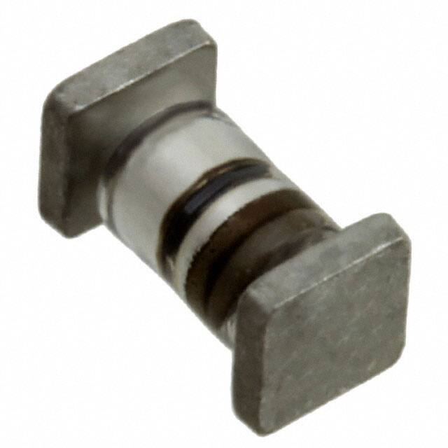
JAN1N5615US

JAN1N5615US

  • 厂商:

    ACTEL(微芯科技)

  • 封装:

    MELF

  • 描述:

    DIODE GEN PURP 200V 1A D-5A

  • 详情介绍
  • 数据手册
  • 价格&库存
JAN1N5615US 数据手册
1N5615US thru 1N5623US SURFACE MOUNT VOIDLESSHERMETICALLY SEALED FAST RECOVERY GLASS RECTIFIERS SCOTTSDALE DIVISION APPEARANCE This “fast recovery” surface mount rectifier diode series is military qualified to MILPRF-19500/429 and is ideal for high-reliability applications where a failure cannot be tolerated. These industry-recognized 1.0 Amp rated rectifiers for working peak reverse voltages from 200 to 1000 volts are hermetically sealed with voidless-glass construction using an internal “Category I” metallurgical bond. These devices are also available in axial-leaded package configurations for thru-hole mounting (see separate data sheet for 1N5615 thru 1N5623). Microsemi also offers numerous other rectifier products to meet higher and lower current ratings with various recovery time speed requirements including fast and ultrafast device types in both through-hole and surface mount packages. Package “A” or D-5A IMPORTANT: For the most current data, consult MICROSEMI’s website: http://www.microsemi.com FEATURES APPLICATIONS / BENEFITS • Surface mount package series equivalent to the JEDEC registered 1N5615 to 1N5623 series • Voidless hermetically sealed glass package • Triple-Layer Passivation • Internal “Category I” Metallurgical bonds • Working Peak Reverse Voltage 200 to 1000 Volts. • JAN, JANTX, JANTXV, and JANS available per MILPRF-19500/429 • Axial-leaded equivalents also available (see separate data sheet for 1N5615 thru 1N5623) • • • • • • • • Fast recovery 1 Amp rectifiers 200 to 1000 V Military and other high-reliability applications General rectifier applications including bridges, halfbridges, catch diodes, etc. High forward surge current capability Extremely robust construction Low thermal resistance Controlled avalanche with peak reverse power capability Inherently radiation hard as described in Microsemi MicroNote 050 MAXIMUM RATINGS • • • • • • o WWW . Microsemi .C OM DESCRIPTION MECHANICAL AND PACKAGING • o Junction & Storage Temperature: -65 C to +175 C Thermal Resistance: 13oC/W junction to end cap Thermal Impedance: 4.5oC/W @ 10 ms heating time Average Rectified Forward Current (IO): 1.0 Amps @ TA = 55ºC Forward Surge Current: 30 Amps @ 8.3 ms half-sine Solder Temperatures: 260ºC for 10 s (maximum) • • • • • CASE: Hermetically sealed voidless hard glass with Tungsten slugs TERMINATIONS: End caps are Copper with Tin/Lead (Sn/Pb) finish. Note: Previous inventory had solid Silver end caps with Tin/Lead (Sn/Pb) finish. MARKING & POLARITY: Cathode band only TAPE & REEL option: Standard per EIA-481-B WEIGHT: 193 mg See package dimensions and recommended pad layout on last page ELECTRICAL CHARACTERISTICS 1N5615US 1N5617US 1N5619US 1N5621US 1N5623US 200 400 600 800 1000 MINIMUM BREAKDOWN VOLTAGE VBR @ 50μA VOLTS 220 440 660 880 1100 AVERAGE RECTIFIED CURRENT IO @ T A (NOTE 1) AMPS o o 50 C 100 C .750 1.00 .750 1.00 .750 1.00 .750 1.00 .750 1.00 FORWAR D VOLTAGE (MAX.) VF @ 3A VOLTS REVERSE CURRENT (MAX.) IR @ VRWM o .8 MIN. 1.6 MAX. 25 C .5 .5 .5 .5 .5 μA o 100 C 25 25 25 25 25 pF MAXIMUM SURGE CURRENT IFSM (NOTE 2) AMPS REVERSE RECOVERY (MAX.) (NOTE 3) trr ns 45 35 25 20 15 25 25 25 25 25 150 150 250 300 500 CAPACITANCE (MAX.) C @ VR =12 V f=1 MHz NOTE 1: From 1 Amp at TA = 55oC, derate linearly at 5.56 mA/ oC to 0.75 Amp at TA = 100oC. From TA = 100oC, derate linearly at 7.5 mA/oC to 0 Amps at TA = 200 oC. These ambient ratings are for PC boards where thermal o resistance from mounting point to ambient is sufficiently controlled where TJ(max) does not exceed 175 C. o NOTE 2: TA = 100 C, f = 60 Hz, IO = 750 mA for ten 8.3 ms surges @ 1 minute intervals NOTE 3: IF = 0.5A, IRM = 1A, IR(REC) = 0.250 A Copyright © 2009 10-06-2009 REV E; SD47A.pdf Microsemi Scottsdale Division 8700 E. Thomas Rd. PO Box 1390, Scottsdale, AZ 85252 USA, (480) 941-6300, Fax: (480) 947-1503 Page 1 1N5615US – 1N5623US TYPE WORKING PEAK REVERSE VOLTAGE VRWM VOLTS 1N5615US thru 1N5623US SURFACE MOUNT VOIDLESSHERMETICALLY SEALED FAST RECOVERY GLASS RECTIFIERS SCOTTSDALE DIVISION Symbol VBR VRWM IO VF IR C trr Minimum Breakdown Voltage: The minimum voltage the device will exhibit at a specified current Working Peak Reverse Voltage: The maximum peak voltage that can be applied over the operating temperature range Average Rectified Output Current: Output Current averaged over a full cycle with a 50 hZ or 60 Hz sine-wave input and a 180 degree conduction angle Maximum Forward Voltage: The maximum forward voltage the device will exhibit at a specified current Maximum Leakage Current: The maximum leakage current that will flow at the specified voltage and temperature Capacitance: The capacitance in pF at a frequency of 1 MHz and specified voltage Reverse Recovery Time: The time interval between the instant the current passes through zero when changing from the forward direction to the reverse direction and a specified decay point after a peak reverse current occurs. WWW . Microsemi .C OM SYMBOLS & DEFINITIONS Definition GRAPHS FIGURE 1 TYPICAL REVERSE CURRENT vs VR FIGURE 2 TYPICAL FORWARD VOLTAGE vs FORWARD CURRENT 1N5615US – 1N5623US Copyright © 2009 10-06-2009 REV E; SD47A.pdf Microsemi Scottsdale Division 8700 E. Thomas Rd. PO Box 1390, Scottsdale, AZ 85252 USA, (480) 941-6300, Fax: (480) 947-1503 Page 2 1N5615US thru 1N5623US SURFACE MOUNT VOIDLESSHERMETICALLY SEALED FAST RECOVERY GLASS RECTIFIERS SCOTTSDALE DIVISION NOTE: This Package Outline has also previously been identified as “D-5A” WWW . Microsemi .C OM PACKAGE DIMENSIONS AND PAD LAYOUT PAD LAYOUT INCHES mm A 0.246 6.25 MIN MAX MIN MAX B 0.067 1.70 BD .097 .103 2.46 2.62 C 0.105 2.67 BL .185 .200 4.70 5.08 ECT .019 .028 0.48 0.71 S .003 --- 0.08 --- INCHES mm Note: If mounting requires adhesive separate from the solder, an additional 0.060 inch diameter contact may be placed in the center between the pads as an optional spot for cement. 1N5615US – 1N5623US Copyright © 2009 10-06-2009 REV E; SD47A.pdf Microsemi Scottsdale Division 8700 E. Thomas Rd. PO Box 1390, Scottsdale, AZ 85252 USA, (480) 941-6300, Fax: (480) 947-1503 Page 3
JAN1N5615US
物料型号:1N5615US至1N5623US

器件简介:这些二极管是军用级别的,符合MILPRF-19500/429标准,适用于高可靠性应用,工作峰值反向电压从200到1000伏。它们采用无空洞玻璃封装和内部“类别I”冶金键合。

引脚分配:文档中没有提供具体的引脚分配信息,但提到了表面安装封装与JEDEC注册的1N5615至1N5623系列等效。

参数特性: - 工作峰值反向电压:200至1000伏 - 平均整流电流:在55°C时为1.0安培,随温度变化有特定的降额曲线 - 最大正向电压:在3安培时的最大电压 - 最大反向电流:在工作峰值反向电压下的最大电流 - 电容:在1MHz频率和特定电压下的电容值 - 最大浪涌电流:在特定条件下的浪涌电流能力 - 反向恢复时间:从正向到反向电流通过零点的时间间隔

功能详解:文档提供了器件的电气特性和图形,包括典型反向电流与反向电压的关系,以及典型正向电压与正向电流的关系。

应用信息:适用于军事和其他高可靠性应用,包括整流桥、半桥、捕获二极管等一般整流应用。

封装信息:提供了封装尺寸和推荐的焊盘布局,注意此封装也曾被称为“D-5A”。
JAN1N5615US 价格&库存

很抱歉,暂时无法提供与“JAN1N5615US”相匹配的价格&库存,您可以联系我们找货

免费人工找货