MIC2920X
400 mA Low Dropout Regulators
Features
General Description
•
•
•
•
•
•
•
•
The MIC2920 family (MIC2920A, MIC29201,
MIC29202, and MIC29204) are efficient voltage
regulators with very low dropout voltage (typically
40 mV at light loads and 370 mV at 250 mA) and very
low quiescent current (140 μA typical). The quiescent
current of the MIC2920A increases only slightly in
dropout, prolonging battery life. Key MIC2920A
features include protection against reversed battery,
fold-back current limiting, and automotive “load dump”
protection (60V positive transient).
•
•
•
•
High Output Voltage Accuracy
Ensured 400 mA Output
Low Quiescent Current
Low Dropout Voltage
Extremely Tight Load and Line Regulation
Very Low Temperature Coefficient
Current and Thermal Limiting
Input Withstands –20V Reverse Battery and +60V
Positive Transients
Error Flag Warns of Output Dropout
Logic-Controlled Electronic Shutdown
Output Programmable from 1.24V to 26V
(MIC29202/MIC29204)
Available in TO-220-3, TO-220-5, and
Surface-Mount TO-263-5, SOT-223, and SOIC-8
Packages
Applications
•
•
•
•
•
•
•
•
•
Battery-Powered Equipment
Cellular Telephones
Laptop, Notebook, and Palmtop Computers
PCMCIA VCC and VPP Regulation/Switching
Barcode Scanners
Automotive Electronics
SMPS Post-Regulators
Voltage Reference
High-Efficiency Linear Power Supplies
2021 Microchip Technology Inc. and its subsidiaries
The MIC2920 family of devices are available in several
configurations. The MIC2920A-x.x devices are 3-lead
fixed-voltage regulators available in 3.3V, 4.85V, 5V,
and 12V outputs. The MIC29201 is a fixed-voltage
regulator that offers a logic-compatible ON/OFF
(shutdown) input and an error flag output. This flag may
also be used as a power-on reset signal. A
logic-compatible shutdown input is provided on the
adjustable MIC29202, which allows the regulator to be
switched on and off. The MIC29204 8-lead SOIC
adjustable regulator includes both shutdown and error
flag pins and may be pin-strapped for 5V output or
programmed from 1.24V to 26V using two external
resistors.
DS20006601A-page 1
�MIC2920X
Package Types
MIC2920A (FIXED)
3-Lead SOT-223 (S)
MIC29201 (FIXED)
8-Lead SOIC (M)
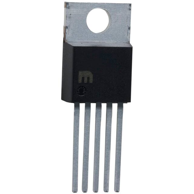
MIC2920A (FIXED)
3-Lead TO-220 (T)
TAB
8 INPUT
OUTPUT 1
TAB
SENSE 2
7 NC
SHUTDOWN 3
6 NC
5 ERROR
GROUND 4
1
2
3
INPUT
OUTPUT
GROUND
MIC29201/MIC29202 (ADJ.)
5-Lead TO-220 (T)
MIC29201/MIC29202 (ADJ.)
5-Lead TO-263 (U)
TAB
TAB
1
IN
3
OU T
GND
2
MIC29204 (ADJ.)
8-Lead SOIC/8-Lead PDIP (M/N)
OUTPUT 1
SENSE 2
1 2 3 4 5
DS20006601A-page 2
8 INPUT
1 2 3 4 5
5-Lead Package Pinouts:
7 A D JUST
SHUTDOWN 3
6 5V TAP
Pin #
MIC29201
MIC29202
GROUND 4
5 ERROR
1
Error
Adjust
2
Input
Shutdown
3
Ground
Ground
4
Output
Input
5
Shutdown
Output
2021 Microchip Technology Inc. and its subsidiaries
�MIC2920X
Typical Application Circuits
MIC2920A-5.0 FIXED 5V REGULATOR
MIC29202/4 ADJUSTABLE REGULATOR (PINOUT FOR MIC29204)
V IN
+V IN
100kΩ
8
VIN
+V IN
V OUT = 5V
V OUT
+ 10μF
V OUT
5 ERROR
ERROR
OUTPUT
3
SHUTDOWN
INPUT
SHUTDOWN
10μF
R 1 100
pF
OFF
GND
GND ADJU ST
7
4
1.23V
ON
MIC29202/4 5V OR 3.3V SELECTABLE REGULATOR WITH
SHUTDOWN (PINOUT FOR MIC29204)
R1
V OUT = V R E F x (1 +
)
R2
MIC29204 WIDE INPUT VOLTAGE RANGE CURRENT LIMITER
8
+V IN
3
HIGH = OFF
V CC OUT
VOUT
+V IN
1
SHUTDOWN
8
+VIN
+
HIGH = 5V OUT
ADJUST
7
220kΩ
1%
470 kΩ
10μF
300kΩ
1%
100pF
LOW = ON
GND
4
R2
VREF
NOTE: PINS 2 AND 6 ARE LEFT OPEN
≥ 5.3V
SHUTDOWN
INPUT
26V
1.2
VOUT 1
SHUTDOWN
INPUT
180kΩ
1%
3
SD
OFF
2N2222
LOW = 3.3V OUT
*V OUT = V IN
VOUT 1
5 ERROR
ERROR
OUTPUT
GND ADJ U ST
4
7
ON
PIN 3 LOW= ENABLE OUTPUT. Q1 ON = 3.3V, Q1 OFF = 5.0V.
* Minimum Input-Output Voltage ranges from 40mV to 400mV, depending on load current
Schematic Diagram
ADJUST
IN
R18
20k Ω
Q15A
Q15B
Q24
Q26
Q25
OUT
Q9
Q3
R11
18
kΩ
Q7
Q4
Q6
SENSE
Q8
Q5
C1
20
pF
R11
20.6
kΩ
Q14
Q17
Q16
R27
R17
12 kΩ
V TAP
Q1
Q20
R1
20 k Ω
Q42
R28
Q2
10
R2
50 kΩ
R6
140
kΩ
R5
180
kΩ
Q40
Q13
Q22
R10
150
kΩ
R8
31.4 k Ω
Q21
Q23
C2
40 pF
R9
27.8 kΩ
R12
110
kΩ
Q12
R15
100 kΩ
R14
350
kΩ
R13
100
kΩ
R16
30 k Ω
Q11
Q41
R17
10 Ω
Q29
R30
30
kΩ
Q19
Q18
Q28
R3
50 kΩ
R4
13 kΩ
R21 8 Ω
50 kΩ
Q30 Q31
Q37
10 kΩ
R22
150 kΩ
Q36
R24
50 k Ω
R23 60 k Ω
SHDN
ERROR
Q34
Q38
R26
60 k Ω
Q39
2021 Microchip Technology Inc. and its subsidiaries
D E NO T E S CO NNE CT I O N O N
MIC2920A-xx AND MIC29201-xx
VERSIONS ONLY
R25
2.8 k Ω
GND
DS20006601A-page 3
�MIC2920X
1.0
ELECTRICAL CHARACTERISTICS
Absolute Maximum Ratings †
Input Supply Voltage ................................................................................................................................... –20V to +60V
Adjust Input Voltage (Note 1, Note 2)......................................................................................................... –1.5V to +26V
Power Dissipation (Note 3).....................................................................................................................Internally Limited
Operating Ratings ‡
Operating Input Supply Voltage (Note 4)....................................................................................................... +2V to +26V
Adjust Input Voltage (Note 1, Note 2)......................................................................................................... –1.5V to +26V
Shutdown Input Voltage ............................................................................................................................. –0.3V to +30V
Error Comparator Output Voltage............................................................................................................... –0.3V to +30V
† Notice: Stresses above those listed under “Absolute Maximum Ratings” may cause permanent damage to the device.
This is a stress rating only and functional operation of the device at those or any other conditions above those indicated
in the operational sections of this specification is not intended. Exposure to maximum rating conditions for extended
periods may affect device reliability.
‡ Notice: The device is not guaranteed to function outside its operating ratings.
Note 1: Comparator thresholds are expressed in terms of a voltage differential at the Adjust terminal below the nominal reference voltage measured at 6V input. To express these thresholds in terms of output voltage change,
multiply by the error amplifier gain = VOUT/VREF = (R1 + R2)/R2. For example, at a programmed output voltage of 5V, the Error output is ensured to go low when the output drops by 95 mV x 5V/1.235V = 384 mV.
Thresholds remain constant as a percent of VOUT as VOUT is varied, with the dropout warning occurring at
typically 5% below nominal, 7.7% ensured.
2: VSHUTDOWN ≥ 2V, VIN ≤ 26V, VOUT = 0, with the Adjust pin tied to 5V Tap or to the R1, R2 junction (see the
MIC29202/29204 Adjustable Regulator in Typical Application Circuits) with R1 ≥ 150 kΩ.
3: The maximum allowable power dissipation is a function of the maximum junction temperature, TJ(MAX), the
junction-to-ambient thermal resistance, θJA, and the ambient temperature, TA. The maximum allowable
power dissipation at any ambient temperature is calculated using: P(MAX) = (TJ(MAX) – TA) ÷ θJA. Exceeding
the maximum allowable power dissipation will result in excessive die temperature, and the regulator will go
into thermal shutdown.
4: Across the full operating temperature, the minimum input voltage range for full output current is 4.3V to 26V.
Output will remain in-regulation at lower output voltages and low current loads down to an input of 2V at
25°C.
DS20006601A-page 4
2021 Microchip Technology Inc. and its subsidiaries
�MIC2920X
ELECTRICAL CHARACTERISTICS
Electrical Characteristics: Limits in standard typeface are for TJ = +25°C and limits in boldface apply over the full
operating temperature range. Unless otherwise specified, VIN = VOUT + 1V, IL = 1 mA, CL = 10 μF. Adjustable
versions are set for an output of 5V. The MIC29202 VSHUTDOWN ≤ 0.7V. The 8-lead MIC29204 is configured with the
Adjust pin tied to the 5V Tap, the Output is tied to Output Sense (VOUT = 5V), and VSHUTDOWN ≤ 0.7V. (Note 1)
Parameter
Output Voltage Accuracy
Output Voltage
Temperature Coefficient
Symbol
VO
ΔVO/ΔT
Line Regulation
ΔVO/VO
Load Regulation
ΔVO/VO
Dropout Voltage (Note 4)
Ground Pin Current
(Note 5)
Ground Pin Current at
Dropout (Note 5)
Current Limit
Thermal Regulation
Output Noise Voltage
(10 Hz to 100 kHz),
IL = 100 mA
VIN – VO
IGND
IGNDDO
ILIMIT
ΔVO/ΔPD
en
Min.
Typ.
Max.
–1
—
1
–2
—
2
–2.5
—
2.5
–1.5
—
1.5
–3
—
3
–4
—
4
—
20
100
—
80
350
—
0.03
0.10
—
—
0.40
—
0.04
0.16
—
—
0.30
—
100
150
—
—
180
—
250
—
—
350
—
—
370
—
—
500
—
—
400
600
—
—
750
—
140
200
—
—
300
—
1.3
2
—
—
2.5
—
5
9
—
—
12
—
13
15
—
180
400
—
425
100
—
—
1200
—
0.05
0.2
—
400
—
—
260
—
2021 Microchip Technology Inc. and its subsidiaries
Units
Conditions
Variation from factory trimmed VOUT
%
1 mA ≤ IL ≤ 400 mA, across temp range
MIC2920A-12 and MIC29201-12 only
1 mA ≤ IL ≤ 400 mA, across temp range
ppm/°C
Note 2
VOUT > 10V only
%
VIN = VOUT + 1V to 26V
%
IL = 1 mA to 250 mA (Note 3)
IL = 1 mA
IL = 100 mA
mV
VOUT > 10V only
IL = 250 mA
VOUT > 10V only
IL = 400 mA
µA
IL = 1 mA
IL = 100 mA
mA
IL = 250 mA
IL = 400 mA
µA
mA
%/W
µVRMS
VIN = 0.5V less than designed VOUT,
(VOUT = 3.3V), IO = 1 mA
VOUT = 0V
Note 6
Note 7
CL = 10 µF
CL = 100 µF
DS20006601A-page 5
�MIC2920X
ELECTRICAL CHARACTERISTICS (CONTINUED)
Electrical Characteristics: Limits in standard typeface are for TJ = +25°C and limits in boldface apply over the full
operating temperature range. Unless otherwise specified, VIN = VOUT + 1V, IL = 1 mA, CL = 10 μF. Adjustable
versions are set for an output of 5V. The MIC29202 VSHUTDOWN ≤ 0.7V. The 8-lead MIC29204 is configured with the
Adjust pin tied to the 5V Tap, the Output is tied to Output Sense (VOUT = 5V), and VSHUTDOWN ≤ 0.7V. (Note 1)
Parameter
Symbol
Min.
Typ.
Max.
1.223
1.235
1.247
1.210
—
1.260
1.204
—
1.266
1.210
1.235
1.260
1.200
—
1.270
1.185
—
1.285
—
20
40
—
—
60
Units
Conditions
MIC29202, MIC29204
Reference Voltage
VREF
Reference Voltage
VREF
V
MIC29202
V
MIC29202, Note 8
V
MIC29204
V
MIC29204, Note 8
nA
—
Reference Voltage
VREF
Reference Voltage
VREF
Adjust Pin Bias Current
IBIAS
Reference Voltage
Temperature Coefficient
ΔVREF/ΔT
—
20
—
ppm/°C
Adjust Pin Bias Current
Temperature Coefficient
ΔIBIAS/ΔT
—
0.1
—
nA/°C
Note 7
—
Error Comparator MIC29201, MIC29204
Output Leakage Current
—
Output Low Voltage
VOL
Upper Threshold Voltage
VUTH
Lower Threshold Voltage
VLTH
Hysteresis
HYS
DS20006601A-page 6
—
0.01
1.00
—
—
2.00
—
150
250
—
—
400
40
60
—
25
—
—
—
75
95
—
—
140
—
15
—
µA
VOH = 26V
mV
VIN = 4.5V, IOL = 250 µA
mV
Note 9
mV
Note 9
mV
Note 9
2021 Microchip Technology Inc. and its subsidiaries
�MIC2920X
ELECTRICAL CHARACTERISTICS (CONTINUED)
Electrical Characteristics: Limits in standard typeface are for TJ = +25°C and limits in boldface apply over the full
operating temperature range. Unless otherwise specified, VIN = VOUT + 1V, IL = 1 mA, CL = 10 μF. Adjustable
versions are set for an output of 5V. The MIC29202 VSHUTDOWN ≤ 0.7V. The 8-lead MIC29204 is configured with the
Adjust pin tied to the 5V Tap, the Output is tied to Output Sense (VOUT = 5V), and VSHUTDOWN ≤ 0.7V. (Note 1)
Parameter
Symbol
Min.
Typ.
Max.
Units
Conditions
Shutdown Input MIC29201, MIC29202, MIC29204
Input Logic Voltage
Shutdown Pin Input
Current
Regulator Output Current
in Shutdown
—
IIN(SHDN)
—
—
1.3
—
—
—
0.7
2.0
—
—
—
30
50
—
—
100
—
450
600
—
—
750
—
3
10
—
—
20
—
V
Low (ON)
High (OFF)
VSHUTDOWN = 2.4V
µA
VSHUTDOWN = 26V
µA
Note 10
Note 1:
2:
Devices are ESD protected. However, handling precautions are recommended.
Output voltage temperature coefficient is defined as the worst case voltage change divided by the total
temperature range.
3: Regulation is measured at constant junction temperature using low duty cycle pulse testing. Changes in
output voltage due to heating effects are covered by the thermal regulation specification.
4: Dropout Voltage is defined as the input to output differential at which the output voltage drops 100 mV
below its nominal value measured at 1V differential. At low values of programmed output voltage, the minimum input supply voltage of 4.3V over temperature must be taken into account. The MIC2920A operates
down to 2V of input at reduced output current at 25°C.
5: Ground pin current is the regulator quiescent current. The total current drawn from the supply is the sum of
the load current plus the ground pin current.
6: The MIC2920A features fold-back current limiting. The short circuit (VOUT = 0V) current limit is less than
the maximum current with normal output voltage.
7: Thermal regulation is defined as the change in output voltage at a time “t” after a change in power dissipation is applied, excluding load or line regulation effects. Specifications are for a 200 mA load pulse at VIN =
20V (a 4W pulse) for t = 10 ms.
8: VREF ≤ VOUT ≤ (VIN – 1V), 4.3V ≤ VIN ≤ 26V, 1 mA < IL ≤ 400 mA, TJ ≤ TJ(MAX).
9: Comparator thresholds are expressed in terms of a voltage differential at the Adjust terminal below the
nominal reference voltage measured at 6V input. To express these thresholds in terms of output voltage
change, multiply by the error amplifier gain = VOUT/VREF = (R1 + R2)/R2. For example, at a programmed
output voltage of 5V, the Error output is guaranteed to go low when the output drops by 95 mV x
5V/1.235V = 384 mV. Thresholds remain constant as a percent of VOUT as VOUT is varied, with the dropout warning occurring at typically 5% below nominal, 7.7% ensured.
10: VSHUTDOWN ≥ 2V, VIN ≤ 26V, VOUT = 0, with the Adjust pin tied to 5V Tap or to the R1, R2 junction (see the
MIC29202/29204 Adjustable Regulator in Typical Application Circuits) with R1 ≥ 150 kΩ.
11: When used in dual supply systems where the regulator load is returned to a negative supply, the output
voltage must be diode clamped to ground.
12: Maximum positive supply voltage of 60V must be of limited duration (


 工商网监
湘ICP备2023018690号
工商网监
湘ICP备2023018690号
