PL485 Datasheet
Scope
This document is an overview of the main features of the PL485 microprocessor. The sole reference documents for
product information on the PL485 are listed in Reference Documents.
Introduction
The PL485 is a fully programmable Power Line Communication (PLC) System On Chip (SOC). It is able to run any
narrowband-PLC (NB-PLC) protocol in the frequency band up to 500 kHz. By means of selecting the proper firmware,
the PL485 is able to support applications requiring basic connectivity (point to point, star) or complex PLC networks
(mesh topologies with routing).
Microchip provides firmware examples for basic PLC connectivity, as well as implementations of state-of-the-art PLC
®
®
protocols such as ITU-T G.9903 (G3-PLC ) and ITU-T G.9904 (PRIME ). The PL485 is a future-proof modem able to
support the evolution of the implemented NB-PLC standards.
Reference Documents
Type
Document Title
Available
Ref. No.
Data sheet
PL360 Datasheet
www.microchip.com
70005364
Data sheet
SAM G55J Datasheet
www.microchip.com
11289
© 2020 Microchip Technology Inc.
Datasheet
60001600B-page 1
�Table of Contents
Scope............................................................................................................................................................. 1
Introduction.....................................................................................................................................................1
Reference Documents....................................................................................................................................1
1.
Features.................................................................................................................................................. 3
2.
Applications.............................................................................................................................................5
3.
Block Diagram.........................................................................................................................................6
4.
Chip Identifier.......................................................................................................................................... 7
5.
Package and Ballout............................................................................................................................... 8
5.1.
5.2.
5.3.
6.
Electrical Characteristics....................................................................................................................... 11
6.1.
6.2.
6.3.
6.4.
7.
Packages......................................................................................................................................8
Ballout.......................................................................................................................................... 8
Recommended SAMG55-PL360 Connection.............................................................................10
Decoupling..................................................................................................................................11
Power Sequences...................................................................................................................... 11
Thermal Characteristics..............................................................................................................11
Power Consumption................................................................................................................... 11
Mechanical Characteristics................................................................................................................... 12
7.1.
121-Ball TFBGA......................................................................................................................... 12
8.
Recommended Mounting Conditions.................................................................................................... 16
9.
Marking................................................................................................................................................. 17
10. Ordering Information............................................................................................................................. 18
11. Revision History.................................................................................................................................... 19
11.1. Rev A - 12/2019......................................................................................................................... 19
11.2. Rev B - 03/2020......................................................................................................................... 19
The Microchip Website.................................................................................................................................20
Product Change Notification Service............................................................................................................20
Customer Support........................................................................................................................................ 20
Microchip Devices Code Protection Feature................................................................................................ 20
Legal Notice................................................................................................................................................. 20
Trademarks.................................................................................................................................................. 21
Quality Management System....................................................................................................................... 21
Worldwide Sales and Service.......................................................................................................................22
© 2020 Microchip Technology Inc.
Datasheet
60001600B-page 2
�Features
1.
Features
•
•
•
•
•
•
•
Programmable Narrow-Band Power Line Communication (NB-PLC) system on chip
Complies with FCC, CENELEC, ARIB and K.60 regulations
Embedded NB-PLC modem:
– PLC front-end integrated, including PGA and digital transmission level control
– High performance, programmable engine dedicated to PLC PHY and MAC real-time tasks with dedicated
SRAM memory
– Cryptographic engine supporting AES 128, 192, 256
– Modem secure boot implemented, comprising PLC binary authentication (AES-128 CMAC) and decryption
(AES-128 CBC)
®
®
Fully programmable, standard ARM 32-bit Cortex -M4 core running the upper protocol layers and user
application:
– ARM Cortex-M4 with up to 16 Kbytes SRAM on I/D bus providing 0 wait state execution at up to 100 MHz(1)
– Memory Protection Unit (MPU)
– DSP Instructions
– Floating Point Unit (FPU)
®
– Thumb -2 instruction set
Memories:
– Up to 512 Kbytes embedded Flash
– Up to 176 Kbytes embedded SRAM
– 8 Kbytes ROM with embedded boot loader, single-cycle access at full speed
System:
– Embedded voltage regulator for single-supply operation
– Power-on reset (POR) and Watchdog for safe operation
– Quartz or ceramic resonator oscillators: 3 to 20 MHz with clock failure detection and 32.768 kHz for RTT or
system clock
– High-precision 8/16/24 MHz factory-trimmed internal RC oscillator. In-application trimming access for
frequency adjustment
– Slow clock internal RC oscillator as permanent low-power mode device clock
– PLL range from 48 MHz to 100 MHz for device clock
– PLL range from 24 MHz to 48 MHz for USB device and USB OHCI
– Up to 30 peripheral DMA (PDC) channels
– 256-bit General-Purpose Backup Registers (GPBR)
– 15 external interrupt lines
Peripherals(2):
– 8 flexible communication units supporting:
• USART
• SPI
• Two-wire Interface (TWI) featuring TWI masters and high-speed TWI slaves
– Crystal-less USB 2.0 Device and USB Host OHCI with On-chip Transceiver
– 2 Inter-IC Sound Controllers (I2S)
– 1 Pulse Density Modulation Interface (PDMIC) (supports up to two microphones)
– 2 three-channel 16-bit Timer/Counters (TC) with capture, waveform, compare and PWM modes
– 1 48-bit Real-Time Timer (RTT) with 16-bit prescaler and 32-bit counter
– 1 RTC with calendar and alarm features
– 1 32-bit Cyclic Redundancy Check Calculation Unit (CRCCU)
© 2020 Microchip Technology Inc.
Datasheet
60001600B-page 3
�Features
•
•
•
•
I/O(2):
– Up to 48 I/O lines with external interrupt capability (edge or level), debouncing, glitch filtering and on-die
series resistor termination. Individually programmable open-drain, pull-up and pull-down resistor and
synchronous output
– Two PIO Controllers provide control of up to 48 I/O lines
Analog:
– One 8-channel ADC, resolution up to 12 bits, sampling rate up to 500 ksps
Package: available in TFBGA-121
Temperature Range: Industrial (-40ºC to +85ºC)
Note:
1. 100 MHz with VDDCOREXT100 or with VDDCORE trimmed by regulator.
2. Communication between SAMG55 and PL360 blocks requires some peripherals and GPIOs which will not be
available for other uses. Please, refer to section 5.3 Recommended SAMG55-PL360 Connection for more
information about connection between SAMG55 and PL360 blocks.
© 2020 Microchip Technology Inc.
Datasheet
60001600B-page 4
�Applications
2.
Applications
•
•
IoT and Industrial: Smart Lighting, Fire and alarm systems, Solar, Home Automation
Internet of Energy: Advanced Metering Infrastructure, Smart Grid, Home/Building Energy Management Systems
(HEMS/BEMS), Heating, Ventilation and Air Conditioning (HVAC)
© 2020 Microchip Technology Inc.
Datasheet
60001600B-page 5
�Block Diagram
Block Diagram
Power
Management
Controller
IO
JTAG and Serial Wire
RC OSC
8/16/24 MHz
In-Circuit Emulator
Cortex-M4 Processor
fMAX 100 MHz
Backup area
Supply
Controller
WKUP[15:0]
DSP
XIN32
XOUT32
XIN
XOUT
MPU
32K OSC
S
Power-on
Reset
256-bit
General-purpose
Backup Registers
Real-time
Clock
Real-time
Timer
M
Supply
Monitor
Flash
Unique
Identifier
D
CMCC
2/4/8 Kb Cache
Reset
Controller
Watchdog
Timer
FPU
I
32K RC
NRST
24-bit SysTick
Counter
NVIC
Tamper Detection
SRAM
User
Signature
16 Kbytes
Flash
M
S
512 Kbytes
4-layer AHB Bus Matrix
fMAX 100 MHz
S
160 Kbytes
S
M
M
SRAM
ROM
M S
8 Kbytes
PIOA/PIOB
CRCCU
AHB/APB
Bridge
PDC
DMA
USB OHCI
MUX
System Controller
PDC
AD[7:0]
ADTRG
2668
bytes
FIFO
12-bit ADC
PDMIC_DAT
PDMIC_CLK
PDMIC0
PDMIC1
I2SCK0...1
I2SWS0...1
I2SDI0...1
I2SDO0...1
I2SMCK0...1
PDC
PDC
USB 2.0
Full-speed
Timer Counter A
2 x I2SC
TCLK[2:0]
TIOA[2:0]
TIOB[2:0]
TC[0..2]
FLEXCOM
SCK_SPCK0...7
TXD_MOSI_TWD0...7
RXD_MISO_TWCK0...7
RTS_NPCS1_0...7
CTS_NPCS0NSS_0...7
DP
DM
Event System
PDC
Transceiver
PLLUSB
ERASE
VDDCORE
D
O
Voltage
Regulator
PLLA
VDDIO
VD
VD
D
TST
PCK[2:0]
VDDUSB
U
T
TD
I
TD
O
TM
S
TC /SW
K/ D
SW IO
JT
C
LK
AG
SE
L
Figure 3-1. PL485 Block Diagram
Timer Counter B
PDC
TC[3..5]
8x
USART, SPI, TWI
SAMG55
SPI
&
Control Signals
PL_EMIT[3:0]
PL_TXRX[1:0]
PL_AGC
PL_VIN
PL360
PL_VCZ
PL
PL _VR
_ E
PL VR FP
_V EF
R C
EF
N
P
PL L_X
_X IN
O
U
T
PL AB
_N LE
R
ST
N
SW
C
TR S LK
AC WD
ES IO
W
O
_L
D
O
_E
PL
_P
Ax
PL485
PL
3.
© 2020 Microchip Technology Inc.
Datasheet
60001600B-page 6
�Chip Identifier
4.
Chip Identifier
Table 4-1. Chip ID Registers
Chip Name
CHIPID_CIDR
CHIPID_EXID
SAM G55J19
0x2457_0AE1
0x0
© 2020 Microchip Technology Inc.
Datasheet
60001600B-page 7
�Package and Ballout
5.
Package and Ballout
5.1
Packages
The PL485 is available in the packages listed in the following table:
Table 5-1. PL485 Packages
5.2
Package Name
Ball Count
Ball Pitch
Package Size
TFBGA121
121
0.80 mm
10 x 10 mm2
Ballout
Table 5-2. PL485 Ballout
A1
GND
C3
GND
E5
PL_PA0
G7
PA30
J9
PA14
A2
PL_VZC
C4
GND
E6
PL_PA3
G8
PB10
J10
PA13
A3
PL_PA1
C5
GND
E7
PL_PA8/MOSI
G9
PA9
J11
PA12
A4
VDDIO
C6
AGND
E8
PL_PA9/MISO
G10
PB5
K1
PA1
A5
VDDIN_AN
C7
GND
E9
VDDIO
G11
PB8/XOUT
K2
PA5
A6
PL_VREFC
C8
GND
E10
VDDIO
H1
PA0
K3
PA8
A7
PL_VIN
C9
GND
E11
VDDIO
H2
PA2
K4
PA16
A8
AGND
C10
PL_EMIT3
F1
PA31
H3
MCU_NRST
K5
VDDIO
A9
PL_TXRX0
C11
PL_EMIT2
F2
PB15
H4
MCU_TST
K6
PA22
A10
PL_TXRX1
D1
PL_VDDCORE
F3
PA25
H5
VDDIO
K7
ADVREF
A11
GND
D2
PL_PA4/SWDIO
F4
PB13
H6
GND
K8
PA18
B1
PL_XOUT
D3
PL_PA2/TRACESWO
F5
PA24
H7
GND
K9
PA20
B2
PL_XIN
D4
PL_NRST
F6
PA26
H8
PA19
K10
PB0
B3
GND
D5
GND
F7
PA28
H9
PB11
K11
PB3
B4
VDDIO
D6
GND
F8
PA27
H10
PA11
L1
GND
B5
AGND
D7
GND
F9
PB7
H11
PA10
L2
MCU_VDDCORE
B6
PL_VREFN
D8
GND
F10
PB6
J1
PA4
L3
PA6
B7
PL_VREFP
D9
VDDIO
F11
PB9/XIN
J2
PA3
L4
PA15
B8
VDDIN_AN
D10
PL_EMIT1
G1
PB14
J3
PA7
L5
PA23
B9
PL_AGC
D11
PL_EMIT0
G2
PB4
J4
PB12
L6
PA21
B10
VDDIO
E1
VDDIN
G3
JTAGSEL
J5
VDDIO
L7
VDDOUT
B11
PL_VDDCORE
E2
PL_PA5/SWCLK
G4
PL_PA7/SPCK
J6
GND
L8
PB1
C1
VDDPLL
E3
PL_TST
G5
PA29
J7
VDDUSB
L9
PB2
C2
VDDPLL
E4
PL_LDO_ENABLE
G6
PL_PA6/NPCS0
J8
PA17
L10
MCU_VDDCORE
L11
GND
© 2020 Microchip Technology Inc.
Datasheet
60001600B-page 8
�Package and Ballout
Figure 5-1. PL485 Ballout
1
A
B
C
D
E
F
G
H
J
K
L
2 3 4 5
6 7 8 9 10 11
GND
PL_VZC
PL_PA1
VDDIO
VDDIN_
AN
PL_
VREFC
PL_VIN
AGND
PL_
TXRX0
PL_
TXRX1
GND
PL_XOUT
PL_XIN
GND
VDDIO
AGND
PL_
VREFN
PL_
VREFP
VDDIN_
AN
PL_AGC
VDDIO
PL_VDD
CORE
VDDPLL
VDDPLL
GND
GND
GND
AGND
GND
GND
GND
PL_VDD
CORE
PL_PA4/
SWDIO
PL_NRST
GND
GND
GND
GND
VDDIO
VDDIN
PL_PA5/
SWCLK
PL_TST
PL_LDO_
ENABLE
PL_PA0
PL_PA3
PL_PA8/
MOSI
PL_PA9/
MISO
PA31
PB15
PA25
PB13
PA24
PA26
PA28
PB14
PB4
JTAGSEL
PL_PA7/
SPCK
PA29
PL_PA6/
NPCS0
PA0
PA2
MCU_
NRST
MCU_
VDDIO
PA4
PA3
PA7
PB12
PA1
PA5
PA8
GND
MCU_VD
DCORE
PA6
Power
© 2020 Microchip Technology Inc.
PL_PA2/
TRACESWO
PL_
EMIT3
PL_
PL_
EMIT2
EMIT1
PL_
EMIT0
VDDIO
VDDIO
VDDIO
PA27
PB7
PB6
PB9/
XIN
PA30
PB10
PA9
PB5
PB8/
XOUT
GND
GND
PA19
PB11
PA11
PA10
VDDIO
GND
VDDUSB
PA17
PA14
PA13
PA12
PA16
VDDIO
PA22
ADVREF
PA18
PA20
PB0
PB3
PA15
PA23
PA21
VDDOUT
PB1
PB2
MCU_VD
DCORE
GND
TST
Ground
PL360
Datasheet
SAMG55 (MCU)
60001600B-page 9
�Package and Ballout
5.3
Recommended SAMG55-PL360 Connection
The recommended connection in the PCB between balls of the PL485 to connect SAMG55 and PL360 internal blocks
is:
Figure 5-2. Recommended SAMG55-PL360 PCB Connection
PL485 Ballout
PL360 Signal
SAMG55 Signal
PL485 Ballout
D4
PL_NRST
PA25
F3
E3
PL_TST
PB15
F2
E4
PL_LDO_ENABLE
PB13
F4
E5
PL_PA0
PA24
F5
E6
PL_PA3
PA26
F6
E7
PL_PA8/MOSI
PA28
F7
E8
PL_PA9/MISO
PA27
F8
G4
PL_PA7/SPCK
PA29
G5
G6
PL_PA6/NPCS0
PA30
G7
This connection is configured by default in Microchip Powerline communication stacks. It is highly recommended to
keep it as specified by this datasheet to guarantee proper operation of the PLC modem.
© 2020 Microchip Technology Inc.
Datasheet
60001600B-page 10
�Electrical Characteristics
6.
Electrical Characteristics
Please refer to PL360 and SAM G55J Datasheets for specific information about Electrical Characteristics.
6.1
Decoupling
For correct PLC transmission, a 4.7 µF decoupling capacitor must be added to each of the following VDDIO balls: D9,
E9, E10 and E11.
Please refer to the reference datasheets for other Decoupling Requirements.
6.2
Power Sequences
Please refer to the reference datasheets for Power Sequences Considerations.
6.3
Thermal Characteristics
Table 6-1. Thermal Resistance Data
Symbol
θJA
ΨJC
Parameter
Junction-to-ambient thermal resistance
Junction-to-top center of package thermal characterization
Condition
Typ
Still Air
31.1
1m/s
21.9
2m/s
19.6
-
1.9
Unit
ºC/W
θJA is calculated based on a standard JEDEC JESD51-5 defined environment (1.6mm thickness PCB, 4 copper
layers, 76.2mm x 114.3mm board) and is not reliable indicator of a device’s thermal performance in a non-JEDEC
environment. The customer should always perform their own calculations/simulations to ensure that their system’s
thermal performance is sufficient.
6.4
Power Consumption
Please refer to the reference datasheets for Power Consumption.
© 2020 Microchip Technology Inc.
Datasheet
60001600B-page 11
�Mechanical Characteristics
7.
Mechanical Characteristics
7.1
121-Ball TFBGA
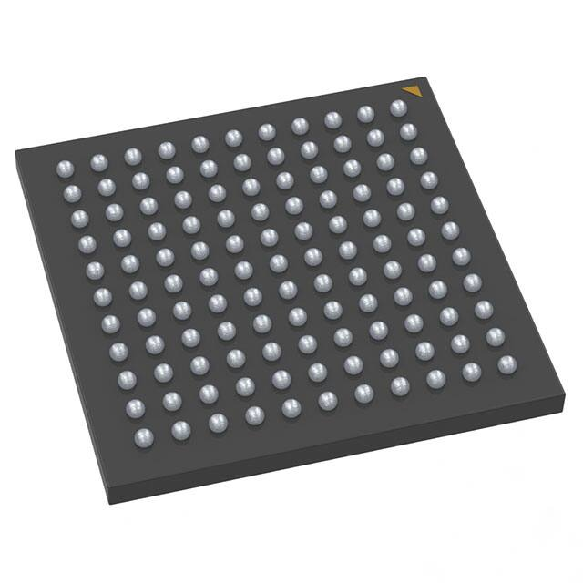
121-Ball Thin, Fine Pitch Ball Grid Array (AJA) - 10x10 mm Body [TFBGA]
Note:
For the most current package drawings, please see the Microchip Packaging Specification located at
http://www.microchip.com/packaging
A1
121X
0.12 C
D
1
NOTE 1
2
3
4
5
6
A
7
8
0.20 C
B
9 10 11
A
B
C
D
E
F
E
G
(DATUM B)
H
(DATUM A)
J
K
2X
L
0.15 C
2X
TOP VIEW
0.15 C
(S)
(M)
A
C
1
2
3
4
5
6
7
8
SEATING
PLANE
SIDE VIEW
9 10 11
L
K
J
H
e
G
F
E
D
C
B
A
NOTE 1
e
BOTTOM VIEW
121X Øb
0.15
0.08
C A B
C
Microchip Technology Drawing C04-1216A Sheet 1 of 2
© 2020 Microchip Technology Inc.
Datasheet
60001600B-page 12
�Mechanical Characteristics
121-Ball Thin, Fine Pitch Ball Grid Array (AJA) - 10x10 mm Body [TFBGA]
Note:
For the most current package drawings, please see the Microchip Packaging Specification located at
http://www.microchip.com/packaging
Units
Dimension Limits
Number of Terminals
N
e
Pitch
Overall Height
A
Terminal (ball) height
A1
Substrate Thickness
S
Mold Cap Thickness
M
Overall Length
D
Overall Width
E
b
Terminal Width
MILLIMETERS
NOM
121
0.80 BSC
0.270
0.26 REF
0.53 REF
10.00 BSC
10.00 BSC
0.38
0.40
MIN
MAX
1.20
0.37
0.48
Notes:
1. Terminal A1 visual index feature may vary, but must be located within the hatched area.
2. Dimensioning and tolerancing per ASME Y14.5M
BSC: Basic Dimension. Theoretically exact value shown without tolerances.
REF: Reference Dimension, usually without tolerance, for information purposes only.
Microchip Technology Drawing C04-1216A Sheet 2 of 2
© 2020 Microchip Technology Inc.
Datasheet
60001600B-page 13
�Mechanical Characteristics
121-Ball Thin, Fine Pitch Ball Grid Array (AJA) - 10x10 mm Body [TFBGA]
Note:
For the most current package drawings, please see the Microchip Packaging Specification located at
http://www.microchip.com/packaging
C1
1
2
3
4
5
6
7
8
9
10
11
A
E
B
C
D
E
C2
F
G
H
J
K
L
SILK SCREEN
ØX
E
RECOMMENDED LAND PATTERN
Units
Dimension Limits
E
Contact Pitch
Contact Pad Spacing
C1
Contact Pad Spacing
C2
Contact Pad Diameter (X121)
X
MIN
MILLIMETERS
NOM
0.80 BSC
8.00
8.00
MAX
0.40
Notes:
1. Dimensioning and tolerancing per ASME Y14.5M
BSC: Basic Dimension. Theoretically exact value shown without tolerances.
Microchip Technology Drawing C04-3216A
© 2020 Microchip Technology Inc.
Datasheet
60001600B-page 14
�Mechanical Characteristics
Table 7-1. 121-Ball TFBGA Package Characteristics
Moisture Sensitivity Level
3
Table 7-2. Package Reference
JEDEC Drawing Reference
NA
J-STD-609 Classification
e8
© 2020 Microchip Technology Inc.
Datasheet
60001600B-page 15
�Recommended Mounting Conditions
8.
Recommended Mounting Conditions
Please refer to AN233 application note in Microchip Web for more information.
© 2020 Microchip Technology Inc.
Datasheet
60001600B-page 16
�Marking
9.
Marking
All devices are marked with the Microchip logo and the ordering code.
Figure 9-1. TFBGA Marking
MICROCHIP
MPL485A
I / AJA e8
YYWWNNN
ARM
___________
Where:
•
•
•
•
•
M: Microchip logo
MPL485A: Product name
e8: Jedec code
YYWWNNN: Traceability code
ARM: ARM logo
© 2020 Microchip Technology Inc.
Datasheet
60001600B-page 17
�Ordering Information
10.
Ordering Information
Table 10-1. Ordering Information
Ordering Code
Package
Carrier Type
Package Type
Temperature Range
MPL485A-I/AJA
121 TFBGA
Tray
Pb-Free
Industrial (-40ºC to 85ºC)
MPL485AT-I/AJA
121 TFBGA
Tape and Reel
Pb-Free
Industrial (-40ºC to 85ºC)
© 2020 Microchip Technology Inc.
Datasheet
60001600B-page 18
�Revision History
11.
Revision History
11.1
Rev A - 12/2019
Document
11.2
Initial release.
Rev B - 03/2020
1. Features
Minor changes
5. Package and Ballout
Minor changes in 5.3 Recommended SAMG55-PL360 Connection section.
Document
Added section 6.3 Thermal Characteristics.
Added section 6.4 Power Consumption.
© 2020 Microchip Technology Inc.
Datasheet
60001600B-page 19
�The Microchip Website
Microchip provides online support via our website at http://www.microchip.com/. This website is used to make files
and information easily available to customers. Some of the content available includes:
•
•
•
Product Support – Data sheets and errata, application notes and sample programs, design resources, user’s
guides and hardware support documents, latest software releases and archived software
General Technical Support – Frequently Asked Questions (FAQs), technical support requests, online
discussion groups, Microchip design partner program member listing
Business of Microchip – Product selector and ordering guides, latest Microchip press releases, listing of
seminars and events, listings of Microchip sales offices, distributors and factory representatives
Product Change Notification Service
Microchip’s product change notification service helps keep customers current on Microchip products. Subscribers will
receive email notification whenever there are changes, updates, revisions or errata related to a specified product
family or development tool of interest.
To register, go to http://www.microchip.com/pcn and follow the registration instructions.
Customer Support
Users of Microchip products can receive assistance through several channels:
•
•
•
•
Distributor or Representative
Local Sales Office
Embedded Solutions Engineer (ESE)
Technical Support
Customers should contact their distributor, representative or ESE for support. Local sales offices are also available to
help customers. A listing of sales offices and locations is included in this document.
Technical support is available through the website at: http://www.microchip.com/support
Microchip Devices Code Protection Feature
Note the following details of the code protection feature on Microchip devices:
•
•
•
•
•
Microchip products meet the specification contained in their particular Microchip Data Sheet.
Microchip believes that its family of products is one of the most secure families of its kind on the market today,
when used in the intended manner and under normal conditions.
There are dishonest and possibly illegal methods used to breach the code protection feature. All of these
methods, to our knowledge, require using the Microchip products in a manner outside the operating
specifications contained in Microchip’s Data Sheets. Most likely, the person doing so is engaged in theft of
intellectual property.
Microchip is willing to work with the customer who is concerned about the integrity of their code.
Neither Microchip nor any other semiconductor manufacturer can guarantee the security of their code. Code
protection does not mean that we are guaranteeing the product as “unbreakable.”
Code protection is constantly evolving. We at Microchip are committed to continuously improving the code protection
features of our products. Attempts to break Microchip’s code protection feature may be a violation of the Digital
Millennium Copyright Act. If such acts allow unauthorized access to your software or other copyrighted work, you
may have a right to sue for relief under that Act.
Legal Notice
Information contained in this publication regarding device applications and the like is provided only for your
convenience and may be superseded by updates. It is your responsibility to ensure that your application meets with
© 2020 Microchip Technology Inc.
Datasheet
60001600B-page 20
�your specifications. MICROCHIP MAKES NO REPRESENTATIONS OR WARRANTIES OF ANY KIND WHETHER
EXPRESS OR IMPLIED, WRITTEN OR ORAL, STATUTORY OR OTHERWISE, RELATED TO THE INFORMATION,
INCLUDING BUT NOT LIMITED TO ITS CONDITION, QUALITY, PERFORMANCE, MERCHANTABILITY OR
FITNESS FOR PURPOSE. Microchip disclaims all liability arising from this information and its use. Use of Microchip
devices in life support and/or safety applications is entirely at the buyer’s risk, and the buyer agrees to defend,
indemnify and hold harmless Microchip from any and all damages, claims, suits, or expenses resulting from such
use. No licenses are conveyed, implicitly or otherwise, under any Microchip intellectual property rights unless
otherwise stated.
Trademarks
The Microchip name and logo, the Microchip logo, Adaptec, AnyRate, AVR, AVR logo, AVR Freaks, BesTime,
BitCloud, chipKIT, chipKIT logo, CryptoMemory, CryptoRF, dsPIC, FlashFlex, flexPWR, HELDO, IGLOO, JukeBlox,
KeeLoq, Kleer, LANCheck, LinkMD, maXStylus, maXTouch, MediaLB, megaAVR, Microsemi, Microsemi logo, MOST,
MOST logo, MPLAB, OptoLyzer, PackeTime, PIC, picoPower, PICSTART, PIC32 logo, PolarFire, Prochip Designer,
QTouch, SAM-BA, SenGenuity, SpyNIC, SST, SST Logo, SuperFlash, Symmetricom, SyncServer, Tachyon,
TempTrackr, TimeSource, tinyAVR, UNI/O, Vectron, and XMEGA are registered trademarks of Microchip Technology
Incorporated in the U.S.A. and other countries.
APT, ClockWorks, The Embedded Control Solutions Company, EtherSynch, FlashTec, Hyper Speed Control,
HyperLight Load, IntelliMOS, Libero, motorBench, mTouch, Powermite 3, Precision Edge, ProASIC, ProASIC Plus,
ProASIC Plus logo, Quiet-Wire, SmartFusion, SyncWorld, Temux, TimeCesium, TimeHub, TimePictra, TimeProvider,
Vite, WinPath, and ZL are registered trademarks of Microchip Technology Incorporated in the U.S.A.
Adjacent Key Suppression, AKS, Analog-for-the-Digital Age, Any Capacitor, AnyIn, AnyOut, BlueSky, BodyCom,
CodeGuard, CryptoAuthentication, CryptoAutomotive, CryptoCompanion, CryptoController, dsPICDEM,
dsPICDEM.net, Dynamic Average Matching, DAM, ECAN, EtherGREEN, In-Circuit Serial Programming, ICSP,
INICnet, Inter-Chip Connectivity, JitterBlocker, KleerNet, KleerNet logo, memBrain, Mindi, MiWi, MPASM, MPF,
MPLAB Certified logo, MPLIB, MPLINK, MultiTRAK, NetDetach, Omniscient Code Generation, PICDEM,
PICDEM.net, PICkit, PICtail, PowerSmart, PureSilicon, QMatrix, REAL ICE, Ripple Blocker, SAM-ICE, Serial Quad
I/O, SMART-I.S., SQI, SuperSwitcher, SuperSwitcher II, Total Endurance, TSHARC, USBCheck, VariSense,
ViewSpan, WiperLock, Wireless DNA, and ZENA are trademarks of Microchip Technology Incorporated in the U.S.A.
and other countries.
SQTP is a service mark of Microchip Technology Incorporated in the U.S.A.
The Adaptec logo, Frequency on Demand, Silicon Storage Technology, and Symmcom are registered trademarks of
Microchip Technology Inc. in other countries.
GestIC is a registered trademark of Microchip Technology Germany II GmbH & Co. KG, a subsidiary of Microchip
Technology Inc., in other countries.
All other trademarks mentioned herein are property of their respective companies.
©
2020, Microchip Technology Incorporated, Printed in the U.S.A., All Rights Reserved.
ISBN: 978-1-5224-5825-8
AMBA, Arm, Arm7, Arm7TDMI, Arm9, Arm11, Artisan, big.LITTLE, Cordio, CoreLink, CoreSight, Cortex, DesignStart,
DynamIQ, Jazelle, Keil, Mali, Mbed, Mbed Enabled, NEON, POP, RealView, SecurCore, Socrates, Thumb,
TrustZone, ULINK, ULINK2, ULINK-ME, ULINK-PLUS, ULINKpro, µVision, Versatile are trademarks or registered
trademarks of Arm Limited (or its subsidiaries) in the US and/or elsewhere.
Quality Management System
For information regarding Microchip’s Quality Management Systems, please visit http://www.microchip.com/quality.
© 2020 Microchip Technology Inc.
Datasheet
60001600B-page 21
�Worldwide Sales and Service
AMERICAS
ASIA/PACIFIC
ASIA/PACIFIC
EUROPE
Corporate Office
2355 West Chandler Blvd.
Chandler, AZ 85224-6199
Tel: 480-792-7200
Fax: 480-792-7277
Technical Support:
http://www.microchip.com/support
Web Address:
http://www.microchip.com
Atlanta
Duluth, GA
Tel: 678-957-9614
Fax: 678-957-1455
Austin, TX
Tel: 512-257-3370
Boston
Westborough, MA
Tel: 774-760-0087
Fax: 774-760-0088
Chicago
Itasca, IL
Tel: 630-285-0071
Fax: 630-285-0075
Dallas
Addison, TX
Tel: 972-818-7423
Fax: 972-818-2924
Detroit
Novi, MI
Tel: 248-848-4000
Houston, TX
Tel: 281-894-5983
Indianapolis
Noblesville, IN
Tel: 317-773-8323
Fax: 317-773-5453
Tel: 317-536-2380
Los Angeles
Mission Viejo, CA
Tel: 949-462-9523
Fax: 949-462-9608
Tel: 951-273-7800
Raleigh, NC
Tel: 919-844-7510
New York, NY
Tel: 631-435-6000
San Jose, CA
Tel: 408-735-9110
Tel: 408-436-4270
Canada - Toronto
Tel: 905-695-1980
Fax: 905-695-2078
Australia - Sydney
Tel: 61-2-9868-6733
China - Beijing
Tel: 86-10-8569-7000
China - Chengdu
Tel: 86-28-8665-5511
China - Chongqing
Tel: 86-23-8980-9588
China - Dongguan
Tel: 86-769-8702-9880
China - Guangzhou
Tel: 86-20-8755-8029
China - Hangzhou
Tel: 86-571-8792-8115
China - Hong Kong SAR
Tel: 852-2943-5100
China - Nanjing
Tel: 86-25-8473-2460
China - Qingdao
Tel: 86-532-8502-7355
China - Shanghai
Tel: 86-21-3326-8000
China - Shenyang
Tel: 86-24-2334-2829
China - Shenzhen
Tel: 86-755-8864-2200
China - Suzhou
Tel: 86-186-6233-1526
China - Wuhan
Tel: 86-27-5980-5300
China - Xian
Tel: 86-29-8833-7252
China - Xiamen
Tel: 86-592-2388138
China - Zhuhai
Tel: 86-756-3210040
India - Bangalore
Tel: 91-80-3090-4444
India - New Delhi
Tel: 91-11-4160-8631
India - Pune
Tel: 91-20-4121-0141
Japan - Osaka
Tel: 81-6-6152-7160
Japan - Tokyo
Tel: 81-3-6880- 3770
Korea - Daegu
Tel: 82-53-744-4301
Korea - Seoul
Tel: 82-2-554-7200
Malaysia - Kuala Lumpur
Tel: 60-3-7651-7906
Malaysia - Penang
Tel: 60-4-227-8870
Philippines - Manila
Tel: 63-2-634-9065
Singapore
Tel: 65-6334-8870
Taiwan - Hsin Chu
Tel: 886-3-577-8366
Taiwan - Kaohsiung
Tel: 886-7-213-7830
Taiwan - Taipei
Tel: 886-2-2508-8600
Thailand - Bangkok
Tel: 66-2-694-1351
Vietnam - Ho Chi Minh
Tel: 84-28-5448-2100
Austria - Wels
Tel: 43-7242-2244-39
Fax: 43-7242-2244-393
Denmark - Copenhagen
Tel: 45-4485-5910
Fax: 45-4485-2829
Finland - Espoo
Tel: 358-9-4520-820
France - Paris
Tel: 33-1-69-53-63-20
Fax: 33-1-69-30-90-79
Germany - Garching
Tel: 49-8931-9700
Germany - Haan
Tel: 49-2129-3766400
Germany - Heilbronn
Tel: 49-7131-72400
Germany - Karlsruhe
Tel: 49-721-625370
Germany - Munich
Tel: 49-89-627-144-0
Fax: 49-89-627-144-44
Germany - Rosenheim
Tel: 49-8031-354-560
Israel - Ra’anana
Tel: 972-9-744-7705
Italy - Milan
Tel: 39-0331-742611
Fax: 39-0331-466781
Italy - Padova
Tel: 39-049-7625286
Netherlands - Drunen
Tel: 31-416-690399
Fax: 31-416-690340
Norway - Trondheim
Tel: 47-72884388
Poland - Warsaw
Tel: 48-22-3325737
Romania - Bucharest
Tel: 40-21-407-87-50
Spain - Madrid
Tel: 34-91-708-08-90
Fax: 34-91-708-08-91
Sweden - Gothenberg
Tel: 46-31-704-60-40
Sweden - Stockholm
Tel: 46-8-5090-4654
UK - Wokingham
Tel: 44-118-921-5800
Fax: 44-118-921-5820
© 2020 Microchip Technology Inc.
Datasheet
60001600B-page 22
�