ADuCM362/ADuCM363 Getting Started Guide
UG-1071
One Technology Way • P.O. Box 9106 • Norwood, MA 02062-9106, U.S.A. • Tel: 781.329.4700 • Fax: 781.461.3113 • www.analog.com
ADuCM362/ADuCM363 Development Systems Getting Started Tutorial
FEATURES
GENERAL DESCRIPTION
ADuCM362/ADuCM363 evaluation board
2 power supply options: 5 V from a USB port connected to
the Segger J-Link OB emulator or 1.8 V to 3.6 V from an
external power supply
On-board resistance temperature detector (RTD) for
temperature measurements
Access to all analog and digital pins
Power and general-purpose LEDs
Reset and download push-buttons
8-pin connector to the Segger J-Link OB emulator
32.768 kHz external crystal
The ADuCM362/ADuCM363 development system allows
evaluation of ADuCM362 or ADuCM363 silicon. This quick
start guide introduces the support features and tools supplied
with the ADuCM362/ADuCM363 evaluation kit. In addition,
this guide describes how to connect the evaluation hardware.
The getting started guide works as a tutorial, providing instructions
on how to download third party evaluation software tools.
Instructions are also provided on how to load code examples
supplied with the software tools.
The ADuCM362 is a fully integrated, 4 kSPS, 24-bit data
acquisition system that incorporates dual, high performance
multichannel sigma-delta (Σ-Δ) analog-to-digital converters
(ADCs), a 32-bit ARM® Cortex®-M3 processor, and Flash/EE
memory on a single chip.
EVALUATION KIT CONTENTS
An evaluation board (EVAL-ADuCM362QSPZ or EVALADuCM363QSPZ) that facilitates performance evaluation
of the device with minimal external components
An Analog Devices, Inc., Segger J-Link OB emulator (USBSWD/UART-EMUZ)
1 USB cable
1 installation DVD
The ADuCM362 is designed for direct interfacing to external
precision sensors in both wired and battery-powered applications.
The ADuCM363 contains all the features of the ADuCM362
except for the ADC0, which is removed.
This guide gives users the ability to generate and download user
code for use in unique end system requirements.
ONLINE RESOURCES
ADuCM362/ADuCM363 data sheet
ADuCM362/ADuCM363 Hardware Reference Manual
Complete specifications for the ADuCM362/ADuCM363 are
provided in the ADuCM362/ADuCM363 data sheet and should
be consulted in conjunction with this user guide when using the
evaluation board.
15169-001
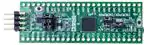
EVAL-ADuCM362QSPZ/EVAL-ADuCM363QSPZ EVALUATION BOARD
Figure 1.
PLEASE SEE THE LAST PAGE FOR AN IMPORTANT
WARNING AND LEGAL TERMS AND CONDITIONS.
Rev. 0 | Page 1 of 6
�UG-1071
ADuCM362/ADuCM363 Getting Started Guide
TABLE OF CONTENTS
Features .............................................................................................. 1
Keil µVision5 ..................................................................................3
Evaluation Kit Contents ................................................................... 1
IAR Embedded Workbench .........................................................4
Online Resources .............................................................................. 1
Elves.exe ..........................................................................................4
General Description ......................................................................... 1
Evaluation Board Setup Procedures ...........................................4
EVAL-ADuCM362QSPZ/EVAL-ADuCM363QSPZ evaluation
board ................................................................................................... 1
Windows Serial Downloader ...........................................................5
Revision History ............................................................................... 2
Downloading Using CM3WSD ...................................................5
Getting Started .................................................................................. 3
Running the Downloaded File ....................................................5
Preparing for Download...............................................................5
Software Installation Procedures ................................................ 3
REVISION HISTORY
10/2016—Revision 0: Initial Version
Rev. 0 | Page 2 of 6
�ADuCM362/ADuCM363 Getting Started Guide
UG-1071
GETTING STARTED
SOFTWARE INSTALLATION PROCEDURES
Perform the steps described in this section before plugging any
USB devices into the PC.
Close all open applications.
Insert the installation DVD into the DVD drive.
Double-click ADuCM36x.exe and follow the on-screen
instructions. A menu displays installation options as shown
in Figure 2.
13967-003
1.
2.
3.
Figure 3. Installing Link Software
If using the IAR tools, the entire contents of the supplied arm
directory (for example, C:\ADuCM36x…\IAR\IAR_M36x_
Patch.zip\arm) must be copied to the IAR tools directory (for
example, C:\Program Files\IAR Systems\ Embedded
Workbench 7.3 Kickstart\arm).
15169-002
Future updates are available from the Analog Devices
FTP website.
Figure 2. Installation Options
The following components install by default:
•
•
Example code and function sets for most peripherals.
An Elves.exe application to easily choose functions from
the provided function sets followed by choosing from the
function parameters.
KEIL µVISION5
The Keil µVision5 integrated development environment (IDE)
integrates all the tools necessary to edit, assemble, and debug
code. The fastest way to start is to open an existing Keil µVision5
project by following these steps:
1.
2.
3.
The following components are optional installations:
•
•
•
Keil development tools (a compiler, debugger, and
programming tools). The Keil μVision 5 software version
is used.
IAR Embedded Workbench development tools (a compiler,
debugger, and programming tools).
Segger J-Link drivers for the J-Link emulator.
4.
5.
15169-009
The J-Link software is selected by default in the installation menu,
shown in Figure 2. It is advised to leave it selected. The J-Link
software automatically installs the J-Link serial port driver. Select
Install USB Driver for J-Link-OB with CDC, shown in Figure 3.
If that step is missed, run JLinkCDCInstaller_V1.2b.exe
located in the ADuCM36x\Segger folder.
In Keil µVision5, select Project > Open Project.
Browse to the folder where the ADuCM362/ADuCM363
software is installed (such as, C:\ADuCM36x...).
Open the file DIO.uvproj in the folder
code\ADuCM362\examples\DIO. This file launches an
example project.
Compile and download to the ADuCM362/ADuCM363 on
the evaluation board.
To run the example code, press RESET on the evaluation
board or enter debug mode by clicking the Start/Stop
Debug Session (Ctrl+F5) button (see Figure 4) and then
click Run (F5) (see Figure 5).
15169-010
Figure 4. Download and Debug Button
Figure 5. Run (F5) Button
6.
Rev. 0 | Page 3 of 6
When running, the red LED marked DISPLAY on the
evaluation board flashes.
�UG-1071
ADuCM362/ADuCM363 Getting Started Guide
3.
IAR EMBEDDED WORKBENCH
The IAR Embedded Workbench integrates all the tools
necessary to edit, assemble, and debug code. The fastest way to
get started is to open an existing workspace by following these
steps:
1.
2.
3.
4.
4.
5.
6.
15169-007
5.
Open the IAR tools from the Start Menu.
Within the IAR IDE, click File > Open > Workspace and
open a workspace provided by Analog Devices (for example,
C:\ADuCM36x…\code\ADuCM362\examples\Blink\DI
O.eww).
Compile and download the code to the device using
Project > Rebuild All and then Project > Download
Active Application.
Click No if a pop-up window appears identifying an
unknown device.
To run the code, press RESET on the evaluation board or
enter debug mode by clicking the Download and Debug
button (see Figure 6) and then click Go (see Figure 7).
Details for installation of the drivers appear on the screen
the first time the user plugs the evaluation board into the
PC or if using a different USB port. Allow the installation
of these drivers to complete as they provide a virtual
communication port on the PC that allows the evaluation
board to appear as a virtual serial communication port to the
UART port of the ADuCM362/ADuCM363 device.
If using the virtual serial communication port to the UART,
ensure Jumpers LK3 and LK5 are in place on the evaluation
board (see Figure 9).
Plug the 10-pin DIL connector of the J-Link OB emulator
into the EVAL-ADuCM362QSPZ or EVALADuCM363QSPZ
The evaluation board is powered by computer from the the
USB cable connected to the J-Link OB emulator. The green
POWER LED turns on.
15169-008
Figure 6. Download and Debug Button
6.
13967-004
Figure 7. Go Button
When running, the red LED marked DISPLAY on the
evaluation board flashes.
Figure 8. Emulator, Top View
ELVES.EXE
Elves.exe is an application that chooses functions from the
provided function sets and function parameters. Elves.exe can
be integrated into the Keil μVision5 and IAR tools under the
tool menus. For instructions, run Elves.exe (for example, at
C:\ADuCM36x…\Software Tools\Elves\Elves.exe) and press the
F1 key or click the Help button.
EVALUATION BOARD SETUP PROCEDURES
Assembling and Connecting the Hardware
Do not plug in the USB cable before the software is installed.
Use the following steps to connect the hardware:
2.
Insert the USB cable provided between the PC and the J-Link
OB emulator (emulator shown in Figure 8).
The red LED (LED1) flashes until initialization of the drivers
completes.
13967-005
1.
Figure 9. J-Link OB Connection Details
Rev. 0 | Page 4 of 6
�ADuCM362/ADuCM363 Getting Started Guide
UG-1071
WINDOWS SERIAL DOWNLOADER
The Windows® Serial Downloader for Cortex-M3-based devices
(named CM3WSD.exe) is a Windows software program that
allows a user to serially download Intel Extended Hex files as
created by assembler/compilers to the ADuCM362/ADuCM363
via the serial port. The Intel Extended Hex file is downloaded
into the on-chip Flash/EE program memory via a selected PC
serial port.
PREPARING FOR DOWNLOAD
2.
3.
4.
5.
6.
1.
2.
3.
4.
Connect the EVAL-ADuCM362QSPZ or EVALADuCM363QSPZ to the USB-SWD/UART-EMUZ
emulator board, and the USB-SWD/UART-EMUZ to the
PC using a USB cable.
Ensure all links are inserted on both boards.
Place the ADuCM362/ADuCM363 into serial download
mode using the following sequence:
Pull the P2.2 pin low.
Pull the RESET pin low and then high (float).
P2.2 can be left floating once the RESET pin is high.
In the software tools \CM3WSD folder, open the file
CM3WSD.exe.
Select the file at C:\ADuCM36x…\code\ADuCM362\
examples\Blink\Obj\Blink.hex.
In the Serial Port drop-down menu, select the JLink
CDC UART Port and a baud rate of 38400.
Select Start. The CM3WSD sends a reset command to
the ADuCM362/ADuCM363. If the ADuCM362/
ADuCM363 is in serial download mode and the COM port
between the PC and the EVAL-ADuCM362QSPZ or EVALADuCM363QSPZ are setup correctly, then the CM3WSD
begins downloading the hex file and displays a progress bar
while the file is downloading. Once the file successfully
downloads, the monitor status box updates with the message
Flashing Complete Click Reset to run program.
RUNNING THE DOWNLOADED FILE
Running Using the CM3WSD
Select Reset with the P2.2 pin floating or pulled high. The
monitor status box updates with the message Running.
Manual Run Option
Pull the RESET pin low, then high (or float) on the EVALADuCM362QSPZ or EVAL-ADuCM363QSPZ to reset the
ADuCM362/ADuCM363, with the P2.2 pin floating or pulled
high. The program starts running automatically.
15169-006
1.
DOWNLOADING USING CM3WSD
Figure 10. Preparing for Download
Rev. 0 | Page 5 of 6
�UG-1071
ADuCM362/ADuCM363 Getting Started Guide
NOTES
ESD Caution
ESD (electrostatic discharge) sensitive device. Charged devices and circuit boards can discharge without detection. Although this product features patented or proprietary protection
circuitry, damage may occur on devices subjected to high energy ESD. Therefore, proper ESD precautions should be taken to avoid performance degradation or loss of functionality.
Legal Terms and Conditions
By using the evaluation board discussed herein (together with any tools, components documentation or support materials, the “Evaluation Board”), you are agreeing to be bound by the terms and conditions
set forth below (“Agreement”) unless you have purchased the Evaluation Board, in which case the Analog Devices Standard Terms and Conditions of Sale shall govern. Do not use the Evaluation Board until you
have read and agreed to the Agreement. Your use of the Evaluation Board shall signify your acceptance of the Agreement. This Agreement is made by and between you (“Customer”) and Analog Devices, Inc.
(“ADI”), with its principal place of business at One Technology Way, Norwood, MA 02062, USA. Subject to the terms and conditions of the Agreement, ADI hereby grants to Customer a free, limited, personal,
temporary, non-exclusive, non-sublicensable, non-transferable license to use the Evaluation Board FOR EVALUATION PURPOSES ONLY. Customer understands and agrees that the Evaluation Board is provided
for the sole and exclusive purpose referenced above, and agrees not to use the Evaluation Board for any other purpose. Furthermore, the license granted is expressly made subject to the following additional
limitations: Customer shall not (i) rent, lease, display, sell, transfer, assign, sublicense, or distribute the Evaluation Board; and (ii) permit any Third Party to access the Evaluation Board. As used herein, the term
“Third Party” includes any entity other than ADI, Customer, their employees, affiliates and in-house consultants. The Evaluation Board is NOT sold to Customer; all rights not expressly granted herein, including
ownership of the Evaluation Board, are reserved by ADI. CONFIDENTIALITY. This Agreement and the Evaluation Board shall all be considered the confidential and proprietary information of ADI. Customer may
not disclose or transfer any portion of the Evaluation Board to any other party for any reason. Upon discontinuation of use of the Evaluation Board or termination of this Agreement, Customer agrees to
promptly return the Evaluation Board to ADI. ADDITIONAL RESTRICTIONS. Customer may not disassemble, decompile or reverse engineer chips on the Evaluation Board. Customer shall inform ADI of any
occurred damages or any modifications or alterations it makes to the Evaluation Board, including but not limited to soldering or any other activity that affects the material content of the Evaluation Board.
Modifications to the Evaluation Board must comply with applicable law, including but not limited to the RoHS Directive. TERMINATION. ADI may terminate this Agreement at any time upon giving written notice
to Customer. Customer agrees to return to ADI the Evaluation Board at that time. LIMITATION OF LIABILITY. THE EVALUATION BOARD PROVIDED HEREUNDER IS PROVIDED “AS IS” AND ADI MAKES NO
WARRANTIES OR REPRESENTATIONS OF ANY KIND WITH RESPECT TO IT. ADI SPECIFICALLY DISCLAIMS ANY REPRESENTATIONS, ENDORSEMENTS, GUARANTEES, OR WARRANTIES, EXPRESS OR IMPLIED, RELATED
TO THE EVALUATION BOARD INCLUDING, BUT NOT LIMITED TO, THE IMPLIED WARRANTY OF MERCHANTABILITY, TITLE, FITNESS FOR A PARTICULAR PURPOSE OR NONINFRINGEMENT OF INTELLECTUAL
PROPERTY RIGHTS. IN NO EVENT WILL ADI AND ITS LICENSORS BE LIABLE FOR ANY INCIDENTAL, SPECIAL, INDIRECT, OR CONSEQUENTIAL DAMAGES RESULTING FROM CUSTOMER’S POSSESSION OR USE OF
THE EVALUATION BOARD, INCLUDING BUT NOT LIMITED TO LOST PROFITS, DELAY COSTS, LABOR COSTS OR LOSS OF GOODWILL. ADI’S TOTAL LIABILITY FROM ANY AND ALL CAUSES SHALL BE LIMITED TO THE
AMOUNT OF ONE HUNDRED US DOLLARS ($100.00). EXPORT. Customer agrees that it will not directly or indirectly export the Evaluation Board to another country, and that it will comply with all applicable
United States federal laws and regulations relating to exports. GOVERNING LAW. This Agreement shall be governed by and construed in accordance with the substantive laws of the Commonwealth of
Massachusetts (excluding conflict of law rules). Any legal action regarding this Agreement will be heard in the state or federal courts having jurisdiction in Suffolk County, Massachusetts, and Customer hereby
submits to the personal jurisdiction and venue of such courts. The United Nations Convention on Contracts for the International Sale of Goods shall not apply to this Agreement and is expressly disclaimed.
©2016 Analog Devices, Inc. All rights reserved. Trademarks and
registered trademarks are the property of their respective owners.
UG15169-0-10/16(0)
Rev. 0 | Page 6 of 6
�


 工商网监
湘ICP备2023018690号
工商网监
湘ICP备2023018690号
