a
FEATURES Very Low Noise 5 nV/÷ Hz @ 1 kHz Max Excellent Input Offset Voltage 75 V Max Low Offset Voltage Drift 1 V/ C Max Very High Gain 1500 V/mV Min Outstanding CMR 106 dB Min Slew Rate 2.4 V/ s Typ Gain Bandwidth Product 5 MHz Typ Industry-Standard 8-Lead Dual Pinout GENERAL DESCRIPTION
Dual Very Low Noise Precision Operational Amplifier OP270
CONNECTION DIAGRAMS 16-Lead SOIC (S-Suffix)
–IN A 1 +IN A 2 NC 3 V– 4 NC 5 +IN B 6 –IN B 7 NC 8
16 OUT A 15 NC 14 NC
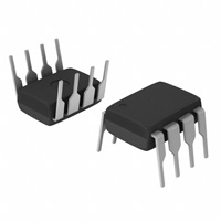
8-Lead PDIP (P-Suffix) 8-Lead CERDIP (Z-Suffix)
OUT A 1 –IN A 2 +IN A 3 V– 4 OP270
A
B
8 7 6 5
V+ OUT B –IN B +IN B
OP270
13 V+ 12 NC 11 NC 10 OUT B 9 NC
The OP270 is a high performance, monolithic, dual operational amplifier with exceptionally low voltage noise, 5 nV/÷Hz max at 1 kHz. It offers comparable performance to ADI’s industry standard OP27. The OP270 features an input offset voltage below 75 mV and an offset drift under 1 mV/∞C, guaranteed over the full military temperature range. Open-loop gain of the OP270 is over 1,500,000 into a 10 kW load, ensuring excellent gain accuracy and linearity, even in high gain applications. Input bias current is under 20 nA, which reduces errors due to signal source resistance. The OP270’s CMR of over 106 dB and PSRR of less than 3.2 mV/V significantly reduce errors due to ground noise and power supply fluctuations. Power consumption of the dual OP270 is one-third less than two OP27s, a significant advantage for power conscious applications. The OP270 is unity-gain stable with a gain bandwidth product of 5 MHz and a slew rate of 2.4 V/ms.
NC = NO CONNECT
The OP270 offers excellent amplifier matching, which is important for applications such as multiple gain blocks, low noise instrumentation amplifiers, dual buffers, and low noise active filters. The OP270 conforms to the industry-standard 8-lead DIP pinout. It is pin compatible with the MC1458, SE5532/A, RM4558, and HA5102 dual op amps, and can be used to upgrade systems using those devices. For higher speed applications, the OP271, with a slew rate of 8 V/ms, is recommended. For a quad op amp, see the OP470.
SIMPLIFIED SCHEMATIC (One of Two Amplifiers Is Shown)
V+
BIAS
OUT
–IN
+IN
V–
REV. C
Information furnished by Analog Devices is believed to be accurate and reliable. However, no responsibility is assumed by Analog Devices for its use, nor for any infringements of patents or other rights of third parties that may result from its use. No license is granted by implication or otherwise under any patent or patent rights of Analog Devices. Trademarks and registered trademarks are the property of their respective companies.
One Technology Way, P.O. Box 9106, Norwood, MA 02062-9106, U.S.A. Tel: 781/329-4700 www.analog.com Fax: 781/326-8703 © 2003 Analog Devices, Inc. All rights reserved.
�OP270–SPECIFICATIONS (V
PARAMETER SYMBOL CONDITIONS
S
=
15 V, TA = 25 C, unless otherwise noted.)
OP270E MIN TYP MAX OP270F MIN TYP MAX MIN OP270G TYP MAX UNIT
Input Offset Voltage Input Offset Current Input Bias Current Input Noise Voltage Input Noise Voltage Density
VOS lOS IB en p-p
en Input Noise Current Density Large-Signal Voltage Gain Input Voltage Range Output Voltage Swing Common-Mode Rejection Power Supply Rejection Ratio Slew Rate Supply Current (All Amplifiers) Gain Bandwidth Product Channel Separation in AVO IVR VO CMR PSRR SR ISY GBP CS
VCM = 0 V VCM = 0 V 0.1 Hz to 10 Hz (Note 1) fO = 10 Hz fO = 100 Hz fO = 1 kHz (Note 2) fO = 10 Hz fO = 100 Hz fO = 1 kHz VO = ± 10 V R L = 1 0 kW RL = 2 kW (Note3) RL ≥ 2 kW VCM = ± 11 V VS = ± 4.5 V to ± 18 V No Load
10 1 5 80 3.6 3.2 3.2 1.1 0.7 0.6 1500 750 ± 12 ± 12 106
75 10 20 200 6.5 5.5 5.0
20 3 10 80 3.6 3.2 3.2 1.1 0.7 0.6 1000 500 ± 12 ± 12 100 1700 900 ± 12.5 ± 13.5 120 1.0 1.7 2.4 4 5
150 15 40 200 6.5 5.5 5.0
50 5 15 80 3.6 3.2 3.2 1.1 0.7 0.6 750 350 ± 12 ± 12 90 1500 700 ± 12.5 ± 13.5 110 1.5 1.7 2.4 4 5
250 20 60
mV nA nA nV p-p nV/÷Hz nV/÷Hz nV/÷Hz pA/÷Hz pA/÷Hz pA/÷Hz V/mV V/mV V V dB
2300 1200 ± 12.5 ± 13.5 125 0.56 3.2
5.6
6
mV/V V/ms mA MHz
1.7
2.4 4 5
6.5
6.5
6.5
VO = ± 20 V p-p fO = 10 Hz (Note 1)
125
175 3 0.4 20
125
175 3 0.4 20 5
175 3 0.4 20 5
dB pF MW GW ms
Input Capacitance Input Resistance Differential-Mode Input Resistance Common-Mode Settling Time
CIN RIN RINCM tS AV = +1, 10 V Step to 0.01%
5
NOTES 1. Guaranteed but not 100% tested. 2. Sample tested. 3. Guaranteed by CMR test. Specifications subject to change without notice.
–2–
REV. C
�SPECIFICATIONS
ELECTRICAL SPECIFICATIONS
PARAMETER SYMBOL
OP270
(Vs = 15 V, –40∞C £ TA £ 85 C, unless otherwise noted.)
OP270E MIN TYP MAX OP270F MIN TYP MAX MIN OP270G TYP MAX UNIT
CONDITIONS
Input Offset Voltage Average Input Offset Voltage Drift Input Offset Current Input Bias Voltage Large-Signal Voltage Gain Input Voltage Range* Output Voltage Swing Common-Mode Rejection Power Supply Rejection Ratio Supply Current (All Amplifiers)
* Guaranteed by CMR test.
VOS TCVOS IOS IB AVO IVR VO CMR PSRR ISY VCM = 0 V VCM = 0 V VO = ± 10 V RL = 10 kW RL = 2 kW RL ≥ 2 kW VCM = ± 11 V VS = ± 4.5 V to ± 18 V No Load
25 0.2 1.5 6 1000 500 ± 12 ± 12 100
150 1 30 60 600 300 ± 12 ± 12 94 5.6 7.2
45 0.4 5 15 1400 700 ± 12.5 ± 13.5 115 1.8 4.4
275 2 40 70 400 225 ± 12 ± 12 90 10 7.2
100 0.7 15 19 1250 670 ± 12.5 ± 13.5 100 2.0 4.4
400 3 50 80
mV mV/∞C nA nA V/mV V/mV V V dB
1800 900 ± 12.5 ± 13.5 120 0.7 4.4
1.5 7.2
mV/V mA
Specifications subject to change without notice.
REV. C
–3–
�OP270
ABSOLUTE MAXIMUM RATINGS 1
Supply Voltage . . . . . . . . . . . . . . . . . . . . . . . . . . . . . . . . ± 18 V Differential Input Voltage2 . . . . . . . . . . . . . . . . . . . . . . ± 1.0 V Differential Input Current2 . . . . . . . . . . . . . . . . . . . . ± 25 mA Input Voltage . . . . . . . . . . . . . . . . . . . . . . . . . . Supply Voltage Output Short-Circuit Duration . . . . . . . . . . . . . . . Continuous Storage Temperature Range P, S, Z Package . . . . . . . . . . . . . . . . . . . . –65°C to +150°C Lead Temperature Range (Soldering, 60 sec) . . . . . . . . 300°C Junction Temperature (TJ) . . . . . . . . . . . . . –65°C to +150°C
Operating Temperature Range OP270E, OP270F, OP270G . . . . . . . . . . . –40°C to +85°C
NOTES 1 Stresses above those listed under Absolute Maximum Ratings may cause permanent damage to the device. This is a stress rating only; functional operation of the device at these or any other conditions above those listed in the operational sections of this specification is not implied. Exposure to absolute maximum rating conditions for extended periods may affect device reliability. 2 The OP270’s inputs are protected by back-to-back diodes. Current limiting resistors are not used, in order to achieve low noise performance. If differential voltage exceeds +10 V, the input current should be limited to ± 25 mA.
ORDERING GUIDE
Model OP270EZ OP270FZ OP270GP OP270GS
TA = +25°C VOS Max ( V) 75 150 250 250
θ JC (°C/W) 12 12 37 27
θ JA* (°C/W) 134 134 96 92
Temperature Range XIND XIND XIND XIND
Package Description 8-Lead CERDIP 8-Lead CERDIP 8-Lead PDIP 16-Lead SOIC
Package Option Q-8 (Z-Suffix) Q-8 (Z-Suffix) N-8 (P-Suffix) RW-16 (S-Suffix)
*θJA is specified for worst-case mounting conditions, i.e., θJA is specified for device in socket for CERDIP and PDIP packages; θJA is specified for device soldered to printed circuit board for SOIC package.
For military processed devices, please refer to the Standard Microcircuit Drawing (SMD) available at www.dscc.dla.mil/programs/milspec/default.asp. SMD Part Number 5962-8872101PA ADI Equivalent OP270AZMDA
CAUTION ESD (electrostatic discharge) sensitive device. Electrostatic charges as high as 4000 V readily accumulate on the human body and test equipment and can discharge without detection. Although the OP270 features proprietary ESD protection circuitry, permanent damage may occur on devices subjected to high energy electrostatic discharges. Therefore, proper ESD precautions are recommended to avoid performance degradation or loss of functionality.
WARNING!
ESD SENSITIVE DEVICE
–4–
REV. C
�Typical Performance Characteristics– OP270
4
AT 10Hz
NOISE VOLTAGE (100nV/DIV)
VOLTAGE NOISE (nV/ Hz)
5 4 3 1/f CORNER = 5Hz 2
VOLTAGE NOISE (nV/ Hz)
10 9 8 7 6
TA = 25 C VS = 15V
5
TA = 25 C
0.1Hz TO 10Hz NOISE
3
AT 1kHz
2
1
1
1
10 100 FREQUENCY (Hz)
1k
0
5 15 10 SUPPLY VOLTAGE (V)
20
TA = 25 C VS = 15V
TIME (1sec/DIV)
TPC 1. Voltage Noise Density vs. Frequency
TPC 2. Voltage Noise Density vs. Supply Voltage
TPC 3. 0.1 Hz to 10 Hz Input Voltage Noise
10
30
CHANGE IN OFFSET VOLTAGE ( A)
TA = 25 C VS = 15V
40 VS = 15V
5 TA = 25 C VS = 15V 4
CURRENT NOISE (pA/ Hz)
VOLTAGE NOISE (nV/ Hz)
20 10 0 –10 –20
3
1.0
2
1/f CORNER = 200Hz
1
0.1 10
100 1k FREQUENCY (Hz)
10k
–30 0 25 50 75 –75 –50 –25 TEMPERATURE ( C)
0
100 125
0
1
2 3 TIME (Minutes)
4
5
TPC 4. Current Noise Density vs. Frequency
TPC 5. Input Offset Voltage vs. Temperature
TPC 6. Warm-Up Offset Voltage Drift
7
5
VS = 15V VCM = 0V
VS = 15V VCM = 0V
7
TA = 25 C VS = 15V
INPUT BIAS CURRENT (nA)
5
3
INPUT BIAS CURRENT (nA)
0 25 50 75 100 125
6
INPUT OFFSET CURRENT (nA)
4
6
5
4
2
4
3
1
3
2 –75 –50 –25
0
25
50
75
100 125
0 –75 –50 –25
TEMPERATURE ( C)
TEMPERATURE ( C)
2 –10.0 –5.0 0.0 5.0 10.0 –12.5 –7.5 –2.5 2.5 7.5 12.5 COMMON-MODE VOLTAGE (V)
TPC 7. Input Bias Current vs. Temperature
TPC 8. Input Offset Current vs. Temperature
TPC 9. Input Bias Current vs. Common-Mode Voltage
REV. C
–5–
�OP270
130 120 110 100 90
CMR (dB)
6
8 7 6 5 4 3 2 1 VS = 15V
TA = 25 C VS = 15V
TOTAL SUPPLY CURRENT (mA)
5
80 70 60 50 40 30 20 10 1 10 100 1k 10k FREQUENCY (Hz) 100k 1M
4
+125 C +25 C
3
–55 C
TOTAL SUPPLY CURRENT (mA)
2
0
5 10 15 SUPPLY VOLTAGE (V)
20
0 –75 –50 –25 25 75 0 50 TEMPERATURE ( C)
100 125
TPC 10. CMR vs. Frequency
TPC 11. Total Supply Current vs. Supply Voltage
TPC 12. Total Supply Current vs. Temperature
140
TA = 25 C 120
140 120
VOLTAGE GAIN (dB)
80
TA = 25 C VS = 15V
CLOSED-LOOP GAIN (dB)
TA = 25 C VS = 15V 60
100
100 80 60 40 20 0
PSR (dB)
80 60 40 20
+PSR
40
–PSR
20
0
0
1
10
100
1k 10k 100k 1M 10M 100M FREQUENCY (Hz)
1
10
100
1k 10k 100k 1M 10M 100M FREQUENCY (Hz)
–20 1k
10k
100k 1M FREQUENCY (Hz)
10M
TPC 13. PSR vs. Frequency
TPC 14. Open-Loop Gain vs. Frequency
TPC 15. Closed-Loop Gain vs. Frequency
25 20 15
GAIN (dB)
PHASE SHIFT (Degrees)
PHASE MARGIN (Degrees)
PHASE
100 120 140
OPEN-LOOP GAIN (V/mV)
4000
70 7
10 GAIN 5 0 –5 PHASE MARGIN = 62
3000
60
6
160 180
2000
50
GBP
5
1000
4
–10
1
2 3 45 FREQUENCY (Hz)
6 7 8 9 10
0
0
5
10 15 SUPPLY VOLTAGE (V)
20
25
40 –75 –50 –25
0 25 50 75 100 125 150 TEMPERATURE ( C)
TPC 16. Open-Loop Gain Phase Shift vs. Frequency
TPC 17. Open-Loop Gain vs. Supply Voltage
TPC 18. Gain-Bandwidth Phase Margin vs. Temperature
–6–
REV. C
GAIN BANDWIDTH PRODUCT (MHz)
TA = 25 C VS = 15V
80
5000
80 8
�OP270
28
PEAK-TO-PEAK AMPLITUDE (V)
24 20 16 12 8 4
TA = 25 C VS = 15V THD = 1%
MAXIMUM OUTPUT ( V)
15
TA = 25 C 14 VS = 15V 13
POSITIVE SWING
50
TA = 25 C VS = 15V VIN = 100mV 40 AV = +1
OVERSHOOT (%)
12 11 10 9 8 7 6 NEGATIVE SWING
30
20
10
0 1k
10k
100k 1M FREQUENCY (Hz)
10M
5 1k
10k LOAD RESISTANCE ( )
100k
0
0
200 600 800 400 CAPACITIVE LOAD (pF)
1000
TPC 19. Maximum Output Swing vs. Frequency
TPC 20. Maximum Output Voltage vs. Load Resistance
TPC 21. Small-Signal Overshoot vs. Capacitive Load
100
2.8
TA = +25 C VS = 15V
VS =
15V
CHANNEL SEPARATION (dB)
190 180 170 160 150 140 130 120 110 100 90 TA = 25 C 80 VS = 15V VO = 20V p-p TO 10kHz 70 10 100 1 1k 10k FREQUENCY (Hz)
2.7
OUTPUT IMPEDANCE ( )
75
AV = 1
SLEW RATE (V/ s)
2.6
50
AV = 10 AV = 100
2.5 –SR 2.4 +SR 2.3
25
0 1k
10k
100k 1M FREQUENCY (Hz)
10M
2.2 –75 –50 –25 25 75 0 50 TEMPERATURE ( C)
100 125
100k
1M
TPC 22. Output Impedance vs. Frequency
TPC 23. Slew Rate vs. Temperature
TPC 24. Channel Separation vs. Frequency
0.1
TA = 25 C VS = 15V VO = 20V p-p RL =2k AV = 10
DISTORTION (%)
0.01
AV = 1
5V
20 s
50mV TA = 25 C VS = 15V AV = +1 RL = 2k 200nS
0.001 10
100 1k FREQUENCY (Hz)
10k
TA = 25 C VS = 15V AV = +1 RL = 2k
TPC 25. Total Harmonic Distortion vs. Frequency
TPC 26. Large Signal Transcient Response
TPC 27. Small-Signal Transient Response
REV. C
–7–
�OP270
5k
TOTAL NOISE AND SOURCE RESISTANCE
The total noise of an op amp can be calculated by:
500 1/2 OP270 V1 20Vp-p
En = where:
(en ) + (in RS ) + (et )
2 2
2
5k
En = total input referred noise en = op amp voltage noise in = op amp current noise
V2 V CHANNEL SEPARATION = 20 log
2 1
50 1/2 OP270
et = source resistance thermal noise RS = source resistance The total noise is referred to the input and at the output would be amplified by the circuit gain. Figure 3 shows the relationship between total noise at 1 kHz and source resistance. For RS < 1 kW the total noise is dominated by the voltage noise of the OP270. As RS rises above 1 kW, total noise increases and is dominated by resistor noise rather than by the voltage or current noise of the OP270. When RS exceeds 20 kW, current noise of the OP270 becomes the major contributor to total noise.
100
V /1000
Figure 1. Channel Separation Test Circuit
+18V
8 100k 2 1/2 OP270 1
3 200k
6 1/2 OP270 7
5 100k
TOTAL NOISE (nV/ Hz)
OP200 10
4
–18V
OP270 RESISTOR NOISE ONLY 1 100 1k 10k 100k
Figure 2. Burn-In Circuit
APPLICATIONS INFORMATION VOLTAGE AND CURRENT NOISE
RS – SOURCE RESISTANCE ( )
The OP270 is a very low noise dual op amp, exhibiting atypical voltage noise of only 3.2 nV/÷Hz @ 1 kHz. The exceptionally low noise characteristic of the OP270 is achieved in part by operating the input transistors at high collector currents since the voltage noise is inversely proportional to the square root of the collector current. Current noise, however, is directly proportional to the square root of the collector current. As a result, the outstanding voltage noise performance of the OP270 is gained at the expense of current noise performance, which is normal for low noise amplifiers. To obtain the best noise performance in a circuit, it is vital to understand the relationship between voltage noise (en), current noise (in), and resistor noise (et).
Figure 3. Total Noise vs. Source Resistance (Including Resistor Noise) at 1 kHz
Figure 4 also shows the relationship between total noise and source resistance, but at 10 Hz. Total noise increases more quickly than shown in Figure 3 because current noise is inversely proportional to the square root of frequency. In Figure 4, current noise of the OP270 dominates the total noise when RS > 5 kW. Figures 3 and 4 show that to reduce total noise, source resistance must be kept to a minimum. In applications with a high source resistance, the OP200, with lower current noise than the OP270, will provide lower total noise.
–8–
REV. C
�OP270
100
TOTAL NOISE (nV/ Hz)
Figure 5 shows peak-to-peak noise versus source resistance over the 0.1 Hz to 10 Hz range. Once again, at low values of RS, the voltage noise of the OP270 is the major contributor to peak-to-peak noise, with current noise the major contributor as RS increases. The crossover point between the OP270 and the OP200 for peak-to-peak noise is at RS = 17 kW. The OP271 is a higher speed version of the OP270, with a slew rate of 8 V/ms. Noise of the OP271 is slightly higher than that of the OP270. Like the OP270, the OP271 is unity-gain stable. For reference, typical source resistances of some signal sources are listed in Table I.
RESISTOR NOISE ONLY
10 OP200
OP270
1 100
Table I.
1k 10k 100k
RS – SOURCE RESISTANCE ( )
Figure 4. Total Noise vs. Source Resistance (Including Resistor Noise) at 10 Hz
Device Strain gage Magnetic tapehead, microphone Magnetic phonograph cartridge
Source Impedance