11/20
2M Micro38999 CONNECTORS
Micro38999
CONNECTORS
For Harsh Environments
Micro38999
2M805 Tri-Start
2M804 Push-Pull
2M803 Bayonet
2M801 Dual-Start
Micro38999
AMPHENOL CORPORATION
40-60 Delaware Avenue, Sidney, NY 13838-1395 • 800-678-0141
www.amphenol-aerospace.com • www.amphenolmao.com
The New
AEROSPACE STANDARD
�About Amphenol Aerospace
Your Source for Interconnect Products
Micro38999
Contact Us:
Amphenol Aerospace
40-60 Delaware Avenue
Sidney, NY 13838-1395
Customer Service:
Mon - Fri 8AM - 5PM
Phone: (800) 678-0141
Fax: (607) 563-5157
Online: www.amphenol-aerospace.com
About Amphenol Aerospace:
Amphenol Aerospace, Amphenol Commercial Air,
and Amphenol Industrial Operations Main Facility in Sidney, NY USA
Amphenol Aerospace, a Division of Amphenol Corporation, is one
of the largest manufacturers of interconnect products in the world for the Military,
Commercial Aerospace and Industrial markets. Amphenol designs, manufactures and
markets circular and rectangular, electronic, fiber optic, EMI/EMP filter, and a variety of
special applications connectors and interconnect systems.
Our state-of-the-art facility is nestled at the foothills of the Catskill Mountains in Sidney,
NY. The Amphenol complex houses many technologies including CNC machining,
die-casting, molding, impact and extruding, plating, screw machining and process
controls. Our fully equipped material evaluation lab and engineering organization utilize
the latest in computer aided design software and analysis tools, allowing us to design,
test, and qualify advanced interconnect systems. Amphenol’s interconnect products are
supplied to thousands of OEMs worldwide and are supported by our worldwide sales
and engineering force, including the largest global network of electronic distributors.
CARE
Customer-Centric:
Our #1 priority is our customers who
deserve quality product on time.
Accountable:
Clear owners, clear
actions, clear results.
Reliable:
What we build matters and
quality is imperative.
Quality Assurance:
Amphenol Aerospace has been awarded
both AS9100 - Revision C and ISO9001:2008
Quality Assurance Certifications.
Enthusiastic:
Challenges create rewarding
opportunities. Enthusiasm is
contagious and we will spread it.
Contact Amphenol Aerospace for more information at 800-678-0141 • www.amphenol-aerospace.com
1
�Micro38999 Reference Guide
A TECHNICAL REFERENCE
2M Series Selection Table
Size & Weight Comparison Chart
Insert Arrangements
Straight PCB Footprints
3
4, 5
6-9
10-20
B PERFORMANCE SPEC
Materials Finishes
Specifications
21-27
C 2M805
Specs/ Info
How to Order
How to Order
Weight
Plug
In-Line Receptacle
Square Flange Receptacle
Jam Nut
PCB Solder Cup Sq Flange
PCB Solder Cup Jam Nut
PCB Standoff Double Flange
How to Order
Protection Cap
2M805 Overview
Plugs & Receptacles
High Speed Plugs & Receptacles
Connector Weight
2M805-001, 002
2M805-003-01, 004-01
2M805-003-02, 004-02
2M805-003-07, 004-07
2M805-005-02, 017-02
2M805-005-07, 017-07
2M805-067-07
Protection Caps
2M667-261, 262
28
29
30
31
32
33
34
35
36
37
38
39
40
2M804 Overview
Plugs & Receptacles
Connector Weight
2M804-001-06, 002-06
2M804-003-07, 004-07
2M804-003-00, 004-00
2M804-003-01, 004-01
2M804-005-07, 020-07
2M804-005-00, 020-00
2M804-009-07, 021-07
2M804-009-00, 021-00
2M804-009-02, 021-02
2M804-025-07
2M667-202
2M809-198
2M809-198, 2M667-202
2M809-083, 087
2M809-083, 087
41
42
43
44
45
46
47
48
49
50
51
52
53
54
55
56
57
58
2M803 Overview
Plugs & Receptacles
Connector Weight
2M803-001-06, 002-06
2M803-003-70, 004-07
2M803-003-02, 004-02
2M803-003-01, 004-01
2M803-005-02, 07
2M660-082, 083
2M660-082, 083
59
60
61
62
63
64
65
66
67
68
D 2M804
Specs/ Info
How to Order
Weight
Plug
Jam Nut Rear Panel
Jam Nut Front Panel
In-Line Receptacle
PCB Solder Rear Jam Nut
PCB Solder Cup Recpt
Jam Nut Panel Mount Plug
Jam Nut Front Panel Plug
Flange Panel Mount Plug
PCB Standoff Double Flange
How to Order Protect Caps
How to Order Protect Caps
Protection Caps
How to Order Plug Rubber
Plug Rubber Caps
E 2M803
Specs/ Info
How to Order
Weight
Plug
Jam Nut
Flange Mount
In-Line Recpt
PCB Flange Mt Jam Nut
How to Order Protect Caps
Protection Caps
2
F 2M801
Specs/ Info
2M801 Overview
How to Order
Plugs & Receptacles
How to Order
High Speed Plugs & Receptacles
Weight
Connector Weight
Plug
2M801-007, 008
Jam Nut
2M801-009-07, 010-07
Square Flange
2M801-009-02, 010-02
In-Line Recpt
2M801-009-01, 010-01
PCB Flange Mt & Jam Nut
2M801-011, 033
PCB Right Angle Jam Nut
2M801-023-07
PCB Standoff Double Flange 2M801-033-07
How to Order Protect Caps 2M667-217, 218
Protection Caps
2M660-082
Protection Caps
2M660-083
69
70
71
72
73
74
75
76
77
78
79
80
81
82
Specs/ Info Hermetic
How to Order 2M805
Flange Mount
Solder Mount
Jam Nut
How to Order 2M804
Jam Nut
Front Panel Jam Nut
How to Order 2M803
Flange Mount/ Jam Nut
How to Order 2M801
Jam Nut
Square Flange
Weld Mount
83
84
85
86
87
88
89
90
91
92
93
94
95
96
G HERMETIC
Overview
2M805-006
2M805-006-02
2M805-006-03
2M805-006-07
2M804-006
2M804-006-07
2M804-006-00
2M803-006
2M803-006-02, 07
2M801-012
2M801-012-07
2M801-012-02
2M801-012-03
H FILTER
Advantages
Overview 97
Attenuation Characteristics 98
J ACCESSORIES
Accessories, Contacts, Tools Table of Content
99
Contact/Tools
Torque Values
100
Assembly Instructions
2M Series
101, 102
Sealing Plugs/ Tools
Grommet, Spanner, Holding
103. 104
Strain Relief Clamp
2M620MS064, 065
105, 106
Micro Band Adapter
Thread/ Low Profile
107, 110
Environmental Backshells 111-112
EMI Backshells 113-117
Shorting Cap Backshell
118, 119
Shrink Boot
2M809S06, 2M809A060
120, 121
Hex Jam Nuts
2M809-035
122
Flange Gaskets
2M809-106
123, 124
O-Ring
2M809-109 125
Contact Amphenol Aerospace for more information at 800-678-0141 • www.amphenol-aerospace.com
�2M Series Selection Table
2M801, 2M803, 2M804 and 2M805
Micro38999
Technical
Reference
2M805
2M804
2M803
2M801
Pages 28-39
Pages 40-57
Pages 58-67
Page 68-80
SERIES
Pages
TYPE
Tri-Start ACME Thread
Push-Pull
Bayonet
Dual-Start ACME Thread
DESCRIPTION
"Anti-Decoupling"
ratchet mechanism and
ground spring for military
airframes and avionics
boxes. Fast mating.
Breakaway connector
for headsets and tactical
equipment. Gold-plated
spring for long mating life
and superior EMI shielding.
Quick-mating, light duty,
general purpose. Not rated
for immersion, 50 milliohms
shell-to-shell
resistance.
More rugged keys and
threads. Faster mating.
CONTACTS
1 to 130
1 to 85
1 to 55
1 to 130
COUPLING
Tri-Start Thread
Push, Pull
Quick-Disconnect
1/4 turn lock Bayonet
Threaded Coupling with 1
1/2 Turns to Full Mate
WATER
IMMERSION, MATED
MIL-STD-810 Method 512
1 Meter for 1 Hour
MIL-STD-810 Method 512
1 Meter for 1 Hour
Splashproof
MIL-STD-810 Method 512 1
Meter for 1 Hour
EMI
SHIELDING
Excellent
Excellent
Fair
Very Good
VIBRATION AND
SHOCK
43.9 g's Random
37 g's Random
Vibration, Sine Vibration 60
Vibration; 300 g's Shock
g; 300 g's Shock
37 g's Random
Vibration; 300 g's Shock
43.9 g's Random Vibration,
Sine Vibration 60 g; 300 g's
Shock
MATING CYCLES
500 Cycles
2000 Cycles
1000 Cycles Aluminum
2000 Cycles Stainless
Steel
2000 Cycles (-16 Plugs)
500 Cycles (-26 Plugs)
ELECTRICAL
PERFORMANCE
#12: 23 AMP, 1800 VAC
#16: 13 AMP, 1800 VAC
#20: 7.5 AMP, 1000 VAC
#23: 5 AMP, 750 VAC
#12: 23 AMP, 1800 VAC
#16: 13 AMP, 1800 VAC
#20: 7.5 AMP, 1000 VAC
#23: 5 AMP, 750 VAC
#12: 23 AMP, 1800 VAC
#16: 13 AMP, 1800 VAC
#20: 7.5 AMP, 1000 VAC
#23: 5 AMP, 750 VAC
#12: 23 AMP, 1800 VAC
#16: 13 AMP, 1800 VAC
#20: 7.5 AMP, 1000 VAC
#23: 5 AMP, 750 VAC
FILTERED
See pages 95, 96
See pages 95, 96
See pages 95, 96
See pages 95, 96
Contact Amphenol Aerospace for more information at 800-678-0141 • www.amphenol-aerospace.com
A
3
�Size & Weight Comparison Charts
Technical
Reference
2M805 VS. D38999 Series III
2M801
6-7
2M805
8-7
2M805 Series
Weight Comparison: 2M805 VS. D38999 Series III
2M805
Layout
8-7
10-13
11-19
12-26
15-37
18-55
19-85
23-130
Number of D38999
Contacts Layout
7 #23
13 #23
19 #23
26 #23
37 #23
55 #23
85 #23
130 #23
9-35
11-35
13-35
17-26
15-35
17-35
21-35
25-35
Number of
Contacts
6 #20
13 #22D
19 #22D
26 #20
37 #22D
55 #22D
85 #22D
128 #22D
2M805
D38999
% Weight
D38999 % Weight
Weight Aluminum Savings Composite Savings
13.4
23.0
26.4
29.4
42.7
59.6
59.8
85.5
26.3
35.7
50.7
58.5
72.1
81.6
119.7
159.3
49%
36%
48%
50%
41%
27%
50%
46%
19.9
26.8
38.5
62.6
57.4
65.6
99.1
136.6
33%
14%
31%
53%
26%
9%
40%
37%
Size Comparison: 2M805 VS. D38999 Series III
2M805
Layout
8-7
10-13
11-19
12-26
15-37
18-55
19-85
23-130
Maximum Jam Nut Receptacle
Diameter
Maximum Plug Diameter
2M805
D38999
2M805
D38999
In.
mm.
In.
mm.
%
Reduction
In.
mm.
In.
mm.
%
Reduction
.707
.804
.933
.999
1.113
1.308
1.328
1.577
17.96
20.42
23.70
25.37
28.27
33.02
33.73
40.06
.859
.969
1.141
1.391
1.266
1.391
1.625
1.875
21.81
24.61
28.98
35.33
32.16
35.33
41.27
47.63
17%
18%
20%
29%
13%
7%
19%
16%
.775
.895
.960
1.075
1.218
1.404
1.465
1.720
19.69
22.73
24.38
27.31
30.86
35.66
37.21
43.69
1.201
1.386
1.512
1.764
1.638
1.764
2.075
2.323
30.51
30.50
38.40
44.81
41.61
44.81
52.71
59.00
35%
35%
36%
39%
26%
20%
29%
26%
Note: Weights shown include contacts and represent a mated pair of plug and jam nut receptacle.
Weights are in grams.
A
4
Contact Amphenol Aerospace for more information at 800-678-0141 • www.amphenol-aerospace.com
D38999
9-35
�Size & Weight Comparison Charts
2M801 VS. D38999 Series III
Micro38999
2M805
8-7
D38999
9-35
Technical
Reference
2M801
6-7
2M801 Series
Weight Comparison: 2M801 VS. D38999 Series III
2M801
Layout
Number of
Contacts
D38999
Layout
5-3
6-7
9-19
13-37
16-55
17-85
21-130
3
7
19
37
55
85
130
9-98
9-35
13-35
15-35
17-35
21-35
25-35
Number of 2M801
D38999
Contacts Weight Aluminum
3
6
22
37
55
79
128
7.9
9.8
18.8
36.0
49.8
54.3
68.7
25.3
26.3
50.7
72.1
81.6
119.7
159.3
% Weight
D38999 % Weight
Savings Composite Savings
69%
63%
63%
50%
39%
55%
57%
19.9
19.9
38.5
57.4
65.6
99.1
136.6
60%
51%
51%
37%
24%
45%
50%
Size Comparison: 2M801 VS. D38999 Series III
2M801
Layout
5-3
6-7
9-19
13-37
16-55
17-85
21-130
Cable Plug Diameter
2M801
In.
mm.
.540
.600
.810
1.050
1.240
1.300
1.550
13.72
15.24
20.57
26.67
31.50
33.02
39.37
D38999
In.
mm.
.859
.859
1.156
1.281
1.406
1.641
1.890
21.82
21.82
29.36
32.54
35.71
41.68
48.01
Jam Nut Receptacle Diameter
%
Reduction
37%
30%
30%
18%
12%
21%
18%
2M801
In.
mm.
.575
.635
.830
1.078
1.264
1.325
1.625
14.61
16.13
21.08
27.38
32.11
33.66
41.28
D38999
In.
mm.
1.204
1.204
1.516
1.641
1.766
2.078
2.323
30.58
30.58
38.51
41.68
44.86
52.78
59.00
%
Reduction
52%
47%
45%
34%
28%
36%
30%
Note: Weights shown include contacts and represent a mated pair of plug and jam nut receptacle.
Weights are in grams.
A
Contact Amphenol Aerospace for more information at 800-678-0141 • www.amphenol-aerospace.com
5
�2M Series Technical Information
Technical
Reference
Inserts Arrangements
SERIES 2M INSERT ARRANGEMENTS
CONTACT SIZE
Size #23 Contacts
5 Amp Max.
Current 750 VAC
#22-#28 AWG
#23
CONTACT QUANTITY
#20
#20HD
#16
#12
3
5-3
5-3
5-3
NA
4
6-4
6-4
6-4
8-4
6
6-6
6-6
6-6
8-6
7
6-7
6-7
6-7
8-7
10
7-10
7-10
7-10
9-10
13
8-13
8-13
8-13
10-13
19
9-19
9-19
9-19
11-19
26
10-26
10-26
10-26
12-26
37
13-37
12-37
12-37
15-37
55
16-55
14-55
14-55
18-55
85
17-85
15-85
15-85
19-85
23-130
130
Size #20HD
Contacts
7.5 Amp Max.
Current
1000 VAC
#20-#24 AWG.
Size #16 Contacts
13 Amp Max.
Current 1800 VAC
#16-#20 AWG
21-130
NA
NA
3
6-23
6-23
6-23
8-23
5
7-25
7-25
7-25
9-25
8
8-28
8-28
8-28
10-28
10
9-210
9-210
9-210
11-210
20
13-220
12-220
12-220
15-220
35
16-235
14-235
14-235
18-235
41
17-241
NA
NA
19-241
69
21-269
NA
NA
23-269
1
6-1
6-1
6-1
8-1
2
8-2
8-2
8-2
10-2
4
9-4
9-4
9-4
11-4
5
10-5
10-5
10-5
12-5
7
13-7
12-7
12-7
15-7
12
16-12
14-12
14-12
18-12
14
17-14
15-14
15-14
19-14
22
21-22
NA
NA
23-22
1
7-1
7-1
7-1
9-1
2
10-2
10-2
10-2
12-2
Size #12 Contacts
23 Amp Max.
Current
1800 VAC
#12-14 AWG
Insert
Arrangements
with Mixed Size
(Combo) Layouts
INSERT ARRANGEMENT
2M801 2M803 2M804 2M805
4
2
8
2
2
13-2
12-2
12-2
15-2
3
13-3
12-3
12-3
15-3
5
16-5
14-5
14-5
18-5
7
17-7
15-7
15-7
19-7
12
21-12
NA
NA
23-12
8-200
8-200
8-200
10-200
9-201
9-201
9-201
11-201
4
2
9-200
9-200
9-200
11-200
8
2
10-202
10-202
10-202
12-202
10-201
10-201
10-201
12-201
4
2
6
2
13-200
12-200
12-200
15-200
10
2
13-201
12-201
12-201
15-201
12
1
10-200
10-200
10-200
12-200
A
6
Contact Amphenol Aerospace for more information at 800-678-0141 • www.amphenol-aerospace.com
�2M Series Technical Information
Insert Arrangements
Micro38999
Technical
Reference
Front face of pin inserts illustrated (Socket Reversed)
CONTACT LEGEND 12
A
2
1
B
4
C
6
2
3
4
1
5
3
2
3
4
1
6
7
5
16
20
1
20HD
20
23
2
3
7
2
4
10
3
1
8
9
2M801 2M803 2M804
5-3
6-1*
6-4
6-6
6-7
6-23
7-1*
7-10
2M805
NA
8-1*
8-4
8-6
8-7
8-23
9-1*
9-10
3
1
4
6
7
3
1
10
No. of Contacts
Contact Size
#23
#16
#23
#23
#23
#20HD
#12
#23
DWV Voltage (VAC)
750
1800
750
750
750
1000
1800
750
5
13
5
5
5
7.5
23
5
Current Rating (Amps)
1
2
2
9
3
10
1
3
5
4
2 8 1
4 11 5
2
1
7 13
6
12
7
6
5
7-25
8-2
8-13
8-28
2M805
9-25
10-2
10-13
10-28
5
2
13
8
#20HD
#16
#23
1000
1800
750
7.5
13
5
Contact Size
DWV Voltage (VAC)
Current Rating (Amps)
3 2 1
7
12
16
8
19 18 17
2M801 2M803 2M804
9-19
2M805
11-19
No. of Contacts
19
Contact Size
DWV Voltage (VAC)
4
1
2
4
4
13
9-200
11-200
#20HD
#20
#23
#16
1000
1000
750
1800
7.5
7
5
13
2
8
9
7
7
8
2
1
1
4
3
10
4
6
2
1
5
9-210
10-2
12-2
10
2
#23
#20
#23
#20HD
#12
750
1000
750
1000
1800
5
7.5
5
7.5
23
#16
5
13
2
3
1
4
3
6
4
11-4
11-210
1800
3
9-4
8
750
5
3
4
11-201
#23
2
4
3
2
4
1
5
2
10-200*
9-201
2
Current Rating (Amps)
9
6
1
8-200*
5
10
5
1
2
6
3
6
3
2
4
4
2M801 2M803 2M804
No. of Contacts
3
8
12 1
2
4
6
5
7
9
5
1
10
9
8
2
11
10
3
4
8
7
6
2M801 2M803 2M804
10-5
10-201
10-202*
10-200*
2M805
12-5
12-201
12-202*
12-200*
No. of Contacts
5
2
4
2
8
5
1
12
Contact Size
#16
#12
#23
#16
#23
#12
#23
DWV Voltage (VAC)
1800
1800
750
1800
750
1800
750
13
23
5
13
5
23
5
Current Rating (Amps)
Contact Amphenol Aerospace for more information at 800-678-0141 • www.amphenol-aerospace.com
A
7
�2M Series Technical Information
Technical
Reference
Insert Arrangements
Front face of pin inserts illustrated (Socket Reversed)
CONTACT LEGEND 12
6
3 1 2
11
15
18
23
25 26 24
20HD
2
1
9
12
16
21
6
3
5
2
3
2
7
4
13-2
13-3*
13-7
2M803 2M804
10-26
12-2
12-3*
12-7
2M805
12-26
15-2
15-3*
15-7
No. of Contacts
26
2
3
7
Contact Size
#23
#12
#12
#16
DWV Voltage (VAC)
750
1800
1800
1800
5
23
23
13
15
22
28
33
1
4
37
34
2
3
5
10
16
23
29
4
5 2 1 3
1
4
5
8
7
7
6
10
6
12 9 11
11
10
8
2
1
13
12
19
3
4
15
14
16
20
5
18
17
9
8
13-37
13-200*
13-201
13-220
2M803 2M804
12-37
12-200
12-201
12-220
2M805
15-37
15-200*
15-201
15-220
No. of Contacts
37
2
6
2
10
20
Contact Size
#23
#12
#23
#12
#23
#20HD
DWV Voltage (VAC)
750
1800
750
1800
750
1000
5
23
5
23
5
7.5
1
2
5
9
3
16
24
31
39
46
52
3 2 1
2
4
10
17
25
32
40
47
5
1
30
3
4
8 7
9
12
6
7
2M801
Current Rating (Amps)
6
18 1
20
5
15
35
10
10
4
55 54 53
2M801
16-5
16-55
16-12
16-235
2M803 2M804
14-5
14-55
14-12
14-235
2M805
18-5
18-55
18-12
18-235
5
55
12
35
No. of Contacts
11
25
Contact Size
#12
#23
#16
#20HD
DWV Voltage (VAC)
1800
750
1800
1000
23
5
13
7.5
Current Rating (Amps)
23
1
1
4
20
10-26
9
8
20
2M801
Current Rating (Amps)
A
16
*Not tooled for every insert pattern
Contact Amphenol Aerospace for more information at 800-678-0141 • www.amphenol-aerospace.com
�2M Series Technical Reference
Insert Arrangements
Micro38999
CONTACT LEGEND 12
1
2
2
3
5
2M801
17-7
2M803 2M804
2M805
38
47
57
66
74 81
6
12
10
13
14
20HD
20
23
1
4
19 11
28
3
9
4
20
1
5
7
6
16
82
85
17-14*
17-85
15-7
15-14
15-85
19-7
19-14*
19-85
No. of Contacts
7
14
85
Contact Size
#12
#16
#23
DWV Voltage (VAC)
1800
1800
750
23
13
5
Current Rating (Amps)
2
20 1
3
21
4
34 35 22
17 32
36 23 6
41
16 31 40
37 24 7
30
15
33
39
14
26
38
29 28 27
13
12 11
8
4
5
2
19
18
1
3
5
13
6
25
1
9
5
9
10
14
18
9
12
10
22
10
19
11
2M801
17-241*
21-12
21-22*
2M805
19-241*
23-12
23-22*
41
12
22
No. of Contacts
Contact Size
DWV Voltage (VAC)
Current Rating (Amps)
#20HD
#12
#16
1000
1800
1800
7.5
23
13
25 15
36
6
1
48
59
71
82
94
105
115 124
7 16
26
37
49
60
72
95 83
116 106
125
130
1
25
24
23
45
44
43
58
21
42
57
67
56
17
49
63
52 34
53
37
35
14
11
10
13
15
21-130
21-269
2M805
23-130
23-269
130
69
Contact Size
#23
#20HD
DWV Voltage (VAC)
750
1000
5
7.5
Current Rating (Amps)
9
12
36
16
8
32
51 33
65
54
38
7
31
50
64
55
39
18
69
66
6
30
62
68
40
19
29
48
60 61
59
22
47
5
4
28
27
46
41
20
3
2
26
2M801
No. of Contacts
5 12
20
29
39
48
58
75 67
Technical
Reference
Front face of pin inserts illustrated (Socket Reversed)
*Not tooled for every insert pattern
Contact Amphenol Aerospace for more information at 800-678-0141 • www.amphenol-aerospace.com
A
9
�2M Series Technical Information
Technical
Reference
Straight PCB Footprints
INSERT ARRANGEMENT
A
PIN CONNECTOR
B
.038
C
A
.020
B
5-3
(3) #23 Contacts
.022 Max. Dia Tall
1
SOCKET CONNECTOR
C
A
B
C
.044
.053
2
3
.031
6-23, 8-23
(3) #20HD Contacts
.023 Max. Dia. Tail
.061
1
3
4
.038
3
6-4, 8-4
(4) #23 Contacts
.022 Max. Dia Tail
6
5
7
10
2
3
.038
1
2
.066
.076
.038
1
6
2
3
4
5
4
7-10, 9-10
10 #23 Contacts
.022 Max. Dia. Tail
.066
1
3
4
2
1
6
4
5
2
1
7 6
3
7 3
4
4
1
4
4
7
10
.076
3
2
5
.114
3
8
3
2
.038
1
4
9
4
5
6-7, 8-7
(7) #23 Contacts
.022 Max. Dia. Tail
3
7
2
6
6-6, 8-6
(6) #23 Contacts
.022 Max. Dia. Tail
1
1
.076
.038
2
3
4
1
5
6
3
2
1
1
2
2
8
.066
1
3
7
8 10
Socket inserts are a mirror image of pin side. Socket side shown for cavity locations only, reference pin side for dimensions.
A
10
Contact Amphenol Aerospace for more information at 800-678-0141 • www.amphenol-aerospace.com
�2M Series Technical Reference
Straight PCB Footprints
Micro38999
PIN CONNECTOR
.086
1
SOCKET CONNECTOR
.053
2
.073
3
5
1
2
4
5
7-25, 9-25
(5) #20HD Contacts
.028 Max. Dia Tall
4
3
1
2
3
.028
.090
Technical
Reference
INSERT ARRANGEMENT
4
5
.085
2
1
8-2, 10-2
(2) #16 Contacts
.119
.096
.053
2
1
7
3
8
6
4
5
1
7
.110
2
3
8
6
.122
.027
2
3
.076
4
4
5
1
8 7
6
5
8-28, 10-28
(8) #20HD Contacts
.038
.070
2
1
4
3
6
5
2 8 1
4 11 5
3
4
8-200*, 10-200*
(2) #20 Contacts
(4) #23 Contacts
9
3
10
1
2
7 13
6
12
8-13, 10-13
(13) #23 Contacts
.022 Max. Dia. Tail
6
5
2
.114 .076
3
.038
8
9 13
10
4
.132
.124
1
2
3
4
5
6
2
8
6 7 13 9 3
10
12
11
5 4
1
1
7 6
12
11
5
.066
.0885
1
2
4
3
9-4, 11-4
(4) #16 Contacts
1
2
2
1
4
3
3
4
.0885
*Not tooled for every insert pattern
Contact Amphenol Aerospace for more information at 800-678-0141 • www.amphenol-aerospace.com
A
11
�2M Series Technical Information
Technical
Reference
Straight PCB Footprints
INSERT ARRANGEMENT
PIN CONNECTOR
SOCKET CONNECTOR
.038
.085
1
2
2
4
1
3
3
4
5
6
9-200, 11-200
(4) #23 Contacts
(2) #16 Contacts
6
2
1
.142
4
3
5
5
6
.114
.038
4
3
2
5
6
10
9
8
3
4
1
2
.124
5
6
7
9
10
9-201, 11-201
(2) #20 Contacts
(8) #23 Contacts
3
4
6
5
7
8
2
1
1
8
7
9
10
.070
.133
.053
1
2
8
9
7
3
10
4
6
.140
8
9
5
.070
7
9-210*, 11-210*
(10) #20HD Contacts
2
2
1
3
10
10
4
4
6
1
3
9
8
7
5
6
5
.152
7
12
16
3 2 1
.114
.076
.038
4
8
19 18 17
13
9-19, 11-19
(19) #23 Contacts
.022 Max. Dia Tail
1
3
7
.132
8
12
16
13
19
3
1
4
.066
4
7
12
16
8
13
17
17
19
.125
2
1
2
A
12
1
1
10-2, 12-2
(2) #12 Contacts
*Not tooled for every insert pattern
Contact Amphenol Aerospace for more information at 800-678-0141 • www.amphenol-aerospace.com
2
�2M Series Technical Reference
Straight PCB Footprints
Micro38999
PIN CONNECTOR
.138
2
1
.085
1
3
5
SOCKET CONNECTOR
Technical
Reference
INSERT ARRANGEMENT
.117
2
2
1
4
.145
5
3
10-5, 12-5
(5) #16 Contacts
2
3
.156
6
5
7
5
.156
.118
1
3
4
10-202*, 12-202*
(2) #16 Contacts
(8) #23 Contacts
.194
9
5
6
11
15
18
23
25 26 24
6
7
8
8
9
10
.149
10-26, 12-26
(26) #23 Contacts
.022 Max. Dia. Tail
2 1
2
.086 10
4
4
9
5
5
8
6
11
15
18
3
23
1
26
.197
.132
.066
11
10
9
6
6
7
12
3
3
4
9
12
16
21
1
11
.172
3 1 2
3
5
10
12
10-200*, 12-200*
(1) #12 Contact
(12) #23 Contacts
6
1
4
5
7
9
2
3
4
7
6
.172
.149
.086
11
10
8
2
2
6
12 1
4
3
5
8
10
2
.085
.066
2
4
9
1
3
4
10-201, 12-201
(2) #12 Contacts
(4) #23 Contacts
6
1
2
5
1
4
.115
.038
4
3
5
.045
4
1
6
3
.076 .152
2
4
7
9
12
16 .038 .114
.190
21
12
4
9
2
8
7
1
6
11
15
18
23
16
21
3
26
*Not tooled for every insert pattern
Contact Amphenol Aerospace for more information at 800-678-0141 • www.amphenol-aerospace.com
A
13
�2M Series Technical Information
Technical
Reference
Straight PCB Footprints
2
INSERT ARRANGEMENT
PIN CONNECTOR
SOCKET CONNECTOR
.125
.125
2
1
2
1
1
2
1
12-2, 13-2, 15-2
(2) #12 Contacts
1
1
1
.135
2
3
.070
2
2
3
3
.115
12-3*, 13-3*, 15-3*
(3) #12 Contacts
.147
1
1
6
6
2
7
.085
4
.170
3
5
3
4
12-7, 13-7, 15-7
(7) #16 Contacts
6
7
7
3
5
1
2
2
5
4
.147
.115
.066
3
2
1
4
5
8
7
6
1
1
3
2
2
4
5
A
14
8
4
5
.128
.166
7
12-200*, 13-200*, 15-200*
(2) #12 Contacts
(6) #23 Contacts
3
6
7
6
*Not tooled for every insert pattern
Contact Amphenol Aerospace for more information at 800-678-0141 • www.amphenol-aerospace.com
8
�2M Series Technical Reference
Straight PCB Footprints
Micro38999
PIN CONNECTOR
4
5 2 1 3
.236
7
.115
.076
.038
.170
2
5
6
10
12 9 11
11
4
5
18
10
17
9
12 19
20
11 10
.092
18
8
7
6
12-220, 13-220, 15-220
(20) #20HD Contacts
9
15
22
28
33
1
4
37
34
4
16
17
8
.221
.196
.114
.076
.038
5
10
16
23
29
9
.026
.126
5
4
15
16
6
7
7
12
2
3
5
6
1
13
14
20
17
8
.106
.182
.220
12
11
19
18 10
9
.228
.190
.152
1
4
5
15
22
28
33
12-37, 13-37, 15-37
(37) #23 Contacts
.022 Max. Dia. Tail
.079
3
9
9 10
11
15
14
7
8
.207
.147
.053
1 2
2
4 5
6
8
.106
3
16
20
3
11
13
15
14
19
9
12
.166
13
12
4 3
6
10
.215
2
1
1
7
8
12-201, 13-201, 15-201
(2) #12 Contacts
(10) #23 Contacts
1
SOCKET CONNECTOR
Technical
Reference
INSERT ARRANGEMENT
34
37
1
4
5
.197
10
.132
16
10
16
23 .066
29
23
29
34
9
15
22
28
33
37
.115
1
1
2
2
1
2
.159
5
3
.195
.060
3
5
5
3
4
4
4
14-5, 16-5, 18-5
(5) #12 Contacts
.186
Contact Amphenol Aerospace for more information at 800-678-0141 • www.amphenol-aerospace.com
A
15
�2M Series Technical Information
Technical
Reference
Straight PCB Footprints
INSERT ARRANGEMENT
PIN CONNECTOR
SOCKET CONNECTOR
.255
.170
.085
2
5
1
2
3
4
8 7
9
12
5
.241
6
11
8
12
7
10
11
2
1
3
4
9
.094
10
1
3
.054
6
4
5
6
.201
10
9
8
7
12
11
14-12, 16-12, 18-12
(12) #16 Contacts
9
16
24
31
39
46
52
3 2 1
4
10
17
25
32
40
47
55 54 53
16 9
24
31
39
46
18 1
20
55
4
10
17
25
32 .066
40
.132
47
.197
53
.263
10
17
25
32
40
2
18 1
3
30 19 20 4
16
21 5
29 35 31
22
28
15
34
32 23 6
14
33
7
27 26
24
13
8
25
12
9
10
11
17
5
15
52
.076
.152
.228
14-55, 16-55, 18-55
(55) #23 Contacts
.022 Max. Dia. Tail
30
3
.266
.190
.114
.038
1
4
35
10
25
14-235, 16-235, 18-235
(35) #20HD Contacts
.023 Max. Dia. Tail
4
1
3
53
55
47
3 2
20
5 21
22
6
23
7
24
8
9
1
19
30
31 35
32
33
34
9
16
24
31
39
46
52
18
17
29 16
28
27
26
10 25
12
11
15
14
13
14-235, 16-235, 18-235
A
16
X
Y
X
Y
X
Y
Pin.
No.
in.
mm.
in.
mm.
Pin.
No.
in.
mm.
in.
mm.
Pin.
No.
in.
mm.
in.
mm.
1
-.053
-1.35
.301
7.65
13
-.234
-5.94
-.196
-4.98
25
.000
0.00
-.209
-5.31
2
.053
1.35
.301
7.65
14
-.287
-7.29
-.104
-2.64
26
-.100
-2.54
-.172
-4.37
3
.153
3.89
.264
6.71
15
-.305
-7.75
.000
0.00
27
-.181
-4.60
-.104
-2.64
4
.234
5.94
.196
4.98
16
-.287
7.29
.104
2.64
28
-.199
-5.05
.000
0.00
5
.287
7.29
.104
2.64
17
-.234
-5.94
.196
4.98
29
-.181
-4.60
.104
2.64
6
.305
7.75
.000
0.00
18
-.153
-3.89
.264
6.71
30
-.100
-2.54
.172
4.37
7
.287
7.29
-.104
-2.64
19
.000
0.00
.209
5.31
31
-.053
-1.35
.073
1.85
8
.234
5.94
-.196
-4.98
20
.100
2.54
.172
4.37
32
.053
1.35
.073
1.85
9
.153
3.89
-.264
-6.71
21
.181
4.60
.104
2.64
33
.086
2.18
-.028
-0.71
10
.053
1.35
-.301
-7.65
22
.199
5.05
.000
0.00
34
.000
0.00
-.090
-2.29
11
-.053
-1.35
-.301
-7.65
23
.181
4.60
-.104
-2.64
35
-.086
-2.18
-.028
-0.71
12
-.153
-3.89
-.264
-6.71
24
.100
2.54
-.172
-4.37
Contact Amphenol Aerospace for more information at 800-678-0141 • www.amphenol-aerospace.com
�2M Series Technical Reference
Straight PCB Footprints
Micro38999
PIN CONNECTOR
SOCKET CONNECTOR
Technical
Reference
INSERT ARRANGEMENT
.230
.115
1
2
.199
7
6
1
2
5
7
6
4
1
2
3
3
3
6
7
4
5
5
4
15-7, 17-7, 19-7
(7) #12 Contacts
.255
.170
.085
.294
2
1
2
5
3
9
6
12
8
9
.147
10
3
6
7
11
12
13
14
3
4
5
4
6
5
8
7
9
11
10
10
14
2
1
1
12
13
13
14
15-14, 17-14, 19-14
(14) #16 Contacts
20
20 1
2
19
18
21
33
34 35
17 32
30
15
16
41
31 40
39
14
3
29 28 27
13
7
37 24
12 11
26
18
17
6
36 23
38
19
5
4
22
8
32
1
2
33
21
34
31
9
30
16
10
15
17-241, 19-241
(41) #20HD Contacts
.028 Max. Dia. Tail
14
24
37
39
13
23
36
41
38
29
28
5
11
8
9
32 18
34
37
40
31
39
16
30
38
27
10
19
33
41
26
9
10
36
25
7
8
26
35
23
24
6
7
25
27
12
6
22 21
4
5
1
20
2
3
4
22
35
40
25
3
28
11
12
29
17
15
14
13
17-241, 19-241
Pin.
No.
1
2
3
4
5
6
7
8
9
10
11
12
13
14
X
in.
-.053
.053
.154
.240
.302
.335
.335
.302
.240
.154
+ .053
-.053
-.154
-.240
Y
mm.
-1.35
1.35
391
6.10
7.67
8.51
8.51
7.67
6.10
3.91
+1.35
-1.35
-3.91
-6.10
in.
.335
.335
.302
.240
.154
.053
-.053
-.154
-.240
-.302
-.335
-.335
-.302
-.240
mm.
8.51
8.51
7.67
6.10
3.91
1.35
-1.35
-3.91
-6.10
-7.67
-8.51
-6.51
-7.67
-6.10
Pin.
No.
15
16
17
18
19
20
21
22
23
24
25
26
27
28
X
in.
-.302
-.335
-.335
-.302
-.240
-.154
.000
.106
.188
.226
.213
.151
.055
-.055
Y
mm.
-7.67
-8.51
-8.51
-7.67
-6.10
-3.91
0.00
2.69
4.78
5.74
5.41
3.84
1.40
-1.40
in.
-.154
-.053
.053
.154
.240
.302
.228
.202
.130
.028
-.081
-.171
-.222
-.222
mm.
-3.91
-1.35
1.35
3.91
6.10
7.67
5.79
5.13
3.30
0.71
-2.06
-4.34
-5.64
-5.64
Pin.
No.
29
30
31
32
33
34
35
36
37
38
39
40
41
X
in.
-.151
-.213
-.226
-.188
-.106
-.053
.053
.119
.096
.000
-.096
-.119
.000
Y
mm.
-3.84
-5.41
-5.74
-4.78
-2.69
-1.35
1.35
3.02
2.44
0.00
-2.44
-3.02
0.00
in.
-.171
-.081
.028
.130
.202
.110
.110
.027
-.076
-.122
-.076
.027
.000
Contact Amphenol Aerospace for more information at 800-678-0141 • www.amphenol-aerospace.com
mm.
-4.34
-2.06
0.71
3.30
5.13
2.79
2.79
0.69
-1.93
-3.10
-1.93
0.69
0.00
A
17
�2M Series Technical Information
Technical
Reference
Straight PCB Footprints
INSERT ARRANGEMENT
PIN CONNECTOR
SOCKET CONNECTOR
.342
.266
.190
.114
.038
.330
19 11
28
38
47
57
66
74 81
1
4
82
85
5 12
20
29
39
48
58
75 67
.132
4
1
4
1
20
20
28
47
39
28
39
47
58
66
.264 .198 .066
58
66
85
82
82
85
1
2
.076
.152
.228
.304
17-85, 19-85
(85) #23 Contacts
.022 Max. Dia. Tail
.230
.338
2
1
2
1
.139
5
5
3
9
6
4
.060
12
10
10
12
.259
11
6
7
8
9
4
3
3
5
7
6
9
8
12
10
11
11
.115
.345
21-12, 23-12
(12) #12 Contacts
.255
.085
.294
.147
5
4
1
9
5
13
14
22
19
21-22*, 23-22*
(22) #16 Contacts
18
15
4
9
8
12
16
3
4
13
17
18
9
13
18
2
8 7
12
17
1
6
16
11
15
10
18
A
6 7
10 11
14
3
2
1
19
.147
20
21
22
.294
22 21
.170
.340
*Not tooled for every insert pattern
Contact Amphenol Aerospace for more information at 800-678-0141 • www.amphenol-aerospace.com
20 19
5
10
14
�2M Series Technical Reference
Straight PCB Footprints
Micro38999
PIN CONNECTOR
25
1
25
24
23
45
44
43
58
21
42
57
39
17
49
52 34
53
54
37
32
35
43
58
10
14
19
48
61
62
63
69
40
15
65
54
55
39
17
38
16
15
7
7
31
50
32
51
33
9
34
10
64
66
56
6
6
30
52
53
33
51
61
65
55
37
14
15
44 23
16
43
57
56
39
38
24
45
59
58
66
54
26 25
60
67
53
13
46
68
69
36
12
13
62
64
35
11
1
27
47
63
52
10 34
28
48
49
50
12
36
31
2
29
30
8 32
9
11
35
37
14
8
3
4
5
5
49
67
18
13
29
47
68
57
41
20
12
36
16
11
59
21
9
51 33
65
38
8
60
44
42
7
31
50
63
64
66
55
40
18
69
22
6
30
62
68
67
56
19
29
48
60 61
59
22
47
23
5
4
28
27
46
41
20
3
2
26
46
4
28
27
45
24
3
2
1
26
SOCKET CONNECTOR
Technical
Reference
INSERT ARRANGEMENT
17
42 21
41
40
22
20
19
18
21-269, 23-269
(69) #20HD Contacts
.028 Max. Dia. Tail
21-269, 23-269
X
Y
X
Y
in.
mm.
in.
mm.
5.03
47
-.053
-1.35
.234
5.94
.290
7.37
48
.053
1.35
.234
5.94
.365
9.27
49
.145
3.68
.181
4.60
-2.69
.326
8.28
50
.220
5.59
.106
2.69
.000
0.00
.326
8.28
51
.220
5.59
.000
0.00
.106
-2.69
.326
8.28
52
.220
5.59
-.106
-2.69
30
.198
5.03
.273
6.93
53
.145
3.68
-.181
-4.60
31
.273
6.93
.198
5.03
54
.053
1.35
-.234
-5.94
in.
mm.
in.
24
-.379
-9.63
.198
.418
10.62
25
-.326
-8.28
.418
10.62
26
-.251
-6.38
4.04
.418
10.62
27
-.106
.251
6.38
.365
9.27
28
.326
8.28
.290
7.37
29
9.63
.198
5.03
10.97
.106
2.69
mm.
in.
-.159
-4.04
.418
2
-.053
-1.35
3
.053
1.35
4
.159
5
6
7
.379
8
.432
Y
mm.
mm.
10.62
in.
1
X
Pin.
No.
Pin.
No.
Pin.
No.
9
.432
10.97
.000
0.00
32
.326
8.28
.106
2.69
55
-.053
-1.35
-.234
-5.94
10
.432
10.97
-.106
-2.69
33
.326
8.28
.000
0.00
56
-.145
-3.68
-.181
-4.60
11
.379
9.63
-.198
-5.03
34
.326
8.28
-.106
-2.69
57
-.220
-5.59
-.106
-2.69
12
.326
8.28
-.290
-7.37
35
.273
6.93
-.198
-5.03
58
-.220
-5.59
.000
0.00
13
.251
6.38
-.365
-9.27
36
.198
5.03
-.273
-6.93
59
-.220
-5.59
.106
2.69
14
.159
4.04
-.418
-10.62
37
.106
2.69
-.326
-8.28
60
-.145
-3.68
.181
4.60
15
.053
1.35
-.418
-10.62
38
.000
0.00
-.326
-8.28
61
-.053
-1.35
.128
3.25
16
-.053
-1.35
-.418
-10.62
39
-.106
-2.69
-.326
-8.28
62
.053
1.35
.128
3.25
17
-.159
-4.04
-.418
-10.62
40
-.198
-5.03
-.273
-6.93
63
.128
3.25
.053
1.35
18
-.251
-6.38
-.365
-9.27
41
-.273
-6.93
-.198
-5.03
64
.128
3.25
-.053
-1.35
19
-.326
-8.28
-.290
-7.37
42
-.326
-8.28
-.106
-2.69
65
.053
1.35
-.128
-3.25
20
-.379
-9.63
-.198
-5.03
43
-.326
-8.28
.000
0.00
66
-.053
-1.35
-.128
-3.25
21
-.432
-10.97
-.106
-2.69
44
-.326
-8.28
.106
2.69
67
-.128
-3.25
-.053
-1.35
22
.432
-10.97
.000
0.00
45
-.273
-6.93
.198
5.03
68
-.128
-3.25
.053
1.35
23
-.432
-10.97
.106
2.69
46
-.198
-5.03
.273
6.93
69
.000
0.00
.000
0.00
Contact Amphenol Aerospace for more information at 800-678-0141 • www.amphenol-aerospace.com
A
19
�2M Series Technical Information
Straight PCB Footprints
Technical
Reference
INSERT ARRANGEMENT
PIN CONNECTOR
.114
.266
.418
.038
.190
.198
.342
6
15
25 15
36
6
1
48
59
71
82
94
105
115 124
25
36
48
59
71
82
94
105
115
124
7 16
26
37
49
60
72
95 83
.380
.228
130
1
.132
.066
7
125
16
26
37
49
60
72
83
95
106
116
.264
.
.330
.198
.396
.304
.152
.076
116 106
125
130
21-130, 23-130
(130) #23 Contacts
.022 Max. Dia Tail
SOCKET CONNECTOR
.038
15
25
36
8
59
1
82
4
05
115
124
130
6
1
7
125
.396
.330
.264
.342
16
26
37
49
60
72
83
95
106
116
16
26
37
49
60
72
83
95
106
116
2
7
1
125
.066
.264
.132
.330
.198
.396
4
.114
.190
.198
.132
.066
6
.266
.418
15
130
25
36
48
59
71
82
94
105
115
124
.304
.152
.380
.228
.076
A
20
.396
.330
.264
Contact Amphenol Aerospace for more information at 800-678-0141 • www.amphenol-aerospace.com
�2M Series Performance Specifications
Materials and Finishes
Micro38999
PERFORMANCE SPECIFICATIONS
Size #23 contacts: 750 VAC RMS sea level, 400 VAC RMS 40,000 feet
Size #20 contacts: 1000 VAC RMS sea level, 400 VAC RMS 40,000 feet
Test Voltage (Dielectric Withstanding Voltage)
Size #20HD contacts: 1000 VAC RMS sea level, 400 VAC RMS 40,000 feet
Mated Connectors
Size #16 contacts: 1800 VAC RMS sea level, 1000 VAC RMS 40,000 feet
Size #12 contacts: 1800 VAC RMS sea level, 1000 VAC RMS 40,000 feet
Perform
Spec
Size #23 contact: 5 AMPS.
Size #20 contact: 7.5 AMPS.
Current Rating (Maximum)
Size #16 contact: 13 AMPS.
Size #12 contact: 23 AMPS.
Insulation Resistance 5000 megohms minimum
Size #23 contact: 73 millivolt drop at 5 AMPS. test current
Size #20 contact: 55 millivolt drop at 7.5 AMPS. test current
Contact Resistance
Size #16 contact: 49 millivolt drop at 13 AMPS. test current
Size #12 contact: 42 millivolt drop at 23 AMPS. test current
Operating Temperature -65° C. to +150° C.
Immersion, Mated 1 meter water immersion for 1 hour (2M803 Series splash proof only)
Magnetic Permeability 2.0 μ maximum
MATERIALS AND FINISHES
Aluminum Shell, Barrel, and Coupling Nut Aluminum alloy 6061 T6
Stainless Steel Shell, Barrel Coupling Nut Passivated Stainless Steel, 200° C
Front and Rear Inserts Polyphenylene Sulfide (PPS)
Contact Retention Clip Beryllium copper, heat-treated
Grommet, Peripheral Seal and Interfacial Seal Fluorosilicone Rubber
Contacts Gold Plated Copper alloy
Socket Contact Hood Passivated Stainless steel
Adhesives Various Epoxies & RTV's
Potting Compound, PCB and Solder Cup Versions High Strength Epoxy
Please refer to the comprehensive 2M Series Product Specification for additional parameters and test methods.
Filter and Hermetic designs have different specifications. (Please refer to individual sections)
Contact Amphenol Aerospace for more information at 800-678-0141 • www.amphenol-aerospace.com
B
C
21
�2M Series Performance Specifications
Complete Product Specifications
DESCRIPTION
REQUIREMENT
PROCEDURE
ELECTRICAL
Perform
Perform
Spec
Spec
SAE AS39029 Table V
Contact resistance
Wire
Size
16
20
22
24
26
28
Max
Voltage
Drop
42
40
49
55
73
45
52
54
EIA-364-06
Test current in amperes. Voltage drop
in millivolts. Silver-coated copper wire,
+25°C.
EIA-364-23
100 milliamperes maximum and 20
millivolts maximum open circuit voltage
Insulation resistance
5000 megohms minimum
EIA-364-21
500 volts DC ± 50 volts. Test between
adjacent contacts and contacts to shell.
Dielectric withstanding
voltage, sea level
No breakdown or flashover
#23 contacts
750 volts
#20HD contacts 750 volts
#16 contacts
1800 volts
#12 contacts
1800 volts
EIA-364-20
AC RMS 60 Hz. One minute dwell.
Unmated or mated
Dielectric withstanding
voltage, 40,000 feet altitude
No breakdown or flashover
#23 contacts
100 volts
#20HD contacts 150 volts
#16 contacts
1000 volts
#12 contacts
1000 volts
EIA-364-20
AC RMS 60 Hz. One minute dwell.
mated condition
Current carrying capacity
22
Test
Current
23
17
13
7.5
5
3
2
1.5
Max.
Milliohms
5
9
15
20
31
50
Low level contact resistance
B
C
Wire
Size
12
14
16
20
22
24
26
28
Contact
Size
12
16
20
23
Max
Current
23
13
7.5
5
EIA-364-70 Method 1
Please refer to the comprehensive 2M Series Product Specification for additional parameters and test methods.
Filter and Hermetic designs have different specifications. (Please refer to individual sections)
Contact Amphenol Aerospace for more information at 800-678-0141 • www.amphenol-aerospace.com
�2M Series Performance Specifications
Complete Product Specifications
DESCRIPTION
Micro38999
REQUIREMENT
PROCEDURE
EIA-364-83
Electroless Nickel Plated Connectors
Shell-to-shell conductivity,
after conditioning (48 hours salt spray)
The maximum voltage drop across a
mated pair shall not exceed the values
shown.
Series
Voltage Drop
2M801
2.5
2M803
200
2M804
4
2M805
2
EIA-364-83
Electroless Nickel Plated Connectors
Perform
Spec
Shell-to-shell conductivity, Initial
The maximum voltage drop across a
mated pair shall not exceed the values
shown.
Series
Voltage Drop
2M801
2.5
2M803
100
2M804
2
2M805
2
dB Min. Attenuation
Frequency
Shielding effectiveness, low
frequency (100MHz-1000 MHz)
Series
2M801
Series
2M803
Series
2M804,
2M805
100 MHz
75
60
90
200 MHz
70
55
88
300 MHz
65
55
88
400 MHz
63
50
87
800 MHz
58
45
85
1000 MHz
55
40
85
EIA-364-21
Electroless Nickel Plated Connectors
dB Min. Attenuation
Frequency
Shielding effectiveness,
high frequency (1GHz-10GHz)
Series
2M805
Series
2M801,
2M804
1 GHz
55
85
3 GHz
50
69
5 GHz
45
66
19 GHz
40
65
EIA-364-66
Electroless Nickel Plated Connectors
Please refer to the comprehensive 2M Series Product Specification for additional parameters and test methods.
Filter and Hermetic designs have different specifications. (Please refer to individual sections)
Contact Amphenol Aerospace for more information at 800-678-0141 • www.amphenol-aerospace.com
B
C
23
�2M Series Performance Specifications
Complete Product Specifications
DESCRIPTION
REQUIREMENT
PROCEDURE
Perform
Perform
Spec
Spec
MECHANICAL
B
C
24
Vibration, Sine
No discontinuity of greater than 1
microsecond, no cracking, breaking
or loosening of parts, plug shall not
become disengaged from receptacle.
Connectors shall meet electrical
requirements after vibration test.
MIL-STD-202 Method 204, test
Condition G
12 sweep cycles per axes, 20 min.
per 10-2000-10Hz @ temp.
2M801/2M805 - 60 g
2M803/2M804 - 30 g
Vibration, Random
No discontinuity of greater than 1
microsecond, no cracking, breaking
or loosening of parts, plug shall not
become disengaged from receptacle.
Connectors shall meet electrical
requirements after vibration test.
EIA-364-28 Test Condition V Letter I
100 milliamp test current
50- 2,000 Hz @ temp.
2M801/2M805 - 43.9 g RMS
2M803/2M804 - 37.80 g RMS
Gunfire Vibration
No discontinuity of greater than 1
microsecond, no cracking, breaking
or loosening of parts, plug shall not
become disengaged from receptacle.
Connectors shall meet electrical
requirements after vibration test.
MIL-STD-810F Method 519.5
Mechanical Shock
No discontinuity of greater than 1
microsecond, no cracking, breaking
or loosening of parts, plug shall not
become disengaged from receptacle.
Connectors shall meet electrical
requirements after shock test.
EIA-364-27 Condition D
300 G, halfsine, 3ms, 3 axes
Mechanical durability, at
ambient temperature
No deterioration which will adversely
affect the connector after 2000
cycles (where applicable) of mating
and unmating. Connectors shall
meet contact resistance, insulation
resistance, shell-to-shell resistance,
DWV, and mating and unmating force.
EIA-364-09
Solderability, PC tail contacts
95% solder coverage. Smooth, bright
and even finish.
EIA-364-52 Category 3
8 hours steam aging prior to test
245° C, 4-5 sec. dwell
10X magnification
Resistance To Soldering Heat
No damage to connector. Connectors
shall meet insulation resistance and
waterproof sealing requirements.
EIA-364-56
260° C, 10 seconds (PC tail)
Please refer to the comprehensive 2M Series Product Specification for additional parameters and test methods.
Filter and Hermetic designs have different specifications. (Please refer to individual sections)
Contact Amphenol Aerospace for more information at 800-678-0141 • www.amphenol-aerospace.com
�2M Series Performance Specifications
Complete Product Specifications
DESCRIPTION
Impact
Micro38999
REQUIREMENT
EIA-364-42
1 meter
8 drops
Contact retention
Contact
Size
23
20
20HD
16
12
Min.
Pounds
10
15
10
25
25
Min.
Newtons
45
67
45
111
111
EIA-364-29
Contact separation force
Contact
Size
23
20
16
12
Min.
Ounces
0.5
0.7
2.0
3.0
Min.
Newtons
0.14
0.19
0.56
0.83
SAE AS39029
Perform
Spec
No impairment of function. Connector
shall meet contact resistance,
insulation resistance and waterproof
sealing.
PROCEDURE
Threaded coupling connector
coupling torque shall not exceed the
following requirements.
Shell Size
Series
2M801
Series
2M805
5, 6, 7
8, 9
Coupling torque
Inch
Pounds
8, 9
8
10, 11
9
10
12
12
12, 13
15
16
14, 15
18
28
16, 17
19
24
21
32
23
36
Series 2M804 push/pull connectors
Contact
Arrangement
Unmating force (Series 2M804)
Pounds
5-3
10.6
6-4
10.8
6-7
11.4
7-10
12.0
8-13
12.6
9-19
13.8
10-26
15.2
12-37
17.4
14-55
21.0
Please refer to the comprehensive 2M Series Product Specification for additional parameters and test methods.
Filter and Hermetic designs have different specifications. (Please refer to individual sections)
Contact Amphenol Aerospace for more information at 800-678-0141 • www.amphenol-aerospace.com
B
C
25
�2M Series Performance Specifications
Complete Product Specifications
DESCRIPTION
REQUIREMENT
PROCEDURE
Perform
Perform
Spec
Spec
No impairment of function. Connector
shall meet contact resistance, insulation
resistance and waterproof sealing.
Shell Size
Series
2M803,
2M804
Insert retention
Magnetic Permeability
Series
2M801
5
5
6
6
Series
2M805
Min. Force
in Pounds
100
8
100
7
7
9
100
8
8
10
100
9
9
11
100
10
10
12
100
12
13
15
100
14
16
18
100
15
17
19
100
21
23
100
2 μ maximum.
EIA-365-35
EIA-364-54
ENVIRONMENTAL
Operating temperature
Water immersion, mated
Water immersion, open face
panel mount receptacles
with non-removable printed
circuit board or solder cup
contacts
Humidity, cyclic (damp heat,
cyclic) (moisture resistance)
B
C
26
-65° to +150°C
No evidence of water penetration into
mated connectors. ≥100W insulation
resistance.
Connectors with waterblock potting
process.
1 X 10⁻⁴ cc/second maximum helium leak
rate at 1 atmosphere pressure differential following thermal shock conditioning.
No deterioration which will adversely
affect the connector. 100 megohms
minimum insulation resistance during
the final cycle. Following the recovery
period, connectors shall meet contact
resistance, shell-to-shell resistance
and DWV requirements.
MIL-STD-810F Method 512.4
1 meter immersion
1 hour
EIA-365-02
3 cycles thermal shock
-57°C to +71°C
75 min. dwell
5 minute transfer rate
EIA-364-31 Condition B Method III
80-98% RH
10 cycles (10 days)
+25° C to +65° C
Step 7b vibration deleted.
24 hour recovery period.
Please refer to the comprehensive 2M Series Product Specification for additional parameters and test methods.
Filter and Hermetic designs have different specifications. (Please refer to individual sections)
Contact Amphenol Aerospace for more information at 800-678-0141 • www.amphenol-aerospace.com
�2M Series Performance Specifications
Complete Product Specifications
DESCRIPTION
Micro38999
REQUIREMENT
PROCEDURE
EIA-364-31 Condition C Method II
90-95% RH
40° C
Apply 100 volts DC during test.
4 hours drying time at ambient
temperature prior to final
measurements.
No mechanical damage or loosening
of parts. Following thermal shock, connector shall meet contact
resistance, DWV, insulation resistance
and shell-to-shell resistance
requirements.
EIA-364-32 Test Condition IV
5 cycles consisting of -65° C 30
minutes, +25° C 5 minutes max., +150°
C 30 minutes, +25° C
5 minutes max.
No exposure of base metal.
Connectors shall meet DWV and
contact resistance requirements
following the test.
EIA-364-26
5% salt solution
35° C
Unmated connectors
Code C:
48 hours
Code M:
48 hours
Code MT:
500 hours
Code NF:
500 hours
Code 500 hours
Code ZNU: 500 hours
Mated connectors shall withstand the
effects of blowing sand and dust
MIL-STD-810F, Method 510.4
Connector materials shall be fungus
inert.
MIL-STD-810F, Method 508.5
Fluid immersion
No visible damage from immersion in
various fuels and oils. Connector shall
meet coupling torque and dielectric
withstanding voltage requirements.
EIA-364-10
Unmated connectors
Altitude immersion
No evidence of moisture on connector
interface or contacts. Connector shall
meet dielectric withstanding voltage.
21 day humidity (damp
heat, long term)
Thermal shock
Corrosion (salt mist)
Sand and dust
Fungus
Perform
Spec
No deterioration which will adversely
affect the connector. Following the
drying period, connectors shall meet
100 megohms minimum, contact
resistance, shell-to-shell resistance,
DWV, mating and unmating
requirements.
EIA-364-03
Please refer to the comprehensive 2M Series Product Specification for additional parameters and test methods.
Filter and Hermetic designs have different specifications. (Please refer to individual sections)
Contact Amphenol Aerospace for more information at 800-678-0141 • www.amphenol-aerospace.com
B
C
27
�2M805 Tri-Start Threaded Coupling
General Information
Page Guide
2M805
2M805
Order...................... C29
Weight.................... C30
Plugs...................... C31
In-Line.................... C32
Square Flange........ C33
Jam Nut.................. C34
PCB/ Sq Flange....... C35
PCB/Jam Nut.......... C36
PCB Double Flange. C37
Protection Cap........ C38-39
Amphenol’s 2M Micro38999 Connector Series…
The New Aerospace Standard
Averaging less than half the size and weight of their 38999 ancestors, Amphenol’s 2M Micro38999
series are an easy and inexpensive way to take weight out of your system. 2M meet or exceed most
environmental and performance requirements listed in MIL-DTL-38999, so modernizing your equipment
doesn’t mean sacrificing ruggedness. With almost 2,000,000 configurations in every termination style and
a full complement of accessories available right out of the catalog, customization has never been easier.
Smarter, faster and smaller: Amphenol’s 2M… the only connector you’ll ever need.
2M805 Features
• Tri-start fast coupling
• Excellent EMI shielding
• Superior vibration resistance
• Waterproof
• Nickel plated ground spring
Why 2M805?
2M805 connectors are the evolution of the mil-standard circular. Designed to meet the same harsh
environmental requirements of D38999, they were developed to make scaling-down existing technology easy
and risk-free. Your systems are getting smaller, lighter, and faster; so why wouldn’t your interconnect do the
same? Less than half the size and weight of their 38999 predecessors, you can reduce size, reduce space, and
reduce cost… but never reduce your expectations.
2M805
2M
2M805 VS 38999
Specification
MIL-DTL 38999 Series III
Signal Count
1 to 130
1 to 187
Insulation Resistance
5,000 megaohms min
5,000 megaohms min
Operating Temperature
-65°C to +150°C
-65°C to +175°C
Shock
300 G ± 15
300 G ± 15
Vibration
"43.9 G Random
60.0 G Sine"
"43.9 G Random
60.0 G Sine"
Shielding Effectiveness
"85 dB min. from
100 MHz to 1000 MHz"
"65 dB min. from
100 MHz to 1000 MHz"
Durability
500 mating cycles min.
500 mating cycles
Shell to Shell Conductivity
2.5 mV drop max
2.5 mV drop max
Contacts
Per AS39029
Per AS39029
2M805 MATERIALS AND FINISHES
Shells
Aluminum Alloy or Stainless Steel
Contacts Copper Alloy, gold plated
Insulators Polyphenylene Sulfide (PPS)
Contact Retention Beryllium Copper Alloy
C
C
D
28
Grommet, Interfacial Seal, O-Ring
Fluorosilicone Rubber
Contact Amphenol Aerospace for more information at 800-678-0141 • www.amphenol-aerospace.com
�2M805 Tri-Start Threaded Coupling
Ordering Guide for 2M805 Plugs & Receptacles
Micro38999
2.
3.
4.
5.
6.
7.
SERIES
SHELL
STYLE
SERVICE
CLASS
SHELL SIZE
INSERT ARANGEMENT
CONTACTS
KEYING
SUFFIX
2M805-003
-01
ZNU
5-3
P
A
2M805-003 Receptacle with Banding
-01
In-Line Receptacle
NF
Olive Drab
Cadmium
-02
Square Flange Receptacle
MT
Durmalon
(Ni PTFE)
2M805-004 Receptacle with Accessory
Threads
Jam Nut* Receptacle
ZN
Olive Drab Zinc
Nickel
STRAIGHT PCB/SOLDER
-02
Square Flange Receptacle
-07
Jam Nut* Receptacle
RIGHT ANGLE
2M805-017 Receptacle for Open Face
-07
ZNU
Black Zinc Nickel
BEN
Black Electroless
Nickel
Jam Nut* Receptacle
*add "-501" as a suffix to the Jam Nut Part number
to include a Hex Nut instead of a Spanner Nut.
2M805-011 Receptacle w/ Right Angle
Z1
Passivated
ZM
Electrolytic
Nickel
E
/2
002 / 95 /
pheno
l
Am
HS
Ro
U
E
/2
002 / 95 /
pheno
l
Am
HS
Ro
U
E
/2
002 / 95 /
pheno
l
Am
HS
Ro
U
E
/2
002 / 95 /
pheno
l
Am
HS
Ro
U
E
/2
002 / 95 /
pheno
l
Am
HS
Ro
U
E
RIGHT ANGLE PCB
HS
Ro
E
Receptacle with Standoff
Flange for Mechanical PCB
Strain Relief
pheno
l
Am
U
E
Immersion
HS
Ro
E
/2
002 / 95 /
E
2M805-005 Receptacle w/ Epoxy Potting
pheno
l
Am
U
E
STRAIGHT PCB/SOLDER
E
/2
002 / 95 /
E
-07
HS
Ro
C
Electroless Nickel
pheno
l
Am
U
C
M
RECEPTACLE
RECEPTACLE
Platform
PCB/ SOLDER
C
C
Accessory Threads
RoHS
Anodized
(Non-conductive)
E
CRIMP
2M805-002 Plug with
Self-Locking Plug with
Ratchet mechanism
Description
C
-16
Part #
E
2M805-001 Plug with Banding Platform
2M805-067
Material
PLUG
C
Desciption
C
Part #
PLUG
C
Description
ALUMINUM
Part #
3. SERVICE CLASS
STAINLESS
STEEL
Type
2. SHELL STYLE
C
1. SERIES
2M805
1.
E
/2
002 / 95 /
PCB
pheno
l
Am
E
U
Part #
A°
B°
A
150°
210°
5. CONTACTS
B
75°
210°
STRAIGHT/RIGHT ANGLE
C
95°
Part #
Description
230°
P
Pin
D
140°
275°
S
Socket
A
Pin-Less Contacts
B
Socket-Less Contacts
PCB/ SOLDER
CRIMP
Style
E
/2
002 / 95 /
6. KEYING
4. SHELL SIZE-INSERT ARRANGEMENT
See Table on pages 7-20
5. CONTACTS
C
HS
Ro
P
Pin-PCB
S
Socket-PCB
E
Pin-Solder Cup
F
Socket-Solder Cup
For additional assistance building a part number and for 3D models, please visit
www.amphenol-aerospace.com to access our 2M configurator.
A° B°
Receptacle View
B° A°
Plug View
Contact Amphenol Aerospace for more information at 800-678-0141 • www.amphenol-aerospace.com
C
D
29
�2M805 High Speed Tri-Start Threaded Coupling
Ordering Guide for High Speed 2M805 Plugs & Receptacles
1.
2.
3.
4.
5.
6.
SERIES
SHELL
STYLE
SERVICE
CLASS
SHELL SIZE
INSERT ARANGEMENT
CONTACTS
KEYING
2M805-020
-16
ZNU
9-10
P
A
CRIMP
Self-Locking Plug with
Ratchet mechanism
-01
In-Line Receptacle
-02
Square Flange Receptacle
Accessory Threads
RECEPTACLE
2M805-022 Receptacle with Banding
Platform
-12
Square Flange Rear Mount
Non-Locking Clinch Nuts
-22
Square Flange Rear Mount
Locking clinch Nuts
Threads
6
12-26
11
15
18
23
ZNU
Jam Nut* Receptacle
9
pheno
l
Am
HS
Ro
U
Style
4
8
19 18 17
3 1 2
25 26 24
13
E
/2
002 / 95 /
pheno
l
Am
Passivated
HS
Ro
U
U
5. CONTACTS
Part #
6. KEYING
Part #
A°
B°
P
Description
Pin
A
150°
210°
S
Socket
B
75°
210°
A
Pin-Less Contacts
C
95°
230°
B
Socket-Less Contacts
D
140°
275°
4
9
12
16
21
Receptacle View
30
HS
Ro
E
/2
002 / 95 /
E
/2
002 / 95 /
pheno
l
Am
A° B°
C
C
D
pheno
l
Am
HS
Ro
8
3 2 1
E
/2
002 / 95 /
U
Black Zinc Nickel
Z1
C
Durmalon
(Ni PTFE)
E
7
12
16
MT
4
10
11-19
Olive Drab
Cadmium
HS
Ro
*add "-501" as a suffix to the Jam Nut Part number
to include a Hex Nut instead of a Spanner Nut.
CRIMP
9-10
1
-07
NF
pheno
l
Am
U
E
4. SHELL SIZE-INSERT
ARRANGEMENT
Electroless Nickel
E
2M805-023 Receptacle with Accessory
RECEPTACLE
M
RoHS
E
-16
Description
E
2M805-021 Plug with
2
Part #
PLUG
2M805-020 Plug with Banding Platform
3
7
Material
Desciption
C
Part #
PLUG
C
Description
B° A°
Plug View
For additional assistance building a part number and for 3D models, please visit
www.amphenol-aerospace.com to access our 2M configurator.
Contact Amphenol Aerospace for more information at 800-678-0141 • www.amphenol-aerospace.com
C
Part #
3. SERVICE CLASS
ALUMINUM
Type
2. SHELL STYLE
C
1. SERIES
STAINLESS
STEEL
2M805
2M805
The 2M805 High Speed Series of connectors is ideal for use in USB 3.0, eSATA and other high speed databus applications
where space is limited. These connectors utilize Fluoropolymer inserts that are optimized for high speed capability. Multiple
standard insert arrangements are available. This series features self-locking plugs with a ratcheting mechanism and a Tri-Start
ACME thread that provides full mating in one turn. Plugs andreceptacles are each available in two shell styles. The integral
banding platform allows for direct termination of EMI shielding attachments and also allows for overmolding. Rear threads are
also available for the attachment of backshells and other accessories. Contact termination styles include Crimp, PC Tail and
Solder Cup.
E
/2
002 / 95 /
�2M805 Tri-Start Threaded Coupling
Connector Weight in Grams
Micro38999
SERIES 2M805 CONNECTOR WEIGHT IN GRAMS
J/N
Recept.
PCB
Sq.
Flange
Recept.
Crimp
SERIES 2M805 CONNECTOR WEIGHT IN GRAMS
Sq.
Flange
Recept.
PCB
Insert
Arrange
Cable
Plug
J/N
Recept.
Crimp
J/N
Recept.
PCB
Sq.
Flange
Recept.
Crimp
Sq.
Flange
Recept.
PCB
Cable
Plug
8-1P
7.5
5.8
5.7
5.8
4.6
12-202P
16.6
12.9
15.3
11.2
12.1
8-1S
7.9
6.3
6.2
6.3
5.1
12-202S
18.2
14.4
16.8
12.8
13.6
8-4P
8.3
6.6
6.5
6.6
5.4
15-2P
20.7
20.2
21.8
17.1
19.5
8-4S
8.8
7.2
7.0
7.2
5.9
15-2S
22.3
21.9
23.4
18.7
21.1
8-7P
7.3
5.6
5.5
5.6
4.4
15-3P
21.7
21.2
22.8
18.0
20.5
8-7S
7.7
6.1
5.9
6.1
4.8
15-3S
23.4
23.0
24.5
19.8
22.2
9-1P
10.9
9.0
9.0
6.8
7.7
15-7P
21.9
21.5
23.0
18.3
20.7
9-1S
11.4
9.6
9.6
7.4
8.3
15-7S
24.5
24.1
25.6
20.9
23.3
9-10P
10.7
8.8
8.8
6.6
7.5
15-37P
20.1
19.7
21.2
16.5
18.9
9-10S
11.6
9.7
9.7
7.5
8.4
15-37S
23.0
22.6
24.1
19.4
21.8
10-2P
13.3
10.2
10.3
8.9
9.4
15-200P
20.4
19.9
21.5
16.7
19.1
10-2S
14.1
11.0
11.1
9.7
10.1
15-200S
22.6
22.1
23.7
18.9
21.3
10-13P
12.7
9.6
9.7
8.3
8.7
15-201P
20.7
20.2
21.8
17.1
19.5
10-13S
13.4
10.3
10.5
9.0
9.5
15-201S
23.0
22.6
24.1
19.4
21.8
10-200P
13.9
10.8
10.9
9.5
9.9
18-5P
29.9
31.6
30.1
26.1
29.0
10-200S
14.7
11.7
11.8
10.3
10.8
18-5S
32.9
34.5
33.1
29.0
32.0
11-4P
15.4
12.1
13.1
10.3
11.3
18-12P
30.7
32.3
30.9
26.8
29.8
11-4S
16.4
13.1
14.1
11.3
12.3
18-12S
34.3
36.0
34.5
30.5
33.4
11-19P
14.3
11.0
12.0
9.2
10.2
18-55P
27.3
28.9
27.5
23.4
26.4
11-19S
15.4
12.1
13.1
10.3
11.3
18-55S
30.7
32.3
30.9
26.8
29.8
11-200P
14.9
11.6
12.5
9.8
10.8
19-7P
27.9
30.0
33.1
25.1
33.0
11-200S
16.0
12.7
13.6
10.9
11.9
19-7S
31.0
33.1
36.2
28.2
36.1
11-201P
15.4
12.1
13.1
10.3
11.3
19-14P
32.9
35.0
38.1
30.0
38.0
11-201S
16.6
13.3
14.3
11.6
12.5
19-14S
32.6
34.7
37.7
29.7
37.6
12-5P
17.6
13.9
16.3
12.2
13.1
19-85P
26.6
28.7
31.8
23.8
31.7
12-5S
19.0
15.3
17.7
13.6
14.5
19-85S
31.1
33.2
36.3
28.3
36.2
12-26P
15.8
12.1
14.5
10.5
11.3
23-17P
40.2
42.9
44.4
36.7
43.9
12-26S
17.4
13.6
16.1
12.0
12.9
23-12S
45.2
48.0
49.5
41.8
49.0
12-200P
16.5
12.8
15.2
11.1
12.0
23-22P
42.7
45.4
47.0
39.3
46.4
12-200S
17.9
14.2
16.6
12.5
13.4
23-22S
49.6
52.4
53.9
46.2
53.4
12-201P
16.6
12.9
15.3
11.2
12.1
23-130P
37.8
40.6
42.1
34.4
41.6
12-201S
18.0
14.3
16.7
12.7
13.5
23-130S
44.9
47.7
49.3
41.6
48.7
2M805
Insert
Arrange
J/N
Recept.
Crimp
C
D
Contact Amphenol Aerospace for more information at 800-678-0141 • www.amphenol-aerospace.com
31
�2M805 Tri-Start Plug
2M805
2M805
2M805-001 and 2M805-002
MASTER KEY
A THREAD
2M805-001
2M805-002
1.150 29.21
MAX
EMI/RFI
SPRING
1.150 29.21
MAX
EMI/RFI
SPRING
A THREAD
B DIA.
C DIA.
SELF-LOCKING
COUPLING
D THREAD
KNURL
B Dia.
C DIA.
SELF-LOCKING
COUPLING
C Dia.
Shell
Size
A Threads
in.
8
.5000-.1P-.3L-TS-2B
.317
8.05
.691
17.55
.3750-32 UNEF-2A
9
.5625-.1P-.3L-TS-2B
.397
10.08
.787
19.99
.4375-28 UNEF-2A
10
.6250-.1P-.3L-TS-2B
.473
12.01
.826
20.98
.5000-28 UNEF-2A
11
.6875-.1P-.3L-TS-2B
.519
13.18
.925
23.50
.5625-24 UNEF-2A
12
.7500-.1P-.3L-TS-2B
.585
14.86
.982
24.94
.6250-24 UNEF-2A
15
.9375-.1P-.3L-TS-2B
.687
17.45
1.105
28.07
.7500-20 UNEF-2A
18
1.1250-.1P-.3L-TS-2B
.884
22.45
1.275
32.39
.9375-20 UNEF-2A
19
1.1875-.1P-.3L-TS-2B
.884
22.45
1.310
33.27
.9375-20 UNEF-2A
23
1.4375-.1P-.3L-TS-2B
1.135
28.83
1.562
39.67
1.1875-18 UNEF-2A
mm.
in.
mm.
D Threads
Accessory
C
C
D
32
Contact Amphenol Aerospace for more information at 800-678-0141 • www.amphenol-aerospace.com
KNURL
�2M805 Tri-Start In-Line Receptacle
2M805-003-01 and 2M805-004-01
Micro38999
2M805-003-01
.060
1.52
1.010 25.65
MAX
.420
10.67 MAX
1.005 25.53 MAX
.415
C THREAD
10.54 MAX
A DIA.
.150
3.81* MAX
.060
1.52
.150
3.81* MAX
2M805
C THREAD
MASTER KEYWAY
2M805-004-01
D DIA.
B FLAT
RED BAND
E THREAD
INDICATES
FULL MATE
WHEN COVERED
RED BAND
INDICATES
FULL MATE
WHEN COVERED
* Grommet protrudes for power/combo arrangement
A Dia.
B Flat
D Dia.
Shell
Size
in.
mm.
in.
mm.
C Threads
in.
mm.
E Threads
Accessory
8
.543
13.79
.513
13.03
.5000-.1P-.3L-TS-2A
9
.608
15.44
.578
14.68
.5625-.1P-.3L-TS-2A
.317
8.05
.3750-32 UNEF-2A
.397
10.08
.4375-28 UNEF-2A
10
.671
17.04
.641
16.28
11
.733
18.62
.703
17.86
.6250-.1P-.3L-TS-2A
.473
12.01
.5000-28 UNEF-2A
.6875-.1P-.3L-TS-2A
.519
13.18
12
.796
20.22
.766
19.46
.5625-24 UNEF-2A
.7500-.1P-.3L-TS-2A
.585
14.86
.6250-24 UNEF-2A
15
.983
24.97
.953
18
1.168
29.67
1.138
24.21
.9375-.1P-.3L-TS-2A
.687
17.45
.7500-20 UNEF-2A
28.91
1.1250-.1P-.3L-TS-2A
.884
22.45
.9375-20 UNEF-2A
19
1.238
31.45
23
1.485
37.72
1.208
30.68
1.1875-.1P-.3L-TS-2A
.884
22.45
.9375-20 UNEF-2A
1.455
39.96
1.4375-.1P-.3L-TS-2A
1.135
28.83
1.1875-18 UNEF-2A
C
D
Contact Amphenol Aerospace for more information at 800-678-0141 • www.amphenol-aerospace.com
33
�2M805 Tri-Start Square Flange Receptacle
2M805-003-02 and 2M805-004-02
2M805
2M805
2M805-003-02
2M805-004-02
1.005
25.53 MAX
.415
10.54 MAX
.060
1.52
1.010 25.65
MAX
MASTER
KEYWAY
B BSC
.420 10.67 MAX
.060
1.52
C DIA.
.150 3.81*
MAX
.150
3.81* MAX
F DIA.
A SQ
E
THREAD
4X D DIA.
E
THREAD
G THREAD
RED BAND
INDICATES
FULL MATE
RED BAND
INDICATES
FULL MATE
* Grommet protrudes for power/combo arrangement
A Sq.
Shell
Size
in.
mm.
B BSC.
in.
mm.
C Dia.
in.
mm.
D Dia.
in.
±.003
mm.
±.08
F Dia.
E Threads
in.
mm.
G Threads
Accessory
8
.853
21.67
.660
16.76
1.153
29.29
.091
2.31
.5000-.1P-.3L-TS-2A
.317
8.05
.3750-32 UNEF-2A
9
.916
23.27
.723
18.36
1.233
31.32
.091
2.31
.5625-.1P-.3L-TS-2A
.397
10.08
.4375-28 UNEF-2A
10
.978
24.84
.785
19.94
1.333
33.86
.091
2.31
.6250-.1P-.3L-TS-2A
.473
12.01
.5000-28 UNEF-2A
11
1.042
26.47
.848
21.54
1.413
35.89
.091
2.31
.6875-.1P-.3L-TS-2A
.519
13.18
.5625-24 UNEF-2A
12
1.102
27.99
.909
23.09
1.503
38.18
.091
2.31
.7500-.1P-.3L-TS-2A
.585
14.86
.6250-24 UNEF-2A
15
1.291
32.79
1.058
26.87
1.753
44.53
.125
3.18
.9375-.1P-.3L-TS-2A
.687
17.45
.7500-20 UNEF-2A
18
1.478
37.54
1.255
31.88
2.003
50.88
.125
3.18
1.1250-.1P-.3L-TS-2A
.884
22.45
.9375-20 UNEF-2A
19
1.540
39.12
1.327
33.71
2.097
53.26
.125
3.18
1.1875-.1P-.3L-TS-2A
.884
22.45
.9375-20 UNEF-2A
23
1.790
45.47
1.570
39.88
2.443
62.05
.125
3.18
1.4375-.1P-.3L-TS-2A
1.135
28.83
1.1875-18 UNEF-2A
C
C
D
34
Contact Amphenol Aerospace for more information at 800-678-0141 • www.amphenol-aerospace.com
�2M805 Tri-Start Jam Nut Receptacle
2M805-003-07 and 2M805-004-07
Micro38999
2M805-003-07
2M805-004-07
1.145 29.08
MAX
1.150 29.21
MAX
.060 1.52
.420
10.67
MAX
.415
10.54
MAX
.060 1.52
2M805
MASTER
KEYWAY
E DIA.
B FLAT
G THREAD
A DIA.
D THREAD
C FLAT
TYP
A Dia.
D THREAD
F THREAD
.100 2.54 MAX
PANEL THICKNESS
B Flat
C Flat
F THREAD
.100 2.54 MAX
PANEL THICKNESS
RED BAND
INDICATES
FULL MATE
E Dia.
Shell
Size
in.
mm.
in.
mm.
in.
mm.
D Threads
in.
mm.
F Threads
G Threads
Accessory
8
.760
19.30
.535
13.59
.730
18.54
.5000-.1P-.3L-TS-2A
9
.880
22.35
.661
16.79
.850
21.59
.5625-.1P-.3L-TS-2A
.317
8.05
.5625-28 UN-2A
.3750-32 UNEF-2A
.397
10.08
.6875-28 UN-2A
10
.880
22.35
.661
16.79
.850
21.59
.6250-.1P-.3L-TS-2A
.4375-28 UNEF-2A
.473
12.01
.6875-28 UN-2A
.5000-28 UNEF-2A
11
.955
24.26
.721
18.31
.925
23.50
.6875-.1P-.3L-TS-2A
.519
13.18
.7500-28 UN-2A
.5625-24 UNEF-2A
12
1.065
27.05
.784
19.91
1.039
26.39
.7500-.1P-.3L-TS-2A
.585
14.86
.8125-28 UN-2A
.6250-24 UNEF-2A
15
1.203
30.56
.970
24.64
1.173
29.79
.9375-.1P-.3L-TS-2A
.687
17.45
1.0000-28 UN-2A
.7500-20 UNEF-2A
18
1.395
35.43
1.150 29.21
1.359
34.52 1.1250-.1P-.3L-TS-2A
.884
22.45
1.1875-28 UN-2A
.9375-20 UNEF-2A
19
1.450
36.83
1.221 31.01
1.420
36.07 1.1875-.1P-.3L-TS-2A
.884
22.45
1.2500-28 UN-2A
.9375-20 UNEF-2A
23
1.705
43.31
1.470 37.34
1.678
42.62 1.4375-.1P-.3L-TS-2A 1.135 28.83
1.5000-28 UN-2A
1.1875-18 UNEF-2A
PANEL CUTOUT FOR JAM NUT
A Flat
B DIA.
A FLAT
B Dia
Shell
Size
in.
±.002
mm.
± 0.05
in.
±.005
mm.
± 0.13
8
9
10
11
12
15
18
19
23
.543
.669
.669
.729
.792
.978
1.155
1.231
1.480
13.79
16.99
16.99
18.51
20.17
24.84
29.34
31.27
37.59
.572
.698
.698
.760
.822
1.010
1.198
1.260
1.510
14.53
17.73
17.73
19.30
20.88
25.65
30.43
32.00
38.35
C
D
Contact Amphenol Aerospace for more information at 800-678-0141 • www.amphenol-aerospace.com
35
�2M805 Tri-Start PC Tail, Solder Cup Square Flange
2M805-005-02 and 2M805-017-02
2M805-005-02
2M805-017-02
.827
21.00 MAX
2M805
2M805
MASTER
KEYWAY
B BSC
C DIA.
.060
1.52
.180
4.57
MAX
PC TAIL
CONTACT
.125 3.18 MIN
A SQ
G DIA.
4X D DIA.
.025
0.64
E THREAD
.100 2.54 MAX PANEL
THICKNESS
RED BAND
INDICATES
FULL MATE
A Sq.
B BSC.
C Dia.
D Dia.
F DIA.
SOLDER CUP
CONTACT
.320 ± .015
F Dia.
Shell
Size
in.
mm.
in.
mm.
in.
mm.
in.
±.003
mm.
±.08
E Threads
in.
mm.
G PC Tail Dia.
8
.853
21.67
.660
16.76
1.153
29.29
.091
2.31
.5000-.1P-.3L-TS-2A
.330
8.38
9
.916
23.27
.723
18.36
1.233
31.32
.091
2.31
.5625-.1P-.3L-TS-2A
.432
10.97
#23
.018/.022 0.46/0.56
10
.978
24.84
.785
19.94
1.333
33.86
.091
2.31
.6250-.1P-.3L-TS-2A
.493
12.52
11
1.042
26.47
.848
21.54
1.413
35.89
.091
2.31
.6875-.1P-.3L-TS-2A
.551
14.00
12
1.102
27.99
.909
23.09
1.503
38.18
.091
2.31
.7500-.1P-.3L-TS-2A
.620
15.78
15
1.291
32.79
1.058
26.87
1.753
44.53
.125
3.18
.9375-.1P-.3L-TS-2A
.703
17.86
18
1.478
37.54
1.255
31.88
2.003
50.88
.125
3.18
1.1250-.1P-.3L-TS-2A
.863
21.92
19
1.540
39.12
1.327
33.71
2.097
53.26
.125
3.18
1.1875-.1P-.3L-TS-2A
.912
23.16
23
1.790
45.47
1.570
39.88
2.443
62.05
.125
3.18
1.4375-.1P-.3L-TS-2A
1.162
29.51
#20/20HD
.025/.027 0.64/0.69
#16
.060/.064 1.521/1.63
#12
.092/.096 2.34/2.44
C
C
D
36
Contact Amphenol Aerospace for more information at 800-678-0141 • www.amphenol-aerospace.com
�2M805 Tri-Start PC Tail, Solder Cup Jam Nut
2M805-005-07 and 2M805-017-07
Micro38999
2M805-005-07
2M805-017-07
.905 22.99
MAX
PC TAIL
CONTACT
.175 4.45 MAX
.060 1.52
2M805
MASTER
KEYWAY
.125 3.18 MIN
E DIA.
B FLAT
G DIA.
A DIA.
C FLAT
D THREAD
RED BAND
INDICATES
FULL MATE
.025 0.64
F THREAD
SOLDER CUP
CONTACT
.100 2.54 MAX
PANEL THICKNESS
.340 ± .015
A Dia.
B Flat
C Flat
E Dia.
Shell
Size
in.
mm.
in.
mm.
in.
mm.
D Threads
in.
mm.
F Threads
G PC Tail Dia.
8
.760
19.30
.535
13.59
.730
18.54
.5000-.1P-.3L-TS-2A
.330
8.38
.5625-28 UN-2A
9
.880
22.35
.661
16.79
.850
21.59
.5625-.1P-.3L-TS-2A
.432
10.97
.6875-28 UN-2A
#23
.018/.022
0.46/0.56
10
.880
22.35
.661
16.79
.850
21.59
.6250-.1P-.3L-TS-2A
.493
12.52
.6875-28 UN-2A
11
.955
24.26
.721
18.31
.925
23.50
.6875-.1P-.3L-TS-2A
.551
14.00
.7500-28 UN-2A
12
1.060
26.92
.784
19.91
1.035
26.29
.7500-.1P-.3L-TS-2A
.620
15.78
.8125-28 UN-2A
15
1.203
30.56
.970
24.64
1.173
29.79
.9375-.1P-.3L-TS-2A
.703
17.86
1.0000-28 UN-2A
18
1.395
35.43
1.150
29.21
1.359
34.52
1.1250-.1P-.3L-TS-2A
.863
21.92
1.1875-28 UN-2A
19
1.450
36.83
1.221
31.01
1.420
36.07
1.1875-.1P-.3L-TS-2A
.912
23.16
1.2500-28 UN-2A
23
1.705
43.31
1.470
37.34
1.675
42.55
1.4375-.1P-.3L-TS-2A
1.162
29.51
1.5000-28 UN-2A
#20/20HD
.025/.027
0.64/0.69
#16
.060/.064
1.521/1.63
#12
.092/.096
2.34/2.44
PANEL CUTOUT FOR JAM NUT
A Flat
B DIA.
A FLAT
B Dia
Shell
Size
in.
±.002
mm.
± 0.05
in.
±.005
mm.
± 0.13
8
9
10
11
12
15
18
19
23
.543
.669
.669
.729
.792
.978
1.155
1.231
1.480
13.79
16.99
16.99
18.51
20.17
24.84
29.34
31.27
37.59
.572
.698
.698
.760
.822
1.010
1.198
1.260
1.510
14.53
17.73
17.73
19.30
20.88
25.65
30.43
32.00
38.35
Contact Amphenol Aerospace for more information at 800-678-0141 • www.amphenol-aerospace.com
C
D
37
�2M805 PCB Standoff Double Flange
2M805-067-07
.963
.235
.100 MAX
PANEL THICKNESS
ØD
F
2M805
2M805
.382± .015
AB
H TYP
C FLAT
Ø .019± .002
AC
A THREAD
.025
B THREAD
E SQ
4X HELI-COIL
#2-56 X .086
.152/ .162 DEEP
Ø.005
C Flat
D Dia.
E SQ
F
H Typ
Shell
Size
A Threads
B Threads
in.
mm.
in.
mm.
in.
mm.
in.
mm.
in.
mm.
8
.5000-.1P-.3L-TS-2A
.5625-28 UN-2A
.535
13.59
.923
23.44
.732
18.59
.496
12.60
.273
6.93
9
.5625-.1P-.3L-TS-2A
.6875-28 UN-2A
.661
16.79
1.113
28.27
.862
21.89
.627
15.93
.404
10.26
10
.6250-.1P-.3L-TS-2A
.6875-28 UN-2A
.661
16.79
1.113
28.27
.862
21.89
.627
15.93
.404
10.26
11
.6875-.1P-.3L-TS-2A
.7500-28 UN-2A
.721
18.31
1.203
30.55
.933
23.70
.698
17.73
.475
12.06
12
.7500-.1P-.3L-TS-2A
.8125-28 UN-2A
.784
19.91
1.373
34.87
1.047
26.59
.812
20.62
.589
14.96
15
.9375-.1P-.3L-TS-2A
1.0000-28 UN-2A
.970
24.64
1.563
39.70
1.178
29.92
.943
23.95
.720
18.28
18
1.1250-.1P-.3L-TS-2A
1.1875-28 UN-2A
1.147
29.13
1.803
45.79
1.354
34.39
1.119
28.42
.896
22.75
19
1.1875-.1P-.3L-TS-2A
1.2500-28 UN-2A
1.221
31.01
1.883
47.83
1.410
35.81
1.175
29.84
.952
24.18
23
1.4375-.1P-.3L-TS-2A
1.5000-28 UN-2A
1.470
37.34
2.273
57.73
1.683
42.75
1.448
36.78
1.225
31.11
PANEL CUTOUT
A Flat
K DIA.
J FLAT
C
C
D
38
B Dia
Shell
Size
in.
±.002
mm.
± 0.05
in.
±.005
mm.
± 0.13
8
9
10
11
12
15
18
19
23
.543
.669
.669
.729
.792
.978
1.155
1.231
1.480
13.79
16.99
16.99
18.51
20.17
24.84
29.34
31.27
37.59
.572
.698
.698
.760
.822
1.010
1.198
1.260
1.510
14.53
17.73
17.73
19.30
20.88
25.65
30.43
32.00
38.35
Contact Amphenol Aerospace for more information at 800-678-0141 • www.amphenol-aerospace.com
�2M805 Tri-Start Protection Cap
Ordering Guide for 2M667-261 and 2M667-262
Micro38999
2M805 Tri-Start Protection Caps are available in plug and receptacle versions. Protective
caps keep the connector interface dry and clean while not in use. Caps come in a variety of
materials, lanyard styles, and lengths to accommodate specific design requirements.
1.
2.
3.
4.
5.
6.
SERIES
SERVICE
CLASS
ATTACHMENT
TYPE
SHELL SIZE
ATTACHMENT
CODE
ATTACHMENT
LENGTH IN
INCHES
2M667-26X
-NF
-H
9
04
-5
RoHS
-M
Electroless Nickel
-NF
Olive Drab
Cadmium
-MT
Durmalon
(Ni PTFE)
-ZN
Olive Drab Zinc
Nickel
-N
No
Attachment
-S
Stainless
Steel Sash
Chain
-SK
Nylon Rope
With Slip
Knot
C
HS
Ro
U
E
/2
002 / 95 /
pheno
l
Am
U
C
HS
Ro
E
E
/2
002 / 95 /
pheno
l
Am
HS
Ro
U
E
-ZL
Electrolytic
Nickel
-H
Stainless
Steel Wire
Rope, Teflon® Jacket
E
/2
002 / 95 /
pheno
l
Am
SOLID RING
Passivated
Nylon Rope
C
HS
Ro
E
E
/2
002 / 95 /
-T
LUG TERMINAL
pheno
l
Am
HS
Ro
NO LUG, FUSED END (00)
U
E
STAINLESS
STEEL
E
/2
002 / 95 /
pheno
l
Am
-Z1
-G
E
/2
002 / 95 /
HS
Ro
U
Black Zinc Nickel
Description
pheno
l
Am
U
E
-ZNU
HS
Ro
U
Part #
C
Protection Caps
2M805 Receptacles
ALUMINUM
Black Anodized
(Non-conductive)
E
-C
pheno
l
Am
C
Description
C
Part #
Protection Caps
2M805 Plugs
E
2M667-262
Material
Description
3. ATTACHMENT TYPE
2M805
Part #
2M667-261
2. SERVICE CLASS
2M809-083
PLUG COVER
Stainless
Steel Wire
Rope, No
Jacket
E
/2
002 / 95 /
SLIP KNOT (SK)
Part #
8
9
10
5. ATTACHMENT CODE
Omit for attachment Types N
(No Attachment) and SK (Slip Knot)
Small
Ring
11
12
15
18
Large
Ring
19
23
Split
Ring
01 –.126 (3.20) I.D.
02 –.145 (3.68) I.D.
04 –.188 (4.78) I.D.
06 –.197 (5.00) I.D.
17 –.635 (16.13) I.D.
18 –.695 (17.65) I.D.
19 – .885 (22.48) I.D.
20 –1.070 (27.17) I.D.
22 –1.210 (30.73) I.D.
23 –1.275 (32.39) I.D.
25 –1.530 (38.86) I.D.
50 –.420 (10.67) I.D.
52 –.480 (12.19) I.D.
54 –.635 (16.13) I.D.
56 –.745 (18.92) I.D.
58 –.885 (22.48) I.D.
60 –1.010 (25.65) I.D.
64 –1.125 (28.58) I.D.
68 –1.345 (34.16) I.D.
-U
B DIA.
Wire Rope,
Polyurethane
Jacket
.725 1
C
DIA.
5. ADDITIONAL ATTACHMENT CODE
.30 7.6
D DIA.
LENGTH
(SEE ORDERING
–.385 INFORMATION)
(9.78) I.D.
For
Shell
Size
8
9, 10
12
15
18
19
23
A DIA.
Stain2M809-087
.50 DIA. LENGTH MEASURED
REF
AT .50 DIAMETER
less Steel RECEPTACLE COVER
CABLE TIE (WS)
4. SHELL SIZE
.94 23.
.56 14.2
C
1. SERIES
Large
Ring
14
15
16
21
26
27
28
29
30
31
32
33
–.445 (11.30) I.D.
–.570 (14.48) I.D.
–1.135 (38.86) I.D.
–.950 (24.13) I.D.
–.766 (19.46) I.D.
–1.015 (25.78) I.D.
–.315 (8.0)
I.D.
–1.380 (35.05) I.D.
–.820 (20.83) I.D.
–265 (6.7)
I.D.
–.510 (12.95) I.D.
6. ATTACHMENT LENGTH
IN INCHES
-5
Inch Length
Omit for attachment Type N
(No Attachment)
Example "-5" equals five inch
length
Assembly Instructions for
Protection Cap, see page 100.
Contact Amphenol Aerospace for more information at 800-678-0141 • www.amphenol-aerospace.com
C
D
39
�2M805 Tri-Start Protection Cap
Metal Protective Caps 2M667-261 and 2M667-262
2M805
2M805
2M667-261
GASKET
2M667-262
.800 20.3
MAX
GASKET
.800 20.32
MAX
A MAX
A MAX
B THREAD
LENGTH
± .25 6.4
LENGTH
± .25 6.4
C THREAD
Shell
Size
8
9
10
11
12
15
18
19
23
A Max.
in.
mm.
.656
16.66
.718
18.24
.781
19.84
.844
21.44
.906
23.01
1.094 27.79
1.281 32.54
1.343 34.11
1.603 40.72
B Thread
C Thread
.5000-.1P-.3L-TS-2A
.5625-.1P-.3L-TS-2A
.6250-.1P-.3L-TS-2A
.6875-.1P-.3L-TS-2A
.7500-.1P-.3L-TS-2A
.9375-.1P-.3L-TS-2A
1.1250-.1P-.3L-TS-2A
1.1875-.1P-.3L-TS-2A
1.4375-.1P-.3L-TS-2A
.5000-.1P-.3L-TS-2B
.5625-.1P-.3L-TS-2B
.6250-.1P-.3L-TS-2B
.6875-.1P-.3L-TS-2B
.7500-.1P-.3L-TS-2B
.9375-.1P-.3L-TS-2B
1.1250-.1P-.3L-TS-2B
1.1875-.1P-.3L-TS-2B
1.4375-.1P-.3L-TS-2B
MATERIALS AND FINISHES
Cover Aluminum alloy or stainless steel
Gasket Fluorosilicone rubber
Wire, Hardware Stainless steel, passivated
C
C
D
40
Contact Amphenol Aerospace for more information at 800-678-0141 • www.amphenol-aerospace.com
�2M804 Push-Pull Quick-Disconnect
General Information
Micro38999
Page Guide
Order............................ D41
Weight.......................... D42
Plugs............................ D43
Jam Nut Rear............... D44
Jam Nut Front............... D45
In-Line.......................... D46
PCB/Jam Nut (R)........... D47
PCB/Jam Nut (F)........... D48
Panel Mnt Plug............. D49
Jam Nut Panel Mt.......... D50
Flange Mt Plug.............. D51
PCB Double Flange....... D52
Protection Caps............ D53-57
Amphenol’s 2M Micro38999 Connector Series…
The New Aerospace Standard
Averaging less than half the size and weight of their 38999 ancestors, Amphenol’s 2M Micro38999 series are
an easy and inexpensive way to take weight out of your system. 2M meet or exceed most environmental and
performance requirements listed in MIL-DTL-38999, so modernizing your equipment doesn’t mean sacrificing
ruggedness. With almost 2,000,000 configurations in every termination style and a full complement of
accessories available right out of the catalog, customization has never been easier. Smarter, faster and smaller:
Amphenol’s 2M… the only connector you’ll ever need.
2M804 Features
• Push-pull coupling
• Excellent EMI shielding
• Rated to 38999 immersions
• Quick-disconnect
2M804
Why 2M804?
2M804 connectors are the most rugged push-pull connectors on the market. Designed for use in soldierworn tactical equipment deployed by the United States military, these connectors were built to perform.
Waterproof, dustproof, and highly resistant to EMI interference, these connectors are just as at home on the
battlefield as they are in use on C4I and IFE systems. With up to 85 signals, panel-mounting options, and
customizable separation forces, there’s no place on land, sea, or air 2M804 can’t go.
Specification
2M804
Signal Count
1 to 85
2M
2M804 VS 38999
MIL-DTL 38999 Series III
1 to 187
Insulation Resistance
5,000 megaohms min
5,000 megaohms min
Operating Temperature
-65°C to +150°C
-65°C to +175°C
Shock
300 G ± 15
300 G ± 15
Vibration
"37.0 G Random
30.0 G Sine"
"43.9 G Random
60.0 G Sine"
Shielding Effectiveness
"40 dB min. from
100 MHz to 1000 MHz"
"65 dB min. from
100 MHz to 1000 MHz"
Durability
1,000 mating cycles min.
500 mating cycles
Shell to Shell Conductivity
2.5 mV drop max
2.5 mV drop max
Contacts
Per AS39029
Per AS39029
2M804 MATERIALS AND FINISHES
Shells
Aluminum Alloy or Stainless Steel
Contacts Copper Alloy, gold plated
Insulators Polyphenylene Sulfide (PPS)
Contact Retention Beryllium Copper Alloy
Grommet, Interfacial Seal, O-Ring
Fluorosilicone Rubber
Stainless Steel, Gold plated
D
C
E
Contact Amphenol Aerospace for more information at 800-678-0141 • www.amphenol-aerospace.com
41
Canted Coil Spring
�2M804 Push-Pull Crimp Receptacles
Ordering Guide for 2M804-001, 002, 003, 004
1.
2.
3.
4.
5.
6.
7.
SERIES
SHELL
STYLE
SERVICE
CLASS
SHELL SIZE-INSERT
ARANGEMENT
CONTACTS
KEYING
SUFFIX
2M804-00X
-06
ZNU
6-7
P
A
2M804025
Receptacle with Standoff
Flange for Mechanical PCB
Strain Relief
2M804009
2M804021
Plugs with
Solder Cup or PCB
termination with Standard
Epoxy Potting
Plugs with Solder Cup or
PCB Termination with Special
Sealing for Open Face
(unmated) Water Immersion
Requirements. 100% Leak
Tested. To maintain a helium
leak rate of 1x10⁻⁴ cc/sec.
pressure differential from
-65°C to 150°C.
PCB/SOLDER RECEPTACLES
-00
-07
Jam Nut* for Front
Panel Mounting
Jam Nut* Rear
Panel Mounting
PCB/SOLDER PLUGS
-00
Jam Nut for Front
Panel mounting
-07
Jam Nut for Rear
Panel Mounting
-02
Flange Mount, Rear Panel
5. CONTACTS
Style
D
E
42
PCB/ SOLDER
See Table on pages 7-20
Olive Drab Zinc
Nickel
HS
Ro
Black Zinc Nickel
BEN
Black Electroless
Nickel
Passivated
ZM
Electrolytic
Nickel
Part #
Description
P
Pin
A°
B°
A
150°
210°
S
Socket
B
75°
210°
A
Pin-Less Contacts
C
95°
230°
B
Socket-Less Contacts
D
140°
275°
P
Pin-PCB
S
Socket-PCB
E
Pin-Solder Cup
F
Socket-Solder Cup
HS
Ro
For additional assistance building a part number and for 3D models, please visit
www.amphenol-aerospace.com to access our 2M configurator.
HS
Ro
Contact Amphenol Aerospace for more information at 800-678-0141 • www.amphenol-aerospace.com
E
/2
002 / 95 /
pheno
l
Am
HS
Ro
U
E
/2
002 / 95 /
pheno
l
Am
HS
Ro
U
E
/2
002 / 95 /
pheno
l
Am
HS
Ro
U
B° A°
Receptacle View
E
/2
002 / 95 /
pheno
l
Am
U
*For single master
key omit (leave blank)
A° B°
E
/2
002 / 95 /
pheno
l
Am
U
6. KEYING*
Part #
E
/2
002 / 95 /
pheno
l
Am
U
ZNU
Z1
C
ZN
C
Durmalon
(Ni PTFE)
*add "-501" as a suffix to the Jam Nut Part number
to include a Hex Nut instead of a Spanner Nut.
PCB/SOLDER
4. SHELL SIZE-INSERT ARRANGEMENT
MT
E
PCB/SOLDER PLUGS
Jam Nut* for Rear Panel
Olive Drab
Cadmium
HS
Ro
E
2M804020
Receptacle for Open Face
Immersion
-07
NF
E
/2
002 / 95 /
pheno
l
Am
U
E
Receptacle w/ Epoxy
Potting
In-Line
Electroless Nickel
HS
Ro
E
2M804005
-01
M
pheno
l
Am
U
C
Receptacle with Accessory
Threads
Jam Nut* for Front Panel
Anodized
(Non-conductive)
E
2M804004
-00
C
E
Receptacle with Banding
Platform
PCB/SOLDER RECEPTACLES
PCB/SOLDER
RECEPTACLE
RECEPTACLE
2M804003
Plug
RoHS
C
Plug with Accessory
Threads
CRIMP
CRIMP
2M804
2M804
2M804002
-06
Description
E
Plug with Integral
Backshell
PLUGS
Part #
E
2M804001
Material
C
Desciption
C
Part #
PLUGS
C
Description
Plug View
C
Part #
3. SERVICE CLASS
ALUMINUM
Type
2. SHELL STYLE RECEPTACLE
STAINLESS
STEEL
1. SERIES
E
/2
002 / 95 /
�2M804 Push-Pull Quick-Disconnect
Connector Weights
Micro38999
SERIES 2M804 WEIGHTS IN GRAMS
SERIES 2M804 WEIGHTS IN GRAMS
Jam Nut Receptacle
Jam Nut Receptacle
Insert
Arrg.
Plug
Rear
Mount
Front
Mount
In-Line
Receptacle
Insert
Arrg.
Plug
Rear
Mount
Front
Mount
In-Line
Receptacle
5-3P
2.2
8.0
9.7
5-3S
2.4
8.3
9.8
4.0
12-7S
14.5
25.3
29.9
24.6
4.1
12-37P
10.1
21.5
25.5
22.4
6-1P
3.1
7.2
11.8
6-1S
3.4
7.5
12.1
5.2
12-37S
11.8
23.1
27.2
22.1
5.5
12-200P
10.3
21.1
25.7
20.5
6-4P
2.8
8.8
6-4S
3.0
9.0
11.4
4.8
12-200S
12.5
23.3
27.9
22.7
11.6
5.1
12-201P
10.7
21.5
26.1
22.8
6-7P
3.0
6-7S
3.2
9.1
11.7
5.3
12-201S
13.0
23.8
28.4
23.1
9.5
12.0
5.5
14-5P
15.4
28.3
33.6
7-1P
26.3
3.7
11.1
16.4
10.1
14-5S
18.4
31.2
36.5
29.3
4.3
11.7
16.9
10.7
14-12P
16.2
29.0
34.3
27.1
3.7
10.9
16.2
10.0
14-12S
19.8
32.7
38.0
30.7
7-10S
4.2
11.3
16.5
10.3
14-55P
12.8
25.6
30.9
23.7
8-2P
5.0
10.9
13.5
8.0
14-55S
15.6
28.3
33.8
26.5
8-2S
5.7
5.7
11.7
9.0
8-13P
4.3
10.6
12.4
7.4
8-13S
4.8
11.0
13.0
8.1
8-200P
5.3
11.2
13.9
8.4
8-200S
6.1
12.0
14.6
9.1
Layout
Pounds
Newtons
9-4P
5.7
15.2
21.1
11.0
5-3
10.6
47.1
9-4S
6.7
16.2
22.1
12.0
6-4
10.8
48.0
SERIES 2M804 UNMATE FORCE
Average Force
9-19P
4.6
14.1
20.0
9.9
6-7
11.4
50.7
9-19S
4.8
14.9
21.1
9.8
7-10
12.0
53.4
9-200P
5.2
14.6
20.6
10.5
8-13
12.6
56.0
9-200S
6.3
15.7
21.7
11.6
9-19
13.8
61.4
9-201P
5.8
15.3
21.2
11.1
10-26
15.2
67.6
9-201S
6.9
16.4
22.3
12.2
12-37
17.4
77.4
10-5P
7.3
15.5
23.3
11.9
14-55
21.0
93.4
10-5S
8.7
16.9
24.8
13.3
10-26P
5.4
13.6
20.5
10.1
10-26S
6.2
13.9
21.1
10.5
10-200P
6.2
14.4
22.2
10.8
10-200S
7.6
15.8
23.7
12.2
10-201P
6.3
14.5
22.3
10.9
10-201S
7.7
16.0
23.8
12.3
10-202P
6.3
14.5
22.3
10.9
10-202S
7.8
16.1
23.9
12.4
12-2P
10.7
21.5
26.1
20.8
12-2S
12.3
23.1
27.7
22.4
12-3P
11.7
22.4
27.1
21.8
12-3S
13.4
24.2
28.8
23.4
12-7P
11.9
22.7
27.3
22.0
2M804
7-1S
7-10P
Note: Contact Amphenol if modified force values are needed.
D
C
E
Contact Amphenol Aerospace for more information at 800-678-0141 • www.amphenol-aerospace.com
43
�2M804 Push-Pull Plug Connector
2M804-001-06 and 2M804-002-06
2M804-001-06
2M804-002-06
1.008
25.60 MAX
.560
14.22
MASTER KEY
.958 24.33 MAX
.560 14.22
.060 1.52
.060 1.52
A DIA.
B DIA. C DIA.
B DIA. C DIA.
2M804
2M804
D DIA.
E THREAD
Shell
Size
A Dia.
in.
mm
B Dia.
in.
mm.
C Dia.
in.
mm
D Dia.
in.
mm.
E Thread
UNEF-2A
5
.418
10.62
.245
6.22
.218
5.54
.248
6.30
.2500-32
6
.488
12.40
.310
7.87
.275
6.99
.293
7.44
.3125-32
7
.561
14.25
.378
9.60
.350
8.89
.388
9.86
.4375-28
8
.603
15.32
.426
10.82
.395
10.03
.448
11.38
.5000-28
9
.663
16.84
.482
12.24
.450
11.43
.503
12.78
.5625-24
10
.743
18.87
.555
14.10
.525
13.34
.563
14.30
.6250-24
12
.851
21.62
.672
17.07
.642
16.31
.653
16.59
.6875-24
14
.978
24.84
.795
20.19
.761
19.33
.803
20.40
.9375-20
15
1.038
26.37
.863
21.92
.837
21.26
.853
21.67
.9375-20
D
E
44
Contact Amphenol Aerospace for more information at 800-678-0141 • www.amphenol-aerospace.com
�2M804 Push-Pull Jam Nut Rear Panel
2M804-003-07 and 2M804-004-07
Micro38999
2M804-004-07
2M804-003-07
1.190 30.23 MAX
RED STRIPE
MASTER
KEYWAY JAM NUT
1.183 30.05 MAX
.000/.120*
0.00/3.05
O-RING
O-RING
SPRING
SPRING
C
FLAT
F DIA.
.000/.120*
0.00/3.05
G DIA.
E THREAD
.915
23.24 MAX
.125 3.2 MAX
PANEL THICKNESS
D THREAD
.915
23.24 MAX
2M804
A DIA.
.125 3.2 MAX
PANEL THICKNESS
*Grommet protrudes for power/combo arrangements
A Dia.
C Flat
F Dia.
G Dia.
mm
D Thread
UN-2A
E Thread
UNEF-2A
in.
mm.
in.
mm.
10.52
.4375-32
.2500-32
.448
11.38
.248
6.30
.468
11.89
.5000-32
.3125-32
.513
13.03
.293
7.44
.593
15.06
.6250-28
.4375-28
.573
14.55
.388
9.86
24.33
.593
15.06
.6250-28
.5000-28
.596
15.14
.448
11.38
25.35
.653
16.59
.6875-28
.5625-24
.691
17.55
.503
12.78
1.083
27.51
.721
18.31
.7500-28
.6250-24
.728
18.49
.563
14.30
12
1.183
30.05
.843
21.41
.8750-28
.6875-24
.883
22.43
.653
16.59
14
1.323
33.60
.968
24.59
1.0000-28
.9375-20
1.003
25.48
.803
20.40
15
1.373
34.87
1.036
26.31
1.0625-20
.9375-20
1.063
27.00
.853
21.67
Shell
Size
in.
mm
in.
5
.773
19.63
.414
6
.833
21.16
7
.903
22.94
8
.958
9
.998
10
JAM NUT PANEL CUTOUT
A Flat
B DIA.
A FLAT
B Dia.
Shell
Size
in.
±.002
mm.
± 0.05
in.
±.005
mm.
± 0.13
5
.423
10.74
.448
11.38
6
.475
12.07
.510
12.95
7
.602
15.29
.635
16.13
8
.602
15.29
.635
16.13
9
.663
16.84
.698
17.73
10
.729
18.82
.760
19.30
12
.851
21.62
.885
22.48
14
.976
24.79
1.010
25.65
15
1.043
26.49
1.073
27.25
Contact Amphenol Aerospace for more information at 800-678-0141 • www.amphenol-aerospace.com
D
C
E
45
�2M804 Push-Pull Jam Nut Front Panel Recept.
2M804-003-00 and 2M804-004-00
2M804-004-00
RED
STRIPE
1.155 29.34
MAX
O-RING
2 PLCS
MASTER
KEYWAY
2M804-003-00
1.027 26.09
MAX
1.170 29.70
MAX
.000/.120*
0.00/3.05
.000/.120*
0.00/3.05
2M804
2M804
D DIA.
A DIA.
.500 12.70 MAX
PANEL THICKNESS
1.042
26.47 MAX
C THREAD
B THREAD
.500 12.70
MAX PANEL THICKNESS
*Grommet protrudes for power/combo arrangements
A Dia.
Shell
Size
in.
5
.830
D Dia.
F Flat.
mm
B Thread
UN-2A
C Thread
UNEF-2A
in.
mm.
in.
mm.
21.08
.5000-32
.2500-32
.248
6.30
.470
11.94
6
.884
22.45
.5625-32
.3125-32
.293
7.44
.529
13.44
7
.994
25.25
.6875-28
.4375-28
.388
9.86
.663
16.84
8
.994
25.25
.6875-28
.5000-28
.448
11.38
.663
16.84
9
1.073
27.25
.7500-28
.5625-24
.503
12.78
.719
18.26
10
1.138
28.91
.8125-28
.6250-24
.563
14.30
.778
19.76
12
1.338
33.96
1.0000-28
.6875-24
.653
16.59
.969
24.61
14
1.388
35.26
1.0625-20
.9375-20
.803
20.40
1.019
25.88
15
1.453
36.91
1.1250-28
.9375-20
.853
21.67
1.113
28.27
PANEL CUTOUT
A Flat
B DIA.
A FLAT
D
E
46
B Dia.
Shell
Size
in.
±.002
mm.
± 0.05
in.
±.005
mm.
± 0.13
5
.477
12.12
.510
12.95
6
.537
13.64
.573
14.55
7
.670
17.02
.698
17.73
8
.670
17.02
.698
17.73
9
.727
18.47
.760
19.30
10
.787
20.19
.823
20.90
12
.977
24.82
1.010
25.65
14
1.027
26.09
1.073
27.25
15
1.121
28.47
1.135
28.83
Contact Amphenol Aerospace for more information at 800-678-0141 • www.amphenol-aerospace.com
F
FLAT
�2M804 Push-Pull In-Line Receptacle
2M804-003-01 and 2M804-004-01
Micro38999
2M804-004-01
2M804-003-01
RED STRIPE
1.173 29.79 MAX
MASTER
KEYWAY
1.173 29.79 MAX
.000/.120*
0.00/3.05
.790 20.07
.790 20.07
.000/.120*
0.00/3.05
C DIA.
A DIA.
2M804
B THREAD
2X .180 4.60
*Grommet protrudes for power/combo arrangements
A Dia.
C Dia.
mm
B Thread
UNEF-2A
in.
mm.
11.51
.2500-32
.248
6.30
.523
13.28
.3125-32
.293
7.44
7
.583
14.81
.4375-28
.388
9.86
8
.606
15.39
.5000-28
.448
11.38
9
.698
17.73
.5625-24
.503
12.78
10
.738
18.75
.6250-24
.563
14.30
12
.883
22.43
.6875-24
.653
16.59
14
1.013
25.73
.9375-20
.803
20.40
15
1.061
26.95
.9375-20
.853
21.67
Shell
Size
in.
5
.453
6
D
C
E
Contact Amphenol Aerospace for more information at 800-678-0141 • www.amphenol-aerospace.com
47
�2M804 PCB/ Solder Rear Panel Jam Nut Recpt.
2M804-005-07 and 2M804-020-07
2M804-005-07
2M804-020-07
.957 24.31
MAX
.682 17.32 MAX
MASTER
KEYWAY
.125 3.18 MIN
G DIA.
F
E
DIA. DIA.
C
FLAT
PC TAIL CONTACT
2M804
2M804
SOLDER CUP
A DIA.
.025 0.64
D THREAD
.125 3.18 MAX
PANEL THICKNESS
.817±.015
A Dia.
C Flat
E Dia.
F Dia.
mm.
D Thread
UN-2A
in.
mm.
in.
mm.
G PC Tail Dia.
10.52
.4375-32
.274
6.96
.448
11.38
.468
11.89
.5000-32
.329
8.36
.513
13.03
#23
.018/.022
0.46/0.56
22.94
.593
15.06
.6250-28
.431
10.95
.573
14.55
.958
24.33
.593
15.06
.6250-28
.493
12.52
.596
15.14
9
.998
25.35
.653
16.59
.6875-28
.551
14.00
.691
17.55
10
1.083
27.51
.721
18.31
.7500-28
.619
15.72
.728
18.49
12
1.183
30.05
.843
21.41
.8750-28
.703
17.86
.883
22.43
14
1.323
33.60
.968
24.59
1.0000-28
.863
21.92
1.003
25.48
15
1.373
34.87
1.036
26.31
1.0625-20
.913
23.19
1.063
27.00
Shell
Size
in.
mm.
in.
5
.773
19.63
.414
6
.833
21.16
7
.903
8
#20/20HD
.025/.027
0.64/0.69
#16
.060/.064
1.52/1.63
#12
.092/.096
2.34/2.44
JAM NUT PANEL CUTOUT
A Flat
B DIA.
A FLAT
B Dia.
Shell
Size
in.
±.002
mm.
± 0.05
in.
±.005
mm.
± 0.13
5
.423
10.74
.448
11.38
6
.475
12.07
.510
12.95
7
.602
15.29
.635
16.13
8
.602
15.29
.635
16.13
9
.663
16.84
.698
17.73
10
.729
18.82
.760
19.30
12
.851
21.62
.885
22.48
14
.976
24.79
1.010
25.65
15
1.043
26.49
1.073
27.25
D
E
48
Contact Amphenol Aerospace for more information at 800-678-0141 • www.amphenol-aerospace.com
�2M804 PCB/ Solder Cup Jam Nut Front Panel
2M804-005-00 and 2M804-020-00
Micro38999
2M804-005-00
2M804-020-00
.935 23.75 MAX
.807
20.50 MAX
.125 3.18 MIN
MASTER
KEYWAY
F DIA.
PC TAIL
CONTACT
C DIA.
.300 7.62 MAX
PANEL THICKNESS
2M804
.025 0.64
A DIA.
E
FLAT
SOLDER
CUP
B THREAD
.943 ± .015
A Dia.
C Dia.
E Flat.
mm.
B Thread
UN-2A
in.
mm.
in.
mm.
F Dia. Tail Dia.
21.08
.5000-32
.274
6.96
.470
11.94
.884
22.45
.5625-28
.329
8.36
.529
13.44
#23
.018/.022
0.46/0.56
7
.994
25.25
.6875-28
.431
10.95
.663
16.84
8
.994
25.25
.6875-28
.493
12.52
.663
16.84
9
1.073
27.25
.7500-28
.551
14.00
.719
18.26
10
1.138
28.91
.8125-28
.619
15.72
.778
19.76
12
1.338
33.99
1.0000-28
.703
17.86
.969
24.61
14
1.388
35.26
1.0625-20
.863
21.92
1.019
25.88
15
1.453
36.91
1.1250-28
.913
23.19
1.113
28.27
Shell
Size
in.
5
.830
6
#20/20HD
.025/.027
0.64/0.69
#16
.060/.064
1.52/1.63
#12
.092/.096
2.34/2.44
JAM NUT PANEL CUTOUT
A Flat
B DIA.
A FLAT
Shell
Size
in.
±.002
mm.
± 0.05
5
.477
6
.537
B Dia.
in.
±.005
mm.
± 0.13
12.12
.510
12.95
13.64
.573
14.55
7
.670
17.02
.698
17.73
8
.670
17.02
.698
17.73
9
.727
18.47
.760
19.30
10
.787
20.00
.823
20.90
12
.977
24.82
1.010
25.65
14
1.027
26.10
1.073
27.75
15
1.121
28.47
1.135
28.83
Contact Amphenol Aerospace for more information at 800-678-0141 • www.amphenol-aerospace.com
D
C
E
49
�2M804 Push-Pull Jam Nut Panel Mount Plug
2M804-009-07 and 2M804-021-07
2M804-009-07
2M804-021-07
.125 3.18 MAX
PANEL THK
PC TAIL
CONTACT
A DIA.
MASTER KEY
C THREAD
G DIA.
D
E
DIA DIA
2M804
2M804
SOLDER
CUP
F
FLAT
B DIA.
.025 0.64
TYP
.560 14.22
.125 3.18
TYP MIN
.952 24.18 MAX
.245 ± .015
A Dia.
B Dia.
D Dia.
E Dia.
F Flat.
Shell
Size
in.
mm.
in.
mm.
C Thread
UN-2A
in.
mm.
in.
mm.
in.
mm.
G PC Tail Dia.
5
.773
19.63
.244
6.20
.4375-32
.218
5.54
.245
6.22
.414
10.52
6
.833
21.16
.330
8.38
.5000-32
.275
6.99
.310
7.87
.468
11.89
#23
.018/.022
0.46/0.56
7
.903
22.94
.432
10.97
.6250-28
.350
8.89
.378
9.60
.593
15.06
8
.958
24.33
.493
12.52
.6250-28
.395
10.03
.426
10.82
.593
15.06
9
.998
25.35
.551
14.00
.6875-28
.450
11.43
.482
12.24
.653
16.59
10
1.083
27.51
.620
15.75
.7500-28
.525
13.34
.555
14.10
.721
18.31
12
1.183
30.05
.703
17.86
.8750-28
.642
16.31
.672
17.07
.843
21.41
14
1.323
33.60
.863
21.92
1.0000-28
.761
19.33
.795
20.19
.968
24.59
#20/20HD
.025/.027
0.64/0.69
#16
.060/.064
1.52/1.63
#12
.092/.096
2.34/2.44
JAM NUT PANEL CUTOUT
A Flat
B DIA.
A FLAT
D
E
50
B Dia.
Shell
Size
in.
±.002
mm.
± 0.05
in.
±.005
mm.
± 0.13
5
.423
10.74
.448
11.38
6
.475
12.07
.510
12.95
7
.602
15.29
.635
16.13
8
.602
15.29
.635
16.13
9
.663
16.84
.698
17.73
10
.729
18.82
.760
19.30
12
.851
21.62
.885
22.48
14
.976
24.79
1.010
25.65
Contact Amphenol Aerospace for more information at 800-678-0141 • www.amphenol-aerospace.com
�2M804 Push-Pull Jam Nut Front Panel Mount Plug
2M804-009-00 and 2M804-021-00
Micro38999
2M804-009-00
2M804-021-00
.495±.015
.319
8.10
MAX
MASTER KEY
.125 3.18 MAX
PANEL THICKNESS
C THREAD
PC TAIL CONTACT
G DIA.
A
FLAT
2M804
D
E
DIA DIA
SOLDER
CUP
B DIA.
.025 0.64
TYP
.125 3.18
MIN
A Flat.
B Dia.
F DIA.
.560 14.22
1.010 25.65 MAX
D Dia.
E Dia.
F Dia.
mm.
C Thread
UN-2A
in.
mm.
in.
mm.
in.
mm.
G PC Tail Dia.
.244
6.20
.4375-32
.218
5.54
.245
6.22
.773
19.63
11.89
.330
8.38
.5000-32
.275
6.99
.310
7.87
.833
21.16
#23
.018/.022
0.46/0.56
.593
15.06
.432
10.97
.6250-28
.350
8.89
.378
9.60
.903
22.94
8
.593
15.06
.493
12.52
.6250-28
.395
10.03
.426
10.82
.958
24.33
9
.653
16.59
.551
14.00
.6875-28
.450
11.43
.482
12.24
.998
25.35
10
.721
18.31
.620
15.75
.7500-28
.525
13.34
.555
14.10
1.083
27.51
12
.843
21.41
.703
17.86
.8750-28
.642
16.31
.672
17.07
1.183
30.05
14
.968
24.59
.863
21.92
1.0000-28
.761
19.33
.795
20.19
1.323
33.60
Shell
Size
in.
mm.
in.
5
.414
10.52
6
.468
7
#20/20HD
.025/.027
0.64/0.69
#16
.060/.064
1.52/1.63
#12
.092/.096
2.34/2.44
JAM NUT PANEL CUTOUT
A Flat
B DIA.
A FLAT
B Dia.
Shell
Size
in.
±.002
mm.
± 0.05
in.
±.005
mm.
± 0.13
5
.423
10.74
.448
11.38
6
.475
12.07
.510
12.95
7
.602
15.29
.635
16.13
8
.602
15.29
.635
16.13
9
.663
16.84
.698
17.73
10
.729
18.82
.760
19.30
12
.851
21.62
.885
22.48
14
.976
24.79
1.010
25.65
Contact Amphenol Aerospace for more information at 800-678-0141 • www.amphenol-aerospace.com
D
C
E
51
�2M804 Push-Pull Flange Panel Mount Plug
2M804-009-02 and 2M804-021-02
2M804-009-02
2M804-021-02
A
.950 24.13 MAX
.050 1.27
PC TAIL
CONTACT
B
MASTER KEY
.720 18.29
G Dia.
E Dia.
F Dia.
2M804
2M804
SOLDER
CUP
C DIA.
.560 14.22
.125 3.18 MAX PANEL THICKNESS
.025 0.64
.125 3.18
MIN
#4-40 THREADED
LOCKNUT 2 PL
.185 4.70 MAX
.315 ± .015
A
B
C Dia.
E Dia.
F Dia
Shell
Size
in.
mm.
in.
± .005
mm.
± 0.13
in.
mm.
in.
mm.
in.
mm.
G PC Tail Dia.
5
1.055
26.80
.755
19.18
.323
8.20
.245
6.22
.218
5.54
6
1.120
28.45
.820
20.83
.388
9.86
.310
7.87
.275
6.99
#23
.018/.022
0.46/0.56
7
1.185
30.10
.885
22.48
.453
11.51
.378
9.60
.350
8.89
8
1.230
31.24
.930
23.62
.498
12.65
.425
10.80
.395
10.03
9
1.290
32.77
.990
25.15
.558
14.17
.482
12.24
.450
11.43
10
1.360
34.54
1.060
26.92
.628
15.95
.555
14.10
.525
13.34
12
1.485
37.72
1.185
30.10
.753
19.13
.672
17.07
.642
16.31
14
1.600
40.64
1.300
33.02
.868
22.05
.795
20.19
.761
19.33
#20/20HD
.025/.027
0.64/0.69
#16
.060/.064
1.52/1.63
#12
.092/.096
2.34/2.44
D
E
52
Contact Amphenol Aerospace for more information at 800-678-0141 • www.amphenol-aerospace.com
�2M804 Jam Nut, Rear Panel Mount Double Flange
2M804-025-07
Micro38999
.988 MAX
A
MAIN KEYWAY
INDICATOR STRIPE
SEALING
O-RING
.713 MAX
MAIN
KEYWAY
SPANNER NUT
ALUMINUM, PLATED
.235
B
.125 MIN
2 PLACES
45° X .030± .500
4 PLACES
F
TYP
C
FLAT
.020± .002
D THREAD
A
.025
.100 MAX
PANEL THICKNESS
E SQ
2M804 DOUBLE FLANGE
JAM NUT RECEPTACLE SHELL
ALUMINUM, PLATED
.133
A Flat.
B
C Flat
2M804
PC-TAIL CONTACT
(PIN OR SOCKET)
ØA
HELICOIL INSERT
#2-56 X .086
.157± .005 DEEP
.005
4 PLACES
F Type
Shell
Size
in.
mm.
in.
mm.
in.
mm.
D Thread
UN-2A
in.
mm.
5
.973
24.71
.496
12.59
.415
10.54
.4375-32
.273
6.93
6
1.033
26.24
.540
13.72
.467
11.86
.5000-32
.318
8.07
7
1.110
28.19
.611
15.52
.594
15.09
.6250-28
.388
9.85
8
1.155
29.34
.630
16.00
.594
15.09
.6250-28
.408
10.36
9
1.200
30.48
.698
17.73
.655
16.63
.6875-28
.475
12.06
10
1.285
32.63
.750
19.05
.721
18.31
.7500-28
.528
13.41
12
1.390
35.30
.815
20.70
.843
21.41
.8750-28
.593
15.06
14
1.525
38.73
.925
23.49
.968
24.59
1.0000-28
.702
17.83
1
1.573
39.95
.964
24.48
1.036
26.31
1.0625-20
.742
18.85
REAR MOUNT PANEL CUTOUT
K DIA.
K DIA.
J FLAT
J FLAT
Shell
Size
in.
±.002
mm.
± 0.05
in.
±.005
mm.
± 0.13
5
.448
11.37
.425
10.79
6
.510
12.95
.477
12.11
7
.635
16.13
.604
15.34
8
.635
16.13
.604
15.34
9
.695
17.65
.665
16.89
10
.760
19.30
.731
18.56
12
.885
22.48
.853
21.66
14
1.010
25.65
.978
24.84
15
1.073
27.25
1.046
26.56
D
C
E
Contact Amphenol Aerospace for more information at 800-678-0141 • www.amphenol-aerospace.com
53
�2M804 Push-Pull Receptacles Protection Caps
Ordering Guide for 2M667-202
2M804 Push-Pull Protective Caps are available in plug and receptacle versions. Protective caps keep
the connector interface dry and clean while not in use. Caps come in a variety of materials, lanyard
styles and lengths to accommodate specific design requirements.
1.
2.
3.
4.
5.
6.
7.
SERIES
SERVICE
CLASS
SHELL
SIZE
ATTACHMENT TYPE
ATTACHMENT
LENGTH IN
INCHES
ATTACHMENT
CODE
PULL RING
OPTION
2M667-202
-M
9
-G
-5
04
R
2. SERVICE CLASS
Stainless
Steel
.94 23.9
.56 14.2
Stainless Steel Wire
Rope, No JacketA DIA.
-U
-5
Inch Length
Omit for attachment
LENGTH
Type N (SEE ORDERING INFORMATION)
(No Attachment)
Example "-5" equals five
inch length
Passivated
-ZM
Electrolytic
Nickel
Small
Ring
.30 7.6
D DIA.
Large
Ring
Split
Ring
D
E
54
C
C
12
U
C
HS
Ro
E
/2
002 / 95 /
14
pheno
l
Am
HS
Ro
U
E
/2
002 / 95 /
pheno
l
Am
HS
Ro
U
E
/2
002 / 95 /
pheno
l
Am
7. PULL RING
OPTION
HS
Ro
U
E
/2
002 / 95 /
pheno
l
Am
HS
Ro
U
E
/2
002 / 95 /
R
Supplied with
Pull Ring
Omit for
None
6. ATTACHMENT CODE
.725 18.42
C
DIA.
-Z1
10
pheno
l
Am
Omit for attachment Types N
(No Attachment) and SK (Slip Knot)
Stainless Steel Wire
2M809-087
Polyurethane
RECEPTACLE COVER
Jacket
5. ATTACHMENT
LENGTH IN INCHES
Black Zinc Nickel
9
E
Nylon Rope With Slip
Knot
.50 DIA. LENGTH MEASURED
Rope,
REF
AT .50 DIAMETER
SLIP KNOT (SK)
Olive Drab Zinc
Nickel
-ZNU
B DIA.
G, FUSED END (00)
-ZN
8
E
/2
002 / 95 /
C
-S
Stainless Steel2M809-083
Sash
PLUG COVER
Chain
-MT
Durmalon
(Ni PTFE)
U
E
No
Attachment
Olive Drab
Cadmium
7
HS
Ro
E
-N
-NF
E
/2
002 / 95 /
pheno
l
Am
E
-H
Stainless Steel Wire
Rope, Teflon® Jacket
Electroless Nickel
6
HS
Ro
U
E
Nylon Rope
-T
LUG TERMINAL
Description
-G
-SK
NG
CABLE TIE (WS)
Aluminum
2M804
2M804
Part #
-M
5
pheno
l
Am
E
4. ATTACHMENT TYPE
Black Anodized
(Non-conductive)
3. SHELL SIZE
RoHS
E
-C
Receptacles
Description
C
2M667-202 Protection Caps 2M804
Part #
C
Material
Description
C
1. SERIES
Part #
01 –.126 (3.20) I.D.
02 –.145 (3.68) I.D.
04 –.188 (4.78) I.D.
06 –.197 (5.00) I.D.
14 –.385 (9.78) I.D.
15 –.445 (11.30) I.D.
16 –.570 (14.48) I.D.
17 –.635 (16.13) I.D.
18 –.695 (17.65) I.D.
19 –.885 (22.48) I.D.
20 –1.070 (27.17) I.D.
21 –1.135 (28.83) I.D.
25 –1.530 (38.86) I.D.
50 –.420 (10.67) I.D.
52 –.480 (12.19) I.D.
54 –.635 (16.13) I.D.
56 –.745 (18.92) I.D.
58 –.885 (22.48) I.D.
60 –1.010 (25.65) I.D.
64 –1.125 (28.58) I.D.
68 –1.345 (34.16) I.D.
Assembly Instructions for
Protection Cap, see page 100.
Contact Amphenol Aerospace for more information at 800-678-0141 • www.amphenol-aerospace.com
�2M804 Push-Pull Plug Protection Caps
Ordering Guide for 2M809-198
Micro38999
1.
2.
3.
4.
5.
6.
SERIES
SERVICE
CLASS
SHELL
SIZE
ATTACHMENT
TYPE
ATTACHMENT
LENGTH IN
INCHES
ATTACHMENT
CODE
2M809-198
-M
9
-G
-5
04
-T
LUG TERMINAL
G, FUSED END (00)
Stainless
Steel
-Z1
Passivated
-ZL
Electrolytic
Nickel
-U
Stainless
Steel Wire
Rope, No
Jacket
5. ATTACHMENT
LENGTH IN INCHES
LENGTH
-5
.94 23.9
.56 14.2
C
C
C
14
E
/2
002 / 95 /
pheno
l
Am
U
C
HS
Ro
E
/2
002 / 95 /
pheno
l
Am
C
HS
Ro
U
E
/2
002 / 95 /
pheno
l
Am
HS
Ro
U
E
/2
002 / 95 /
pheno
l
Am
HS
Ro
U
E
/2
002 / 95 /
Omit for attachment Types N
(No Attachment) and SK (SlipKnot)
A DIA.
Small
Ring
B DIA.
.725 18.42
C
DIA.
.30 7.6
Large
Ring
D DIA.
(SEE ORDERING INFORMATION)
Inch Length
Omit for attachment
Type N
(No Attachment)
Example "-5" equals five
inch length
12
HS
Ro
U
6. ATTACHMENT CODE
Wire Rope,
Polyurethane
Jacket
CABLE TIE (WS)
10
2M809-083
PLUG COVER
Stain2M809-087
.50 DIA. LENGTH MEASURED
REF
AT .50 DIAMETER
less Steel RECEPTACLE COVER
SLIP KNOT (SK)
2M804
-SK
Nylon Rope
With Slip
Knot
Black Zinc Nickel
8
E
/2
002 / 95 /
pheno
l
Am
E
Stainless
Steel Sash
Chain
-ZN
Olive Drab Zinc
Nickel
7
pheno
l
Am
9
E
-S
Durmalon
(Ni PTFE)
U
E
NG
-N
-MT
-ZNU
Stainless
Steel Wire
Rope, Teflon® Jacket
No
Attachment
Olive Drab
Cadmium
E
/2
002 / 95 /
HS
Ro
E
Nylon Rope
-NF
HS
Ro
U
E
-G
Electroless Nickel
6
pheno
l
Am
E
Description
-M
5
RoHS
E
Part #
Description
Black Anodized
(Non-conductive)
-C
4. ATTACHMENT TYPE
-H
Part #
Protection Caps
2M804 Plug
3. SHELL SIZE
C
Material
Description
2M809-198
Aluminum
Part #
2. SERVICE CLASS
C
1. SERIES
Split
Ring
01 –.126 (3.20) I.D.
02 –.145 (3.68) I.D.
04 –.188 (4.78) I.D.
06 –.197 (5.00) I.D.
16 –.570 (14.48) I.D.
17 –.635 (16.13) I.D.
18 –.695 (17.65) I.D.
19 –.885 (22.48) I.D.
20 –1.070 (27.17) I.D.
21 –1.135 (28.83) I.D.
50 –.420 (10.67) I.D.
52 –.480 (12.19) I.D.
54 –.635 (16.13) I.D.
56 –.745 (18.92) I.D.
58 –.885 (22.48) I.D.
60 –1.010 (25.65) I.D.
64 –1.125 (28.58) I.D.
68 –1.345 (34.16) I.D.
For
Shell
Size
6. ADDITIONAL
ATTACHMENT CODE
Omit for attachment Types N
(No Attachment) and SK (Slip Knot)
Large
Ring
5
6
7,8
9
10,12
14,15
14 –.385 (9.78) I.D.
15 –.445 (11.30) I.D.
22 –1.210 (11.30) I.D.
23 –1.275 (11.30) I.D.
24 –1.375 (20.8) I.D.
25 –1.530 (38.86) I.D.
Assembly Instructions for
Protection Cap, see page 100.
Contact Amphenol Aerospace for more information at 800-678-0141 • www.amphenol-aerospace.com
D
C
E
55
�2M804 Push-Pull Protection Cap
Metal Protection Cap 2M809-198 and 2M667-202
2M809-198
A DIA.
MAX
2M667-202
B DIA.
MAX
C DIA.
MAX
LENGTH
± .25 6.4
2M804
2M804
1.10
27.94
MAX
OPTIONAL
PULL RING
LENGTH
± .25 6.4
.750 19.05
.580 14.73
MAX
A Max.
Shell
Size
in.
mm.
5
.483 12.27
6
.533 13.54
7
.633 16.08
8
.658 16.71
9
.708 17.98
10
.783 19.89
12
.908 23.06
14
1.033 26.24
15
1.083 27.51
B Max.
C Max.
in.
mm.
in.
mm.
.720 18.29 .498 12.65
.720 18.29 .503 12.78
.800 20.32 .578 14.68
.850 21.59 .627 15.93
.900 22.86 .678 17.22
1.010 25.65 .791 20.09
1.090 27.69 .868 22.05
1.210 30.73 .988 25.10
1.260 32.00 1.038 26.37
MATERIALS AND FINISHES
Cover Aluminum alloy or stainless steel
O-Ring Fluorosilicone rubber
Wire, Hardware Stainless steel, passivated
D
E
56
Contact Amphenol Aerospace for more information at 800-678-0141 • www.amphenol-aerospace.com
�2M804 Push-Pull Plug Rubber Caps
Ordering Guide for 2M809-083 and 2M809-087
Micro38999
Push-Pull Rubber Protective Caps can be used on the 2M804 push-pull plugs and receptacles. These molded rubber covers are ideal for a protective splash-proof option.
1.
2.
3.
4.
5.
6.
SERIES
SHELL
SIZE
ATTACHMENT TYPE
LANYARD
LENGTH
ATTACHMENT
CODE
CONDUCTIVE
RUBBER
2M809-083
-6
G
5
-04
C
1. SERIES
Part #
2M809-087
3. ATTACHMENT TYPE
-5
G
Nylon Rope
Protection Caps
2M804 Plug
-6
N
No Attachment
Protection Caps
2M804 Receptacles
-8
-7
-9
4. LANYARD LENGTH
-10
5
-12
Inch length
Example "-5" equals five inch length
-14
5. ATTACHMENT CODE
5. ADDITIONAL
ATTACHMENT CODE
Nylon Cable tie,
1.77 Inch (45mm)
-WS
Maximum Wire
Bundle Diameter
-SK Slip Knot
Lanyard with no
Large Ring
-00 attachment
(fused End)
-01 –.147 (3.73) I.D.
SMALL -02 –.147 (3.73) I.D.
RING -04 –.173 (3.94) I.D.
-06 –.197 (5.00) I.D.
-16
-17
LARGE -18
RING -19
-20
-21
–.570 (14.48) I.D.
–.635 (16.13) I.D.
–.695 (17.65) I.D.
–.885 (22.48) I.D.
–1.070 (27.18) I.D.
–1.135 (28.83) I.D.
2M804
2M809-083
2. SHELL SIZE
Description
For Shell
Size
5
6
7,8
9
10,12
14,15
-07
-08
-09
-10
-11
-12
-14
-15
-22
-23
-24
–.385 (9.78) I.D.
–.510 (13.11) I.D.
–.583 (14.81) I.D.
–.766 (19.4) I.D.
–.896 (25.76) I.D.
–1.015 (25.78) I.D.
–.385 (9.78) I.D.
–.445 (11.30) I.D.
–1.210 (11.30) I.D.
–1.275 (11.30) I.D.
–1.375 (20.8) I.D.
6. CONDUCTIVE RUBBER
Omit for Standard Neoprene
C
Conductive Rubber
Assembly Instructions for
Protection Cap, see page 100.
Contact Amphenol Aerospace for more information at 800-678-0141 • www.amphenol-aerospace.com
D
C
E
57
�2M804 Push-Pull Plug Rubber Caps
Rubber Caps 2M809-083 and 2M809-087
2M809-083
PLUG COVER
SOLID RING
2M804
2M804
.94 23.9
.56 14.2
LUG TERMINAL
A DIA.
B DIA.
NO LUG, FUSED END (00)
.50 DIA. LENGTH MEASURED
REF
AT .50 DIAMETER
SLIP KNOT (SK)
2M809-087
RECEPTACLE COVER
.725 18.42
C
DIA.
CABLE TIE (WS)
.30 7.6
D DIA.
LENGTH
(SEE ORDERING INFORMATION)
A Dia.
Shell
Size
in.
5
.230
6
B Dia.
C Dia.
D Dia.
mm.
in.
± .005
mm.
± 0.13
in.
mm.
in.
mm.
5.84
.560
14.22
.293
7.44
.638
16.21
.290
7.37
.560
14.22
.358
9.09
.700
17.78
7
.360
9.14
.560
14.22
.418
10.62
.825
20.96
8
.410
10.41
.680
17.27
.473
12.01
.825
20.96
9
.460
11.68
.680
17.27
.526
13.36
.888
22.56
10
.540
13.72
.790
20.07
.603
15.32
.950
24.13
12
.650
16.51
.790
20.07
.724
18.39
1.075
27.31
14
.780
19.81
1.110
28.19
.845
21.46
1.200
30.48
15
.845
21.46
1.110
28.19
.900
22.86
1.325
33.66
MATERIALS
Cover
Lanyard
Neoprene rubber
blend, black
.062" (1.57) diameter
nylon cord, black
Cable Tie 6/6 nylon, black SST
locking tab
Ring
Stainless steel
D
E
58
Contact Amphenol Aerospace for more information at 800-678-0141 • www.amphenol-aerospace.com
�2M803 1/4 Turn Bayonet Coupling
Introduction and Specifications
Micro38999
Page Guide
Order........................... E-59
Weight......................... E-60
Plugs........................... E-61
Jam Nut....................... E-62
Flange Mount............... E-63
In-Line......................... E-64
PCB/ Flange Mt.
& Jam Nut................... E-65
Protection Caps........... E-66-67
Amphenol’s 2M Micro38999 Connector Series…
The New Aerospace Standard
Averaging less than half the size and weight of their 38999 ancestors, Amphenol’s 2M Micro38999
series are an easy and inexpensive way to take weight out of your system. 2M meet or exceed most
environmental and performance requirements listed in MIL-DTL-38999, so modernizing your equipment
doesn’t mean sacrificing ruggedness. With almost 2,000,000 configurations in every termination style
and a full complement of accessories available right out of the catalog, customization has never been
easier. Smarter, faster and smaller: Amphenol’s 2M… the only connector you’ll ever need.
2M803 Features
•
•
•
•
Bayonet Coupling
Quickest turn-mating of the 2M series
1,000 mating cycles
Lightest of the 2M series
2M803 connectors are very light; and their fast, sure-mate bayonet coupling make them the perfect choice
for light duty applications that require frequent disconnect. Their small size and easy decoupling also
make them the connector of choice for customers who have hard-to-reach panels. Unlike their other 2M
counterparts, 2M803 connectors are not rated for immersion, and are recommended for general purpose
connections that will not be exposed to the elements for very long.
2M803
MIL-DTL-38999 SERIES II
Signal Count
1 to 55
1 to 187
Insulation Resistance
5,000 megaohms min
5,000 megaohms min
Operating Temperature
-65°C to +150°C
-65°C to +175°C
Shock
300 G ± 15
300 G ± 15
Vibration
"37.0 G Random
30.0 G Sine"
N/A
Shielding Effectiveness
"40 dB min. from
100 MHz to 1000 MHz"
"45 dB min. from
100 MHz to 1000 MHz"
Durability
2,000 mating cycles min.
500 mating cycles
Shell to Shell Conductivity 100 mV drop max
200 mV drop max
Contacts
Per AS39029
Per AS39029
2M
2M803 VS 38999
SPECIFICATION
2M803
Why 2M803?
2M803 MATERIALS AND FINISHES
Shells
Aluminum Alloy or Stainless Steel
Contacts Copper Alloy, gold plated
Insulators Polyphenylene Sulfide (PPS)
Contact Retention Beryllium Copper Alloy
Grommet, Interfacial Seal, O-Ring
Fluorosilicone Rubber
Contact Amphenol Aerospace for more information at 800-678-0141 • www.amphenol-aerospace.com
E
C
F
59
�2M803 1/4 Turn Bayonet Coupling
Ordering Guide for 2M803 Crimp Receptacles & Plugs
1.
2.
3.
4.
5.
6.
SERIES
SHELL
STYLE
SERVICE
CLASS
SHELL SIZEINSERT AGGMT
CONTACTS
KEYING
2M803-00X
-06
NF
6-7
P
N
Receptacle with Integral
Backshell
2M803004
Receptacle with
Accessory Threads
In-Line
-02
Flange Mount
PCB/SOLDER RECEPTACLES
-02
Flange Mount
-07
Jam Nut*
*add "-501" as a suffix to the Jam Nut Part number
to include a Hex Nut instead of a Spanner Nut.
ZN
Olive Drab Zinc
Nickel
CRIMP
Part #
Description
E
/2
002 / 95 /
pheno
l
Am
HS
Ro
U
ZNU
Black Zinc Nickel
BEN
Black Electroless
Nickel
Z1
Passivated
ZM
Electrolytic
Nickel
5. CONTACTS
Style
C
Durmalon
(Ni PTFE)
C
MT
E
/2
002 / 95 /
pheno
l
Am
HS
Ro
U
E
/2
002 / 95 /
pheno
l
Am
HS
Ro
U
E
/2
002 / 95 /
pheno
l
Am
HS
Ro
U
E
/2
002 / 95 /
pheno
l
Am
HS
Ro
U
E
/2
002 / 95 /
pheno
l
Am
HS
Ro
U
E
4. SHELL SIZE-INSERT ARRANGEMENT
See Table on pages 7-20
Olive Drab
Cadmium
HS
Ro
E
Receptacle with Solder Cup or
PCB Termination with Special
Sealing for Open Face (unmated)
Water Immersion Requirements.
100% Leak Tested. To maintain a
helium leak rate of 1x10⁻⁴ cc/sec.
pressure differential from
-65°C to 150°C.
-01
NF
E
/2
002 / 95 /
pheno
l
Am
U
E
2M803015
Receptacle for Solder Cup or PCB
Termination, with Standard Epoxy
Potting
Jam Nut*
Electroless Nickel
HS
Ro
E
2M803005
-07
M
pheno
l
Am
U
E
2M803003
PCB/SOLDER RECEPTACLES
PCB/ SOLDER
RECEPTACLES
RECEPTACLE
Anodized
(Non-conductive)
C
Plug with
Accessory Threads
Anti-Decoupling
C
C
2M803002
-06
RoHS
E
2M803
2M803
Plug with Integral
Backshell
Description
E
2M803001
PLUGS
Part #
E
CRIMP
PLUGS
Material
C
Desciption
C
Part #
C
Description
ALUMINUM
PartPCB
3. SERVICE CLASS
STAINLESS
STEEL
Type
2. SHELL STYLE
E
/2
002 / 95 /
6. KEYING
Part #
A°
B°
P
Pin
N
150°
210°
S
Socket
X
75°
210°
A
Pin-Less Contacts
Y
95°
230°
B
Socket-Less Contacts
Z
140°
275°
PCB/ SOLDER
PCB/SOLDER RECEPTACLES
P
Pin-PCB
S
Socket-PCB
E
Pin-Solder Cup
F
Socket-Solder Cup
A° B°
B° A°
Receptacle View
E
60
For additional assistance building a part number and for 3D models, please visit
www.amphenol-aerospace.com to access our 2M configurator.
Contact Amphenol Aerospace for more information at 800-678-0141 • www.amphenol-aerospace.com
C
1. SERIES
Plug View
�2M803 1/4 Turn Bayonet Coupling
Weights
Micro38999
SERIES 2M803 MAXIMUM CONNECTOR WEIGHT IN GRAMS
Cable Plug
Jam Nut
Receptacle Crimp
Jam Nut
Receptacle PCB
Flange Receptacle
Crimp
Flange Receptacle
PCB
5-3P
5-3S
6-1P
6-1S
6-4P
6-4S
6-7P
6-7S
7-1P
7-1S
7-10P
7-10S
8-2P
8-2S
8-13P
8-13S
8-200P
8-200S
9-4P
9-4S
9-19P
9-19S
9-200P
9-200S
9-201P
9-201S
10-5P
10-5S
10-26P
10-26S
10-200P
10-200S
10-201P
10-201S
10-202P
10-202S
12-2P
12-2S
12-3P
12-3S
12-7P
12-7S
12-37P
12-37S
12-200P
12-200S
12-201P
12-201S
14-5P
14-5S
14-55P
3.6
3.7
4.4
4.5
4.7
4.7
5.1
5.1
5.7
5.9
6.9
7.4
8.6
9.4
7.9
8.7
8.9
9.6
9.2
9.6
9.2
10.2
9.1
10.2
9.2
9.8
13.4
14.9
11.7
13.4
12.5
14.0
12.9
14.4
12.4
14.0
15.5
17.2
16.5
18.3
16.7
19.4
15.0
16.6
15.6
17.9
15.7
18.2
22.2
24.8
19.6
3.6
3.7
4.4
4.5
3.7
4.0
4.8
5.1
5.9
6.2
7.4
7.8
8.9
9.7
8.3
8.9
9.2
9.9
9.6
9.9
9.1
10.1
9.5
10.6
9.6
10.1
14.1
15.5
12.3
13.6
13.2
14.6
13.5
15.1
13.1
14.6
16.4
18.0
17.4
19.1
17.6
20.2
15.8
17.5
16.5
18.8
16.6
19.0
23.5
26.1
20.9
3.9
4.0
4.6
4.7
4.1
4.2
5.3
5.5
5.8
5.9
8.1
8.4
9.9
10.7
9.2
9.7
10.2
10.9
10.6
10.9
10.6
11.2
10.5
11.6
10.6
11.7
15.0
17.5
14.3
15.1
15.2
16.6
15.5
17.1
15.1
16.6
19.1
20.8
20.1
21.9
20.4
23.0
18.6
19.6
19.3
21.6
19.4
21.8
27.7
29.3
25.1
2.9
3.1
3.1
3.2
3.1
3.2
3.3
3.6
4.4
4.7
5.0
5.4
6.6
7.4
5.9
6.6
6.9
6.9
6.6
6.9
7.0
8.1
7.2
8.3
7.3
8.4
10.6
12.0
8.8
10.1
9.7
11.1
10.0
11.6
9.6
11.1
11.4
13.1
12.4
14.2
12.7
15.3
10.9
12.4
11.6
13.9
11.7
14.1
17.3
19.8
14.6
3.3
3.4
3.5
3.6
3.6
3.7
4.4
4.4
4.7
5.1
6.5
6.6
8.6
9.4
7.9
8.1
8.9
9.6
9.2
9.6
9.9
10.2
9.1
10.2
10.3
10.3
13.9
15.3
12.8
13.1
13.0
14.4
13.3
14.9
11.8
14.4
16.9
18.6
17.9
19.7
18.2
20.8
16.4
16.7
17.1
19.4
17.2
19.6
25.5
25.1
22.9
14-55S
22.6
23.9
27.1
14.6
23.9
Contact Amphenol Aerospace for more information at 800-678-0141 • www.amphenol-aerospace.com
2M803
Insert Arrangements
E
C
F
61
�2M803 1/4 Turn Bayonet Coupling Plug
2M803-001-06 and 2M803-002-06
2M803-001-06
2M803-002-06
KNURL
2M803
2M803
C DIA.
B DIA.
MAX
A THREAD
.870 22.10
MAX
.930 23.62
MAX
Shell
Size
A
Thread
UNEF2A
in.
mm.
in.
mm.
5
.2500-32
.475
12.07
.245
6.22
6
.3125-32
.540
13.72
.290
7.37
7
.4375-28
.620
15.75
.390
9.91
8
.5000-28
.675
17.15
.450
11.43
9
.5625-24
.745
18.92
.500
12.70
10
.6250-24
.812
20.63
.562
14.28
12
.6875-24
.894
22.71
.650
16.51
14
.9375-20
1.060
26.92
.800
20.32
15
.9375-20
1.120
28.45
1.035
26.29
B Dia. Max
C Dia.
E
62
Contact Amphenol Aerospace for more information at 800-678-0141 • www.amphenol-aerospace.com
�2M803 1/4 Turn Bayonet Coupling Jam Nut
2M803-003-07 and 2M803-004-07
Micro38999
2M803-003-07
2M803-004-07
1.030 26.16
MAX
1.030 26.16
MAX
.585 14.86
MASTER
KEYWAY
B
.585 14.86
A DIA.
C
FLAT
G DIA.
D DIA.
E THREAD
B
FLATS TYP
D DIA.
F THREAD
E THREAD
B Flat
A Dia.
C Flat
.100 2.54 MAX
PANEL THICKNESS
D Dia.
2M803
.100 2.54 MAX
PANEL THICKNESS
G Dia.
Shell
Size
in.
mm
in.
mm.
in.
mm
in.
mm.
E Thread
F Thread
in.
mm.
5
.575
14.61
.545
13.84
.350
8.89
.300
7.62
.3750-32 UNEF-2A
.2500-32 UNEF-2A
.245
6.30
6
.635
16.13
.595
15.11
.410
10.41
.362
9.19
.4375-28 UNEF-2A
.3125-32 UNEF-2A
.290
7.44
7
.755
19.18
.723
18.36
.536
13.61
.436
11.07
.5625-32 UN-2A
.4375-28 UNEF-2A
.390
9.86
8
.830
21.08
.790
20.11
.593
15.10
.498
12.65
.6250-28 UN-2A
.5000-28 UNEF-2A
.450
11.38
9
.830
21.08
.790
20.07
.596
15.14
.561
14.25
.6250-28 UN-2A
.5625-24 UNEF-2A
.500
12.78
10
.955
24.26
.925
23.51
.721
18.31
.635
16.13
.7500-28 UN-2A
.6250-24 UNEF-2A
.562
14.30
12
1.078
27.38
1.044
26.52
.845
21.46
.714
18.14
.8750-28 UN-2A
.6875-24 UNEF-2A
.650
16.71
14
1.264
32.11
1.230
31.24
1.022
25.96
.865
21.97
1.0625-20 UN-2A
.9375-20 UNEF-2A
.805
20.40
15
1.322
33.58
1.287
32.69
1.093
27.76
.924
23.47
1.1250-28 UN-2A
.9375-20 UNEF-2A
.850
21.67
PANEL CUTOUT FOR JAM NUT RECEPTACLE
A Flat
B DIA.
A FLAT
B Dia
Shell
Size
in.
±.002
mm.
± 0.05
in.
mm.
5
6
7
8
9
10
12
14
.355
.415
.541
.601
.601
.729
.850
1.031
9.02
10.54
13.74
15.27
15.27
18.52
21.59
23.19
.382
.445
.572
.635
.643
.760
.885
1.072
9.70
11.30
14.53
16.13
16.33
18.29
22.48
27.23
E
C
F
Contact Amphenol Aerospace for more information at 800-678-0141 • www.amphenol-aerospace.com
63
�2M803 Bayonet Coupling Flange Mount
2M803-003-02 and 2M803-004-02
2M803-003-02
2M803-004-02
.875 22.23 MAX
.875 22.23 MAX
MASTER KEYWAY
.485 12.32
.485 12.32
.106
2.69
2 PLCS
.425 10.80
.425 10.80
A MAX
.875 22.23 MAX
MASTER KEYWAY
.106
2.69
2 PLCSB BSC
A MAX
.485 12.32
.875 22.23 MAX
.485 12.32
D DIA
D DIA
F DIA
.425 10.80
.425 10.80
C REF
D DIA
E THREAD
D DIA
F DIA
B BSC
2M803
2M803
C REF
45°
E THREAD
45°
A Max.
B BSC.
C Ref.
D Dia.
Shell
Size
in.
mm
in.
mm.
in.
mm
in.
5
.710
18.03
.513
13.03
.460
11.68
.300
F Dia.
mm.
E Thread
UNEF-2A
in.
mm.
7.62
.2500-32
.245
6.30
6
.788
20.02
.598
15.19
.522
13.26
.362
9.19
.3125-32
.290
7.44
7
.895
22.73
.708
17.98
.590
14.99
.436
11.07
.4375-28
.390
9.86
8
1.154
29.31
.964
24.49
.668
16.97
.500
12.70
.5000-28
.450
11.38
9
1.210
30.73
1.017
25.83
.721
18.31
.561
14.25
.5625-24
.500
12.78
10
1.291
32.79
1.101
27.97
.795
20.19
.635
16.13
.6250-24
.562
14.30
12
1.395
35.43
1.204
30.58
.874
22.20
.714
18.14
.6875-24
.650
16.71
14
1.550
39.37
1.280
32.51
1.050
26.67
.865
21.97
.9375-20
.805
20.40
2XFLANGE
DIA .122 MOUNT
3.1
PANEL CUTOUTS
2X DIA .122 3.1
A BSC
A BSC
B DIA
Shell
Size
A BSC
in.
5
.513
6
.598
7
.708
8
.964
9 B DIA1.017
10
1.101
12
1.204
14
1.280
B Dia
mm.
in.
mm.
13.03
15.19
17.98
17.98
25.83
27.97
30.58
32.51
.365
.430
.520
.592
.645
.726
.832
.945
9.25
10.92
13.21
15.04
16.38
18.44
21.13
24.00
E
64
Contact Amphenol Aerospace for more information at 800-678-0141 • www.amphenol-aerospace.com
�2M803 1/4 Turn Bayonet Coupling In-Line
2M803-003-01 and 2M803-004-01
Micro38999
MASTER
KEYWAY
2M803-003-01
2M803-004-01
.845 21.46 MAX
.860 21.84 MAX
A DIA.
D DIA.
2M803
B DIA.
B DIA.
C THREAD
.350
8.89
A Max.
B Dia.
Shell
Size
in.
mm.
in.
5
.385
9.78
.300
.350
8.89
D Dia.
mm.
C Thread
UNEF-2A
in.
mm.
7.62
.2500-32
.245
6.30
6
.465
11.81
.362
9.19
.3125-32
.290
7.44
7
.485
12.32
.438
11.13
.4375-28
.390
9.86
8
.566
14.38
.498
12.65
.5000-28
.450
11.38
9
.658
16.71
.564
14.33
.5625-24
.500
12.78
10
.720
18.29
.636
16.15
.6250-24
.562
14.30
12
.810
20.57
.713
18.11
.6875-24
.650
16.71
14
1.027
26.09
.865
21.97
.9375-20
.805
20.40
15
1.027
26.09
.924
23.47
.9375-20
.850
21.67
E
C
F
Contact Amphenol Aerospace for more information at 800-678-0141 • www.amphenol-aerospace.com
65
�2M803 1/4 Turn PCB Bayonet Coupling
Flange Mount & Jam Nut Receptacle 2M803-005-02 and 07
2M803-005-02
.700 17.78
MAX
MASTER KEYWAY
.260 6.60
A MAX
.110/.103
2.79/2.62
2 PLCS
.125 3.18 MIN
D DIA.
J DIA.
SOLDER
CUP
B BSC
C REF
4 X .025 0.64
STANDOFF
.370 ± .015
2M803
2M803
45º
2M803-005-07
.860 21.84
MAX
MASTER
KEYWAY
.275 6.99 MAX
.125 3.18 MIN
G DIA.
F
FLAT
D DIA.
J DIA.
SOLDER CUP
4 X .025 0.64
STANDOFF
H THREAD
E
FLATS
.100 2.54 MAX
PANEL THICKNESS
.405 ± .015
Shell
Size
A Max.
in.
mm
B BSC.
in.
mm.
C Ref.
in.
mm
D Dia.
in. mm.
E Flats
in.
mm.
F Flats
in.
mm.
G Dia.
in.
mm.
H Thread
5
.710
18.03
.513
13.03
.460
11.68
.300
7.62
.545
13.84
.350
8.89
.575
14.61 .3750-32 UNEF-2A
6
.788
20.02
.598
15.19
.522
13.26
.362
9.19
.595
15.11
.410
10.42
.635
16.13 .4375-28 UNEF-2A
7
.895
22.73
.708
17.98
.590
14.99
.436 11.07
.723
18.36
.536
13.61
.755
19.18
.5625-32 UN-2A
8
1.154 29.31
.964
24.49
.665
16.97
.500 12.70
.790
20.07
.593
15.10
.830
21.08
.6250-28 UN-2A
9
1.210 30.73 1.017 25.83
.721
18.31
.561 14.25
.790
20.07
.596
15.14
.830
21.08
.6250-28 UN-2A
10
1.291 32.79 1.101 27.97
.795
20.19
.635 16.13
.925
23.51
.721
23.49
.955
24.26
.7500-28 UN-2A
12
1.395 35.43 1.204 30.58
.874
22.20
.714 18.14 1.044 26.52
.845
21.46 1.078 27.38
.8750-28 UN-2A
14
1.550 39.37 1.280 32.51
1.050
26.67
.865 21.97 1.230 31.24 1.022 25.96 1.264 32.11
1.0625-20 UN-2A
N/A
N/A
.924 23.47 1.287 32.69 1.093 27.76 1.322 33.58
1.1250-28 UN-2A
15
N/A
N/A
N/A
N/A
E
66
Contact Amphenol Aerospace for more information at 800-678-0141 • www.amphenol-aerospace.com
J Dia.
Tail Dia.
#23
.018/.022
0.46/0.56
#20/20HD
.025/.027
0.64/0.69
#16
.060/.064
1.52/1.63
#12
.092/.096
2.34/2.44
�2M803 Protection Caps
Ordering Guide for Protection Caps 2M660-082 and 2M660-083
Micro38999
2M803 FEATURES INCLUDE:
2M803 ¼ Turn Bayonet Protective Caps are available in plug and
receptacle versions. Protective caps keep the connector interface
dry and clean while not in use. Caps come in a variety of materials,
lanyard styles and lengths to accommodate specific
design requirements.
•
•
•
•
Aluminum or Stainless Steel Bodies
Rubber Gaskets for Environmental Sealing
Stainless Steel Fittings
Variety of attachments
1.
2.
3.
4.
5.
6.
SERIES
SERVICE
CLASS
ATTACHMENT
TYPE
SHELL SIZE
ATTACHMENT
CODE
ATTACHMENT LENGTH IN
INCHES
2M660-08X
-M
-G
6
04
-5
3. ATTACHMENT TYPE
RoHS
-M
Electroless Nickel
-NF
Olive Drab
Cadmium
-MT
Durmalon
(Ni PTFE)
-ZN
Olive Drab Zinc
Nickel
HS
Ro
HS
Ro
HS
Ro
U
Small
Ring
8
9
10
12
Large
Ring
14
15
Split
Ring
E
/2
002 / 95 /
C
STAINLESS
STEEL
7
-SK
Nylon Rope
With Slip
Knot
HS
Ro
E
/2
002 / 95 /
-T
pheno
l
Am
HS
Ro
NO LUG, FUSED END (00)
5. ATTACHMENT CODE
01 –.126 (3.20) I.D.
02 –.145 (3.68) I.D.
04 –.188 (4.78) I.D.
06 –.197 (5.00) I.D.
14 – .385 ( 9.78) I.D.
15 – .445 (11.30) I.D.
16 – .570 (14.48) I.D.
17 – .635 (16.13) I.D.
19 – .885 (22.48) I.D.
20 –1.070 (27.17) I.D.
22 –1.210 (32.38) I.D.
50 –.420 (10.67) I.D.
52 –.480 (12.19) I.D.
54 –.635 (16.13) I.D.
56 –.745 (18.92) I.D.
58 –.885 (22.48) I.D.
60 –1.010 (25.65) I.D.
64 –1.125 (28.58) I.D.
68 –1.345 (34.16) I.D.
Stainless
Steel Sash
Chain
pheno
l
Am
U
U
E
6
-S
E
/2
002 / 95 /
LUG TERMINAL
Omit for attachment Types N
(No Attachment) and SK (Slip Knot)
No
Attachment
pheno
l
Am
E
5
Electrolytic
Nickel
-N
C
U
E
Part #
-ZM
Stainless
Steel Wire
Rope, Teflon® Jacket
E
/2
002 / 95 /
pheno
l
Am
E
4. SHELL SIZE
Passivated
-H
C
U
SOLID RING
-Z1
Nylon Rope
HS
Ro
E
/2
002 / 95 /
pheno
l
Am
Black Zinc Nickel
-G
E
/2
002 / 95 /
pheno
l
Am
U
E
-ZNU
HS
Ro
U
Description
C
Protection Caps 2M803
Receptacles
ALUMINUM
Black Anodized
(Non-conductive)
Part #
2M803
-C
E
Protection Caps 2M803
Plugs
pheno
l
Am
C
Description
E
2M660-083
Part #
C
2M660-082
2. SERVICE CLASS
Material
Description
C
1. SERIES
Part #
E
/2
002 / 95 /
2M809-083
PLUG COVER
Stainless
Steel Wire
Rope, No
Jacket
A DIA.
B DIA.
Stainless
2M809-087
.50 DIA. LENGTH MEASURED
REF
AT .50 DIAMETER
Steel WireRECEPTACLE COVER
SLIP KNOT (SK)
-U
For Shell
Size
Rope,
Polyurethane
Jacket
.725 18.42
C
DIA.
CABLE TIE (WS)
6. ATTACHMENT LENGTH
IN INCHES
LENGTH
5
6
7
8, 9
10, 12
14
15
.94 23.9
.56 14.2
-5
.30 7.6
D DIA.
(SEE ORDERING INFORMATION)
Inch Length
Omit for attachment Type N
(No Attachment)
Example "-5" equals five inch length
5. ADDITIONAL ATTACHMENT CODE
Omit for attachment Types N
(No Attachment) and SK (Slip Knot)
Large
Ring
18 – .695 (17.65) I.D.
21 – .885 (22.48) I.D.
23 –1.275 (32.38) I.D.
24 –1.375 (34.92) I.D.
25 –1.530 (38.86) I.D.
Assembly Instructions for
Protection Cap, see page 100.
Contact Amphenol Aerospace for more information at 800-678-0141 • www.amphenol-aerospace.com
E
C
F
67
�2M803 1/4 Turn Bayonet Coupling
Protective Cap 2M660-082 and 2M660-083
GASKET
2M660-082
2M660-083
.791 20.1 MAX
.700 17.78
MAX
.633 16.08 MAX
.525 13.34
MAX
B DIA.
A DIA.
GASKET
LENGTH
± .25 6.35
2M803
2M803
LENGTH
± .25 6.35
Shell
Size
5
6
7
8
9
10
12
14
15
in.
.620
.620
.620
.690
.760
.850
.940
1.170
1.230
A Max.
mm.
15.75
15.75
15.75
17.53
19.30
21.59
23.88
29.72
31.24
Shell
Size
6
7
9
12
B Max.
in.
mm.
.541
13.74
.618
15.70
.743
18.87
.892
22.66
MATERIALS
Cover Aluminum alloy or stainless steel
Gasket Fluorosilicone rubber
Wire, Hardware Stainless steel, passivated
E
68
Contact Amphenol Aerospace for more information at 800-678-0141 • www.amphenol-aerospace.com
�2M Series 801 Dual-Start Acme Threads
General Information
Micro38999
Page Guide
Order........................ F-69
Weight...................... F-70
Plugs........................ F-71
Jam Nut ................... F-72
Square Flange.......... F-73
In-Line...................... F-74
Jam Nut &
Sq. Flange................ F-75
PCB Right Angle
Jam Nut.................... F-76
PCB Double Flange... F-77
Protection Caps........ F-78-80
Amphenol’s 2M Micro38999 Connector Series…
The New Aerospace Standard
Averaging less than half the size and weight of their 38999 ancestors, Amphenol’s 2M Micro38999 series are
an easy and inexpensive way to take weight out of your system. 2M meet or exceed most environmental and
performance requirements listed in MIL-DTL-38999, so modernizing your equipment doesn’t mean sacrificing
ruggedness. With almost 2,000,000 configurations in every termination style and a full complement of
accessories available right out of the catalog, customization has never been easier. Smarter, faster and
smaller: Amphenol’s 2M… the only connector you’ll ever need.
2M801 Features
•
•
•
•
•
•
Heavy Dual-Start ACME Thread
Most durable of the 2M series
Up to 2,000 mating cycles
Two Plug Styles
Ratcheting Anti-Decoupling Plug
Free-Spinning Plug
Why 2M801?
2M801
MIL-DTL 38999
Signal Count
1 to 130
1 to 187
Insulation Resistance
5,000 megaohms min
5,000 megaohms min
Operating Temperature
-65°C to +150°C
-65°C to +175°C
Shock
300 G ± 15
300 G ± 15
Vibration
"43.9 G Random
60.0 G Sine"
"43.9 G Random
60.0 G Sine"
Shielding Effectiveness
"55 dB min. from
100 MHz to 1000 MHz"
"50 dB min. from
100 MHz to 1000 MHz"
Durability
500 mating cycles
500 mating cycles
Shell to Shell Conductivity
2.5 mV drop max
2.5 mV drop max
Contacts
Per AS39029
Per AS39029
2M
2M VS 38999
SPECIFICATION
2M801
2M801 is generally considered a legacy series and is mostly inactive for new designs. Its successor, the
2M805 series, has a number of important improvements, including a triple-start thread (which reduces the
number of turns it takes to fully mate the connectors) and an EMI band (which increases shell-to-shell
conductivity and greatly improves signal shielding). You should choose 2M801 if you’re looking to maintain
compatibility or interoperability with existing technology or cables.
2M801 MATERIALS AND FINISHES
Shells Aluminum Alloy or Stainless Steel
Contacts Copper Alloy, gold plated
Insulators Polyphenylene Sulfide (PPS)
Contact Retention Beryllium Copper Alloy
Grommet, Interfacial Seal, O-Ring
Fluorosilicone Rubber
Contact Amphenol Aerospace for more information at 800-678-0141 • www.amphenol-aerospace.com
F
C
E
G
69
�2M801 Dual-Start ACME Threads
Ordering Guide for 2M801
1.
2.
3.
4.
5.
6.
SERIES
SHELL STYLE
SERVICE CLASS
SHELL SIZE-INSERT AGGMT
CONTACTS
KEYING
2M801-007
-01
C
5-3
P
A
RECEPTACLE
2M801-009 Receptacle with Banding
Platform
Accessory Threads
RECEPTACLE
-01
Square Flange
-07
Jam Nut
PCB/SOLDER
-12
Square Flange w/nonlocking Clinch Nuts
-22
Square Flange w/ locking Clinch Nuts
Olive Drab Zinc
Nickel
HS
Ro
Black Zinc Nickel
BEN
Black Electroless
Nickel
E
/2
002 / 95 /
pheno
l
Am
HS
Ro
U
E
/2
002 / 95 /
pheno
l
Am
HS
Ro
U
E
/2
002 / 95 /
pheno
l
Am
HS
Ro
U
Passivated
E
/2
002 / 95 /
pheno
l
Am
HS
Ro
U
ZM
E
/2
002 / 95 /
pheno
l
Am
U
ZNU
Z1
C
ZN
C
Durmalon
(Ni PTFE)
Electrolytic
Nickel
E
/2
002 / 95 /
pheno
l
Am
HS
Ro
U
E
PCB/ SOLDER
Jam Nut*
MT
HS
Ro
E
2M801
-07
Olive Drab
Cadmium
pheno
l
Am
E
2M801-033
Receptacle with Solder Cup or
PCB Termination with Special
Sealing for Open Face (unmated)
Water Immersion Requirements.
100% Leak Tested. To maintain a
helium leak rate of 1-10-4 cc/sec.
pressure differential from
-55°C to 150° C.
Square Flange
NF
E
/2
002 / 95 /
U
E
2M801-011
-02
Electroless Nickel
HS
Ro
E
-02
PCB/SOLDER
Receptacle for Solder Cup or
PCB Termination with Epoxy
Potting
In-Line**
M
pheno
l
Am
U
E
2M801-010 Receptacle with
Self-Locking Ratchet
Anodized
(Non-conductive)
C
-26
C
C
2M801-008 Plug with Accessory Threads
Anti-Decoupling
RoHS
E
CRIMP
Backshell
-16
Description
E
2M801-007 Plug with Integral
PLUG
Part #
C
PLUG
3. SERVICE CLASS
Material
C
Desciption
C
2. SHELL STYLE
Part #
ALUMINUM
Description
STAINLESS
STEEL
Part #
C
1. SERIES
Type
E
/2
002 / 95 /
Receptacle with Standoff
2M801-075 Flange for Mechanical PCB
Strain Relief
2M801-023 Receptacle w/ Right Angle PCB
6. KEYING
RIGHT ANGLE PCB
RIGHT ANGLE PCB
-07
Part #
A°
B°
A
150°
210°
B
75°
210°
C
95°
230°
D
140°
275°
E
75°
275°
F
95°
210°
Jam Nut*
*add "-501" as a suffix to the Jam Nut Part number
to include a Hex Nut instead of a Spanner Nut.
4. SHELL SIZE-INSERT ARRANGEMENT
Style
CRIMP
See Table on pages 7-20
5. CONTACTS
Part #
Description
P
Pin
S
Socket
A
Pin-Less Contacts
B
Socket-Less Contacts
PCB/SOLDER
PCB/SOLDER
F
70
P
Pin-PCB
S
Socket-PCB
E
Pin-Solder Cup
F
Socket-Solder Cup
A° B°
Receptacle View
For additional assistance building a part number and for 3D models, please visit
www.amphenol-aerospace.com to access our 2M configurator.
Contact Amphenol Aerospace for more information at 800-678-0141 • www.amphenol-aerospace.com
B° A°
Plug View
�2M801 High Speed Dual-Start ACME Threads
Ordering Guide for High Speed 2M801
Micro38999
The 2M801 High Speed Series of connectors is ideal for use in USB 2.0, eSATA and other high speed databus
applications. These connectors utilize Teflon-based inserts that are optimized for high speed capability. Multiple
standard insert arrangements are available. Ideal for applications where space is limited and a high speed
interconnect is needed. This series features plugs with or without anti-decoupling mechanisms and a Dual-Start
ACME thread that provides full mating in 1 1/2 turns. Plugs and receptacles are provided in two different shell styles
to accommodate the attachment of backshell with rear accessory threads or with integral banding platform. The
integral banding platform allows for use of EMI shielding attachments and/or overmolding. Contact termination
styles include Crimp, PC Tail and Solder Cup.
1.
2.
3.
4.
5.
6.
SERIES
SHELL STYLE
SERVICE CLASS
SHELL SIZE-INSERT AGGMT
CONTACTS
KEYING
2M801-037
-01
M
7-10
P
A
-16
Anti-Decoupling
2M801-039 Plug with Accessory Threads
-26
Self-Locking Ratchet
RECEPTACLE
2M801-037 Receptacle with Banding
Platform
Accessory Threads
PCB/
SOLDER
Square Flange
-07
Jam Nut
*add "-501" as a suffix to the Jam Nut Part number
to include a Hex Nut instead of a Spanner Nut.
4. SHELL SIZE-INSERT ARRANGEMENT
7
9-19
12
16
6
10-26
11
15
18
23
Style
1
4
10
9
8
3 2 1
4
Part #
Description
3 1 2
25 26 24
Durmalon
(Ni PTFE)
ZN
Olive Drab Zinc
Nickel
ZNU
pheno
l
Am
HS
Ro
U
Black Zinc Nickel
Z1
HS
Ro
E
/2
002 / 95 /
pheno
l
Am
HS
Ro
U
E
/2
002 / 95 /
pheno
l
Am
HS
Ro
U
E
/2
002 / 95 /
6. KEYING
Part #
A°
B°
Pin
A
150°
210°
S
Socket
B
75°
210°
A
Pin-Less Contacts
C
95°
230°
B
Socket-Less
Contacts
D
140°
275°
E
75°
275°
F
95°
210°
13
E
/2
002 / 95 /
pheno
l
Am
U
Passivated
P
8
19 18 17
MT
5. CONTACTS
CRIMP
7-10
2
3
7
Olive Drab
Cadmium
HS
Ro
E
/2
002 / 95 /
2M801
-02
NF
pheno
l
Am
U
E
2M801-038
Receptacle for Solder Cup or
PCB Termination with Epoxy
Potting
In-Line**
Electroless Nickel
E
PCB/SOLDER
-01
M
E
2M801-040 Receptacle with
RECEPTACLE
RoHS
E
CRIMP
Backshell
Description
E
2M801-036 Plug with Integral
Part #
C
PLUG
ALUMINUM
PLUG
3. SERVICE CLASS
Material
C
Desciption
C
Part #
C
2. SHELL STYLE
Description
STAINLESS
STEEL
Part #
C
1. SERIES
Type
4
9
12
16
21
A° B°
Receptacle View
B° A°
Plug View
For additional assistance building a part number and for 3D models, please visit
www.amphenol-aerospace.com to access our 2M configurator.
Contact Amphenol Aerospace for more information at 800-678-0141 • www.amphenol-aerospace.com
F
C
E
G
71
�2M Series 801 Dual-Start Acme Threads
Connector Weights
2M801
SERIES 2M801 MAXIMUM CONNECTOR WEIGHT IN GRAMS
Insert
Arrg.
Plug
Jam Nut
Recept.
Crimp
Jam Nut
Recept.
PCB
Sq. Flange
Recept.
Crimp
Sq. Flange
Recept.
PCB
Insert
Arrg.
Plug
Jam Nut
Recept.
Crimp
Jam Nut
Recept.
PCB
Sq. Flange
Recept.
Crimp
Sq. Flange
Recept.
PCB
5-3P
4.4
3.4
3.6
2.0
2.2
10-201S
16.7
13.5
14.4
15.0
11.7
5-3S
4.5
3.5
3.7
2.0
2.4
10-202P
14.9
11.7
12.6
13.2
9.9
6-1P
5.6
4.3
4.6
2.7
2.9
10-202S
16.3
13.1
14.0
14.6
11.3
6-1S
5.9
4.6
4.9
3.0
3.2
13-2P
18.9
17.2
17.2
17.2
15.1
6-4P
5.6
4.3
4.6
2.7
2.9
13-2S
20.4
18.7
18.7
18.7
16.6
6-4S
5.8
4.5
4.7
2.8
3.0
13-3P
19.8
18.1
18.1
18.1
16.0
6-7P
5.4
4.1
4.6
2.9
3.4
13-3S
21.4
19.7
19.7
19.7
17.6
6-7S
5.6
4.4
4.7
3.2
3.5
13-7P
20.0
18.3
18.3
18.3
16.2
7-1P
7.8
6.5
7.2
4.5
5.2
13-7S
22.4
20.7
20.7
20.7
18.6
7-1S
8.3
7.0
7.7
5.0
5.7
13-37P
18.4
16.7
16.7
16.7
14.6
7-10P
7.6
6.3
7.7
4.3
5.0
13-37S
19.9
17.6
17.6
17.6
15.5
7-10S
8.0
6.7
7.0
4.7
5.2
13-200P
19.0
17.3
17.3
17.3
15.2
8-2P
8.9
7.7
7.2
5.6
6.8
13-200S
21.1
19.4
19.4
19.4
17.3
8-2S
9.6
8.4
8.7
6.3
7.5
13-201P
19.1
17.4
174
17.4
15.3
8-13P
8.3
7.1
9.4
5.0
6.2
13-201S
21.3
19.6
19.6
19.6
17.5
8-13S
8.9
7.6
8.1
5.6
6.5
16-5P
28.5
22.6
24.4
25.4
23.0
8-200P
9.2
8.0
8.5
5.9
7.1
16-5S
31.2
25.3
28.1
28.1
25.7
8-200S
9.8
8.6
9.0
6.5
7.7
16-12P
29.2
23.3
26.1
26.1
23.7
9-4P
10.9
8.7
10.7
7.6
8.6
16-12S
32.5
26.6
29.4
29.4
27.0
9-4S
11.8
10.6
11.6
8.5
9.5
16-55P
26.5
20.6
24.3
24.3
21.9
9-19P
10.1
7.9
9.2
5.8
7.1
16-55S
29.2
23.3
26.1
26.1
23.7
9-19S
10.9
8.7
9.7
6.6
7.6
17-7P
29.8
27.0
29.4
29.4
25.2
9-200P
10.4
9.2
10.2
7.1
8.1
17-7S
33.0
30.2
32.6
32.6
28.4
9-200S
11.4
10.2
11.2
8.1
9.1
17-14P
32.6
29.8
32.2
32.2
28.0
9-201P
9.6
8.4
9.4
6.6
7.6
17-14S
32.3
29.5
31.9
31.9
27.7
9-201S
11.5
10.3
11.3
8.2
9.2
17-85P
28.1
23.2
29.0
29.0
25.3
10-5P
15.8
12.6
13.5
14.1
12.8
17-85S
31.0
26.2
30.6
30.6
26.4
10-5S
17.1
13.9
14.8
15.4
14.1
21-12P
35.0
31.4
34.4
26.4
31.4
10-26P
14.2
11.0
11.9
12.5
8.7
21-12S
39.6
36.0
39.0
31.0
36.0
10-26S
15.3
12.1
12.5
16.7
9.2
21-22P
37.3
33.7
36.7
28.7
33.7
10-200P
15.0
11.8
12.7
13.3
10.0
21-22S
43.6
40.0
43.0
35.0
40.0
10-200S
16.3
13.1
14.0
14.6
11.3
21-130P
32.9
29.3
32.3
24.3
29.3
10-201P
15.3
12.1
13.3
13.6
10.3
21-130S
39.4
35.8
38.8
30.8
35.8
F
72
Contact Amphenol Aerospace for more information at 800-678-0141 • www.amphenol-aerospace.com
�2M801 Dual-Start ACME Threads Plug
2M801-007 and 2M801-008
Micro38999
2M801-007-16
2M801-007-26
2M801-008-16
2M801-008-26
.895 22.73 MAX
.825 22.73 MAX
(Size 5 to 10)
1.040 26.42 MAX
B THREAD
(Size 13 to 21)
MASTER
KEY
(Size 5 to 10)
2 SAFETY WIRE
HOLES AT 180°
.975 24.765 MAX
SHIELD
TERMINATION
B THREAD
(Size 13 to 21)
C DIA
A DIA
D THREAD
KNURLES
Style 16
A Dia.
C Dia.
Shell
Size
in.
mm.
in.
mm.
B Thread
in.
mm.
D Thread
UNEF-2A
5
.545
13.84
.660
16.76
.3125-.05P-.1L-2B
.245
6.22
.2500-32
6
.610
15.49
.710
18.03
.3750-.05P-.1L-2B
.290
7.37
.3125-32
7
.695
17.65
.790
20.07
.4375-.05P-.1L-2B
.390
9.91
.4375-28
8
.750
19.05
.860
21.84
.5000-.05P-.1L-2B
.445
11.30
.5000-28
9
.810
20.57
.920
23.37
.5625-.05P-.1L-2B
.500
12.70
.5625-24
10
.890
22.61
.985
25.02
.6250-.05P-.1L-2B
.560
14.22
.6250-24
13
1.060
26.92
1.150
29.21
.8125-.1P-.2L-2B
.650
16.51
.6875-24
16
1.250
31.75
1.345
34.16
1.0000-.1P-.2L-2B
.805
20.45
.9375-20
17
1.310
33.27
1.400
35.56
1.0625-.1P-.2L-2B
.850
21.59
.9375-20
21
1.560
39.62
1.660
42.16
1.3125-.1P-.2L-2B
1.135
28.83
1.1875-18
2M801
A Dia.
Style 26
F
C
E
G
Contact Amphenol Aerospace for more information at 800-678-0141 • www.amphenol-aerospace.com
73
�2M801 Dual-Start ACME Threads Jam Nut
2M801-009-07 and 2M801-010-07
2M801-009-07
2M801-010-07
.973 24.71 MAX
(Size 5 to 10)
1.063 27.00 MAX
(Size 13 to 21)
MASTER KEYWAY
.060 1.5
.425 10.80 MAX
.928 23.57 MAX
.100 2.54 MAX
PANEL THICKNESS
1.013 25.73 MAX
(Size 5 to 10)
(Size 13 to 21)
A DIA.
F DIA.
B FLAT
D THREAD
C FLAT
G THREAD
E THREAD
2M801
RED BAND INDICATES FULL MATE
A Dia.
B Flat
C Flat
F Dia.
Shell
Size
in.
mm.
in.
mm.
in.
mm.
D Thread
E Thread
in.
mm.
G Thread
UNEF-2A
5
.575
14.61
.350
8.89
.545
13.84
.3125-.05P-.1L-2A
.3750-28 UN-2A
.245
6.22
.2500-32
6
.635
16.13
.410
10.41
.595
15.11
.3750-.05P-.1L-2A
.4375-28 UNEF-2A
.290
7.37
.3125-32
7
.755
19.18
.536
13.61
.723
18.36
.5625-32 UN-2A
.390
9.91
.4375-28
8
.755
19.18
.536
13.61
.723
18.36
.4375-.05P-.1L-2A
B DIA.
.5000-.05P-.1L-2A
.5625-32 UN-2A
.445
11.30
.5000-28
9
.830
21.08
.596
15.14
.5625-.05P-.1L-2A
.6250-28 UN-2A
.500
12.70
.5625-24
10
.890
22.61
.658
16.71
.790 20.07
.855A FLAT
21.72
.6250-.05P-.1L-2A
.6875-28 UN-2A
.560
14.22
.6250-24
13
1.078
27.38
.845
21.46
1.044
26.52
.8125-.1P-.2L-2A
.8750-28 UN-2A
.650
16.51
.6875-24
16
1.264
32.11
1.022
25.96
1.230
31.24
1.0000-.1P-.2L-2A
1.0625-20 UN-2A
.805
20.45
.9375-20
17
1.325
33.66
1.096
27.84
1.290
32.77
1.0625-.1P-.2L-2A
1.125-28 UN-2A
.850
21.59
.9375-20
21
1.625
41.28
1.347
34.16
1.577
40.06
1.3125-.1P-.2L-2A
1.375-28 UN-2A
1.135
28.83
1.1875-18
JAM NUT PANEL CUTOUT
A Flat
B DIA.
A FLAT
F
74
B Dia.
mm.
±
0.05
in.
±
.002
mm.
± 0.05
Shell
Size
in.
±
.002
5
.356
9.04
.385
9.78
6
.416
10.57
.447
11.35
7
.542
13.77
.572
14.53
8
.542
13.77
.572
14.53
9
.602
15.29
.635
16.13
10
.666
16.62
.697
17.70
13
.851
21.62
.885
22.48
16
1.028
26.11
1.075
27.31
17
1.102
27.99
1.135
28.83
21
1.354
34.39
1.385
35.18
Contact Amphenol Aerospace for more information at 800-678-0141 • www.amphenol-aerospace.com
�2M801 Dual-Start ACME Threads Square Flange
Receptacle 2M801-009-02 and 2M801-010-02
Micro38999
2M801-009-02
2M801-010-02
.800 20.32 MAX
(Size 5 to 10)
.900 22.86 MAX
.755 19.18 MAX
(Size 13 to 21)
(Size 5 to 10)
.425
10.80 MAX
MASTER KEYWAY
B BSC
C DIA.
.855 21.72 MAX
(Size 13 to 21)
.060 1.52
4X D
DIA.
THRU
A SQ
F DIA.
E THREAD
G THREAD
.100 2.54 MAX PANEL
THICKNESS
.380
9.65 MAX
RED BAND INDICATES FULL MATE
A
B BSC
C Dia.
D Dia.
F Dia.
in.
mm.
in.
mm.
in.
mm.
in. ±
.003
mm.
± .08
E Thread
in.
mm.
G Thread
UNEF-2A
5
.530
13.46
.363
9.22
.680
17.27
.093
2.36
.3125-.05P-.1L-2A
.245
6.22
.2500-32
6
.590
14.99
.423
10.74
.750
19.05
.093
2.36
.3750-.05P-.1L-2A
.290
7.37
.3125-32
.650 .00316.51
C DIA.±
0.08
.712
18.08
.483
12.27
.850
21.59
.093
2.36
.4375-.05P-.1L-2A
.390
9.91
.4375-28
7
8
.545
13.84
.940
23.88
.093
2.36
.5000-.05P-.1L-2A
.445
11.30
.5000-28
.850
21.59
.607
15.42
1.125
28.58
.128
3.25
.5625-.05P-.1L-2A
.500
12.70
.5625-24
10
.890
22.61
.670
17.02
1.190
30.23
.128
3.25
.6250-.05P-.1L-2A
.560
14.22
.6250-24
13
.812
20.62
1.375
34.93
.128
3.25
.8125-.1P-.2L-2A
.650
16.51
.6875-24
16
1.030B BSC
26.16
1.219 30.96
.981
24.92
1.625
41.28
.128
3.25
1.0000-.1P-.2L-2A
.805
20.45
.9375-20
17
1.280
32.51
1.060
26.92
1.700
43.18
.128
3.25
1.0625-.1P-.2L-2A
.850
21.59
.9375-20
21
A DIA.
1.430
36.32
1.205
30.61
1.940
49.28
.128
3.25
1.3125-.1P-.2L-2A
1.135
28.83
1.1875-18
9
2M801
Shell
Size
PANEL CUTOUT
C DIA.
± .003 0.08
B BSC
A DIA.
A Dia.
B Dia.
Shell
Size
in.
mm.
in.
5
.330
8.38
6
.390
9.91
7
.450
8
9
C Dia.
mm.
in.
mm.
.363
9.22
.093
2.36
.423
10.74
.093
2.36
11.43
.483
12.27
.093
2.36
.510
12.95
.545
13.84
.093
2.36
.575
14.61
.607
15.42
.128
3.25
10
.640
16.26
.670
17.02
.128
3.25
13
.825
20.96
.812
20.65
.128
3.25
16
1.015
25.78
.981
24.92
.128
3.25
17
1.075
27.31
1.060
26.92
.128
3.25
21
1.325
33.66
1.205
30.61
.128
3.25
F
C
E
G
Contact Amphenol Aerospace for more information at 800-678-0141 • www.amphenol-aerospace.com
75
�2M801 Dual-Start ACME Threads In-Line
2M801-009-01 and 2M801-010-01
2M801-009-01
2M801-010-01
.790 20.07 MAX
(Size 5 to 10)
.755 19.18 MAX
.890 22.61 MAX
(Size 5 to 10)
(Size 13 to 21)
MASTER
KEYWAY
.415 10.54
MAX
.060 1.5
A DIA.
.855 21.72 MAX
(Size 13 to 21)
D DIA.
B FLAT
C THREAD
RED BAND INDICATES FULL MATE
E THREAD
2M801
.380
9.65 MAX
A Dia.
B Flat
D Dia.
Shell
Size
in.
mm.
in.
mm.
C Thread
in.
mm.
E Thread
UNEF-2A
5
.355
9.02
.325
8.13
.3125-.05P-.1L-2A
.245
6.22
.2500-32
6
.415
10.54
.385
9.78
.3750-.05P-.1L-2A
.290
7.37
.3125-32
7
.480
12.19
.445
11.30
.4375-.05P-.1L-2A
.390
9.91
.4375-28
8
.540
13.72
.510
12.95
.5000-.05P-.1L-2A
.445
11.30
.5000-28
9
.605
15.37
.575
14.61
.5625-.05P-.1L-2A
.500
12.70
.5625-24
10
.665
16.89
.635
16.13
.6250-.05P-.1L-2A
.560
14.22
.6250-24
13
.855
21.72
.825
20.96
.8125-.1P-.2L-2A
.650
16.51
.6875-24
16
1.040
26.42
1.010
25.65
1.0000-.1P-.2L-2A
.805
20.44
.9375-20
17
1.110
28.19
1.070
27.18
1.0625-.1P-.2L-2A
.850
21.59
.9375-20
21
1.405
35.69
1.385
35.18
1.3125-.1P-2L-2A
1.135
28.83
1.1875-18
F
76
Contact Amphenol Aerospace for more information at 800-678-0141 • www.amphenol-aerospace.com
�2M801 Dual-Start ACME Threads
Jam Nut and Square Flange 2M801-011 and 2M801-033
2M801-011-07
2M801-033-07
Micro38999
2M801-011-02
2M801-033-02
.823 20.90 MAX
(Size 5 to 10)
.645 16.383 MAX
.913 23.19 MAX
(Size 5 to 10)
(Size 13 to 21)
MASTER
KEYWAY
.100 2.54 MAX PANEL THICKNESS
.280 7.1 MAX
.060 1.5
.745 18.923 MAX
(Size 13 to 21)
H BSC
.060 1.5
.125 3.18 MIN
.280 7.1 MAX
.125 3.18 MIN
PC TAIL
J DIA.
PC TAIL
B FLAT
A DIA.
L DIA.
.025
C FLAT
F DIA.
G SQ
SOLDER
CUP
.025
D
THD
SOLDER
CUP
.100 2.54 MAX PANEL
THICKNESS
4X DIA. K THRU
E THREAD
F DIA
L DIA.
D THREAD
.360 ± .015
RED BAND INDICATES FULL MATE
.428 ± .015
RED BAND INDICATES FULL MATE
C Flat
in.
mm.
D Thread
.545 13.84 .3125-.05P-.1L-2A
E Thread
.3750-28
F Dia.
in.
mm.
.244
6.20
G Sq.
in.
mm.
.530 13.46
H BSC
in.
mm.
.363 9.22
J Dia.
in.
mm.
.680 17.27
6
7
.635 16.13 .410
.755 19.18 .536
10.41
13.61
.595
.723
15.11 .3750-.05P-.1L-2A
18.36 .4375-.05P-.1L-2A
.4375-28
.5625-32
.330
.432
8.38
10.97
.590
.650
14.99
16.51
.423
.483
10.74
12.27
.750
.850
19.05
21.59
8
9
.755 19.18 .536
.830 21.08 .596
13.61
15.14
.723
.790
18.36 .5000-.05P-.1L-2A
20.07 .5625-.05P-.1L-2A
.5625-32
.6250-28
.493
.551
12.52
14.00
.712
.850
18.08
21.56
.545
.607
13.84 .938
15.42 1.125
23.88
28.58
10
.890 22.61 .658
16.71
.855
21.72 .6250-.05P-.1L-2A
.6875-28
.620
15.75
.890
22.61
.670
17.02 1.188
30.23
13
1.078 27.38 .845
21.46 1.044 26.52
.8750-28
.703
17.86 1.030 26.16
.812
20.62 1.375
34.93
.981
.8125-.1P-.2L-2A
16
1.264 32.11 1.022 25.96 1.230 31.24 1.0000-.1P-.2L-2A
1.0625-20
.863
21.92 1.219 30.96
24.92 1.625
41.28
17
1.325 33.66 1.096 27.84 1.290 32.77 1.0625-.1P-.2L-2A
1.1250-28
.912
23.16 1.280 32.51 1.060 26.92 1.700
43.18
21
1.625 41.28 1.345 34.16 1.577 40.06 1.3125-.1P-.2L-2A
1.3750-28 1.170 29.72 1.565 36.32 1.322 33.58 2.100
49.28
2M801
A Dia.
B Flat
Shell
Size in.
mm.
in.
mm.
5
.575 14.61 .350 8.89
PANEL CUTOUT
6
K Dia.
L Dia. Tail
in. mm.
Dia.
C DIA. ± .003
0.08
#23
.093 2.36
.018/.022
.093 2.36 0.46/0.56
7
.093 2.36
8
.093 2.36
9
.128A DIA.
3.25
10
.128 3.25
13
.128 3.25
16
.128 3.25
17
.128 3.25
21
.128 3.25
Shell
Size
5
B BSC
#20/20HD
.025/.027
0.64/0.69
JAM NUT 07
E DIA.
D FLAT
E DIA.
D FLAT
SQUARE FLANGE 02
C DIA.
± .003 0.08
#16
.060/.064
1.52/1.63
B BSC
#12
.092/.096
2.34/2.44
A DIA.
A Dia.
Shell
Size
in.
mm.
B Dia.
in.
mm.
C Dia.
in.
mm.
D Flat
in.
±.002
mm.
± 0.05
E Dia.
in.
±.002
mm.
± 0.05
5
.330
8.38
.363
9.22
.093
2.36
.356
9.04
.385
9.78
6
.390
9.91
.423
10.74
.093
2.36
.416
10.57
.447
11.35
7
.450
11.43
.483
12.27
.093
2.36
.542
13.77
.572
14.53
8
.510
12.95
.545
13.84
.093
2.36
.542
13.77
.572
14.53
9
.575
14.61
.607
15.42
.128
3.25
.602
15.29
.635
16.13
10
.640
16.26
.670
17.02
.128
3.25
.666
16.92
.697
17.70
13
.825
20.96
.812
20.65
.128
3.25
.851
21.62
.885
22.48
16
1.015
25.78
.981
24.92
.128
3.25
1.028
26.11
1.075
27.31
17
1.075
27.31
1.060
26.92
.128
3.25
1.102
27.99
1.135
28.83
21
1.330
33.78
1.322
33.58
.128
3.25
1.354
34.39
1.385
35.18
Contact Amphenol Aerospace for more information at 800-678-0141 • www.amphenol-aerospace.com
F
C
E
G
77
�2M801 Dual-Start Right Angle PCB
Jam Nut Connector 2M801-023-07
B
FLATS
MASTER
KEYWAY
.100 (2.54) MAX
PANEL THICKNESS
E THREAD
D THREAD
P DIA.
A
FLAT
N FLAT
F
C DIA.
G
.055/.065
(1.40/1.65)
.020 ± .002
(0.51 ± 0.05)
MASTER KEYWAY IS LOCATED AT TOP DEAD CENTER FOR ALL
ARRANGEMENTS EXCEPT FOR THE 8-13.
MASTER
KEYWAY
RED FULL MATE
INDICATOR BAND
FLAT
FLAT
H
J
K
2M801
.630
(16.00)
MAX
#2-56 THREADED
INSERT 2 PLCS.
MASTER KEYWAY
5-3, 6-4, 6-7, 7-10, AND 9-19
MASTER KEYWAY LOCATION
A
B
Shell
in.
mm.
Size ±.005 ±.0.13 in.
mm.
5-3
.350
8.89 .548 13.92
6-4
.410 10.41 .598 15.19
6-7
.410 10.41 .598 15.19
7-10 .536 13.61 .726 18.44
8-2
.538 13.67 .728 18.49
8-13 .538 13.67 .728 18.49
9-19 .596 15.14 .793 20.14
J
Shell
Size
5-3
6-4
6-7
7-10
8-2
8-13
9-19
in.
.165
.187
.187
.170
.230
.230
.342
8-13
MASTER KEYWAY LOCATION
C Dia.
in.
.575
.635
.635
.755
.758
.758
.833
K
mm.
4.19
4.75
4.75
4.32
5.84
5.84
8.69
in.
.310
.408
.408
.452
.490
.490
.600
mm.
7.87
10.36
10.36
11.48
4.31
12.45
15.24
mm.
14.61
16.13
16.13
19.18
19.25
19.25
21.16
F
D Thread
E Thread
in. mm.
.3125-.05P-.1L-2A .3750-28 UN-2A .225 5.72
.3750-.05P-.1L-2A .4375-28 UNEF-2A .225 5.72
.3750-.05P-.1L-2A .4375-28 UNEF-2A .225 5.72
.4375-.05P-.1L-2A .5625-32 UN-2A .296 7.52
.5000-.05P-.1L-2A .5625-32 UN-2A .319 8.10
.5000-.05P-.1L-2A .5625-32 UN-2A .319 8.10
.5625-.05P-.1L-2A .6250-28 UN-2A .360 9.14
L
in.
.490
.589
.589
.710
.710
.710
.800
N
mm.
14.45
15.19
15.19
18.03
18.03
18.03
20.32
in.
±.002
.357
.418
.418
.544
.544
.544
.603
G
H
in.
mm.
±.035 ±0.89 in. mm.
.275 6.99 .260 6.60
.265 6.73 .345 8.76
.265 6.73 .345 8.76
.273 6.93 .345 8.76
.316 .803 .490 12.45
.316 8.03 .490 12.45
.275 6.99 .490 12.45
P
mm.
±.0.05
9.07
10.62
10.62
13.82
13.82
13.82
15.32
in.
±.005
.385
.448
.448
.573
.573
.573
.635
mm.
±0.13
9.78
11.37
11.37
14.55
14.55
14.55
16.13
PANEL CUTOUT
P DIA.
N FLAT
F
78
L
Contact Amphenol Aerospace for more information at 800-678-0141 • www.amphenol-aerospace.com
�2M801 Dual-Start PCB Jam Nut, Double Flange
Receptacle 2M801-075
Micro38999
.477± .002
.100 MAX
PANEL THICKNESS
MAIN
KEYWAY
.232
A
ØA
XX
ØK
B FLAT
Ø .019± .002
XX
A
E THREAD
.377± .015
PC-TAIL STICKOUT
C FLAT
2 PLACES
RED FULL MATE
INDICATOR BAND
2M801
D THREAD
A Dia.
B Flat
Shell
Size
in.
mm.
in.
mm.
5
.575 14.61 .350 8.89
C Flat
in.
mm.
D Thread
.545 13.84 .3125-.05P-.1L-2A
E Thread
.3750-28
K Dia.
in.
mm.
.844 21.43
6
7
.635 16.13 .410
.755 19.18 .536
10.41
13.61
.595
.723
15.11 .3750-.05P-.1L-2A
18.36 .4375-.05P-.1L-2A
.4375-28
.5625-32
.900
NA
22.86
NA
8
9
.755 19.18 .536
.830 21.08 .596
13.61
15.14
.723
.790
18.36 .5000-.05P-.1L-2A
20.07 .5625-.05P-.1L-2A
.5625-32
.6250-28
NA
1.000
NA
25.4
10
.890 22.61 .658
16.71
.855
21.72 .6250-.05P-.1L-2A
.6875-28
NA
NA
13
1.078 27.38 .845
21.46 1.044 26.52
.8125-.1P-.2L-2A
.8750-28
NA
NA
16
1.264 32.11 1.022 25.96 1.230 31.24 1.0000-.1P-.2L-2A
1.0625-20
NA
NA
17
1.325 33.66 1.096 27.84 1.290 32.77 1.0625-.1P-.2L-2A
1.1250-28
NA
NA
21
1.625 41.28 1.345 34.16 1.577 40.06 1.3125-.1P-.2L-2A
1.3750-28
NA
NA
F
C
E
G
Contact Amphenol Aerospace for more information at 800-678-0141 • www.amphenol-aerospace.com
79
�2M801 Protection Caps
Ordering Guide for Metal Protection Cap 2M667-217 and 218
2M801 Double Start Protective Caps are
available in plug and receptacle versions.
Protective caps keep the connector interface
dry and clean while not in use. Caps come in a
variety of materials, lanyard styles and lengths to
accommodate specific design requirements.
-NF
-S
Description
Material
04
-5
2M667-218 Protection Caps
Part #
RoHS
-C
-M
Electroless Nickel
-NF
Olive Drab
Cadmium
-MT
Durmalon
(Ni PTFE)
-ZN
Olive Drab Zinc
Nickel
HS
Ro
U
E
/2
002 / 95 /
E
/2
002 / 95 /
pheno
l
Am
HS
Ro
U
pheno
l
Am
HS
Ro
U
-S
Stainless
Steel Sash
Chain
-SK
Nylon Rope
With Slip
Knot
U
E
/2
002 / 95 /
pheno
l
Am
U
C
HS
Ro
E
/2
002 / 95 /
-T
pheno
l
Am
LUG
HS TERMINAL
Ro
E
U
C
STAINLESS
STEEL
No
Attachment
E
/2
002 / 95 /
E
/2
002 / 95 /
SLIP KNOT (SK)
01 –.126 (3.20) I.D.
Small
Ring
-U
LENGTH
22 (SEE
–1.210
ORDERING INFORMATION)
(30.73) I.D.
06 –.197 (5.00) I.D.
Large
Ring
Split
Ring
For Shell
Size
5
6
7, 8
9
10
13
16
17
21
Large
Ring
25 –1.530
(38.86) I.D.
23 –1.275
(32.39) I.D.
6. ATTACHMENT LENGTH
IN INCHES
-5
.94 23.9
.56 14.2
A DIA.
B DIA.
Rope,
Polyurethane
Jacket
5. ADDITIONAL ATTACHMENT CODE
04 –.188 (4.78) I.D.
14 –.385 (9.78) I.D.
15 –.445 (11.30) I.D.
16 –.570 (14.48) I.D.
17 –.635 (16.13) I.D.
18 –.695 (17.65) I.D.
19 –.885 (22.48) I.D.
20 –1.070 (27.17) I.D.
21 –1.135 (28.83) I.D.
24 –1.375 (34.94) I.D.
50 –.420 (10.67) I.D
52 –.480 (12.19) I.D.
54 –.635 (16.13) I.D.
56 –.745 (18.92) I.D.
58 –.885 (22.48) I.D.
60 –1.010 (25.65) I.D.
64 –1.125 (28.58) I.D.
68 –1.345 (34.16) I.D.
Stainless
Steel Wire
Rope, No
Jacket
CABLE TIE (WS)
02 –.145 (3.68) I.D.
2M809-083
PLUG COVER
Stainless
2M809-087
.50 DIA. LENGTH MEASURED
REF
AT .50 DIAMETER
Steel WireRECEPTACLE COVER
Omit for attachment Types N
(No Attachment) and SK (Slip Knot)
80
-N
NO LUG, FUSED END (00)
5. ATTACHMENT CODE
F
-H
Stainless
Steel Wire
Rope, Teflon® Jacket
HS
Ro
E
Electrolytic
Nickel
Nylon Rope
pheno
l
Am
E
-ZM
-G
E
/2
002 / 95 /
SOLID RING
Passivated
Description
HS
Ro
Black Zinc Nickel
-Z1
Part #
pheno
l
Am
U
E
-ZNU
pheno
l
Am
E
ALUMINUM
4. CONNECTOR
SHELL SIZE
Description
Black Anodized
(Non-conductive)
E
2M801 Receptacles
Part #
3. ATTACHMENT TYPE
E
2M801 Plugs
2M801
ATTACHMENT
LENGTH IN INCHES
2. SERVICE CLASS
2M667-217 Protection Caps
5
6
7
8
9
10
13
16
17
21
ATTACHMENT
CODE
5
1. SERIES
Part #
6.
C
2M667-21X
ATTACHMENT CONNECTOR
TYPE
SHELL SIZE
5.
C
SERVICE
CLASS
4.
C
SERIES
3.
• Aluminum or Stainless Steel Bodies
• Rubber Gaskets for Environmental Sealing
• Stainless Steel Fittings
• Variety of attachments
C
2.
C
1.
2M801 FEATURES INCLUDE:
Inch Length
Omit for attachment Type N
(No Attachment)
Example "-5" equals five inch
length
Assembly Instructions for
Protection Cap, see page 100.
Contact Amphenol Aerospace for more information at 800-678-0141 • www.amphenol-aerospace.com
.725 18.42
C
DIA.
D DIA.
.30 7.6
�2M801 Dual-Start ACME Threads
Metal Protective Cap 2M667-217
Micro38999
2M667-217 (PLUG)
GASKET
.66
16.77
GASKET
.655
16.64 MAX
.615
15.62 M
A MAX
B
C THREAD
-2B
C THREAD -2A
LENGTH
± .25 6.4
2M801
A Max.
B Max.
Shell
Size
in.
mm.
in.
mm.
5
.463 11.76 .550 13.97
6
.523 13.28 .613 15.57
7
.588 14.94 .700 17.78
8
.648 16.46 .758 19.25
9
.713 18.11 .813 20.65
10
.773 19.63 .893 22.68
13
.963 24.46 1.063 27.00
16
1.148 29.16 1.257 31.93
17
1.213 30.81 1.313 33.35
21
1.473 37.41 1.563 39.70
C
.3125-.05P-1L
.3750-.05P-1L
.4375-.05P-1L
.5000-.05-.1L
.5625-.05P-.1L
.6250-.05P-1L
.8125-.1P-.2L
1.0000-.1P-.2L
1.0625-.1P-.2L
1.3125-.1P-.2L
MATERIALS
Cover Aluminum alloy or stainless steel
Gasket Silicone rubber
Wire, Hardware Stainless steel, passivated
F
C
E
G
Contact Amphenol Aerospace for more information at 800-678-0141 • www.amphenol-aerospace.com
81
�2M801 Dual-Start ACME Threads
Metal Protective Cap 2M667-218
2M667-218 (RECEPTACLE)
.660
16.77 MAX
GASKET
.655
16.64 MAX
.615
15.62 MAX
X
B
C THREAD
-2B
LENGTH
± .25 6.4
2M801
LENGTH
± .25 6.4
A Max.
B Max.
Shell
Size
in.
mm.
in.
mm.
5
.463 11.76 .550 13.97
6
.523 13.28 .613 15.57
7
.588 14.94 .700 17.78
8
.648 16.46 .758 19.25
9
.713 18.11 .813 20.65
10
.773 19.63 .893 22.68
13
.963 24.46 1.063 27.00
16
1.148 29.16 1.257 31.93
17
1.213 30.81 1.313 33.35
21
1.473 37.41 1.563 39.70
C
.3125-.05P-1L
.3750-.05P-1L
.4375-.05P-1L
.5000-.05-.1L
.5625-.05P-.1L
.6250-.05P-1L
.8125-.1P-.2L
1.0000-.1P-.2L
1.0625-.1P-.2L
1.3125-.1P-.2L
MATERIALS
Cover Aluminum alloy or stainless steel
Gasket Silicone rubber
Wire, Hardware Stainless steel, passivated
F
82
Contact Amphenol Aerospace for more information at 800-678-0141 • www.amphenol-aerospace.com
�2M Hermetic
General Information
Micro38999
Page Guide
Amphenol’s 2M Micro38999 Connector Series…
The New Aerospace Standard
Averaging less than half the size and weight of their 38999 ancestors, Amphenol’s 2M Micro38999
series are an easy and inexpensive way to take weight out of your system. 2M meet or exceed
most environmental and performance requirements listed in MIL-DTL-38999, so modernizing
your equipment doesn’t mean sacrificing ruggedness. With almost 2,000,000 configurations in
every termination style and a full complement of accessories available right out of the catalog,
customization has never been easier. Smarter, faster and smaller: Amphenol’s 2M… the only
connector you’ll ever need.
2M805
Order....................... G-82
Flange Mount........... G-83
Solder Mount........... G-84
Jam Nut................... G-85
2M804
Order....................... G-86
Rear Panel Jam....... G-87
Front Panel Jam....... G-88
2M803
Order....................... G-89
Flange Mt. / Jam ..... G-90
2M801
Order....................... G-91
Jam Nut................... G-92
Square Flange......... G-93
Weld Mount............. G-94
Why 2M Hermetic?
2M Series of Hermetic Receptacles provide superior sealing of 1x10⁻⁷ cc/second helium leak rate and are
100% tested prior to shipping. This superior sealing is accomplished through the use of glass insulator fused
to stainless steel shells and nickel iron alloy contacts.
Hermetic
2M
G
C
E
H
Contact Amphenol Aerospace for more information at 800-678-0141 • www.amphenol-aerospace.com
83
�2M805 Tri-Start Hermetic Receptacle
Ordering Guide for 2M805-006
2M805 Series of Hermetic Receptacles provide superior sealing of 1x10⁻⁸ cc/second helium leak rate and are 100%
tested prior to shipping. This superior sealing is accomplished through the use of glass insulator fused to stainless steel
shells and iron alloy contacts.
2M805 FEATURES INCLUDE:
•
•
•
•
Low profile shells for minimum box protrusion
Shell Standoffs for PC Board washout
Non-removable PC and/or Solder cup contacts
Hermetic Sealing
1.
2.
3.
4.
5.
6.
SERIES
SHELL SIZE
SERVICE CLASS
SHELL SIZE-INSERT AGGMT
CONTACTS
KEYING
2M805-006
-07
Z1
12-26
C
A
Example Part Number
-02
Hermetic
Hermetic
4. SHELL SIZE-INSERT ARRANGEMENT
See Table on pages 7-20
Part #
Description
Z1
Passivated
ZM
Electrolytic
Nickel
Square Flange
Weld Mount (only
available in Z1
Finish)
Jam Nut for Rear
Panel Mounting
Receptacle
5. CONTACTS
Part #
Description
pheno
l
Am
HS
Ro
U
E
/2
002 / 95 /
pheno
l
Am
HS
Ro
U
E
/2
002 / 95 /
6. KEYING
Part #
A°
B°
P
Pin- Solder Cup
A
150°
210°
C
Pin-PC Tail
B
75°
210°
H
Pin, Solder CupWithout Interfacial
Seal
C
95°
230°
D
140°
275°
Y
Pin, PC Tail- Without
Interfacial Seal
A° B°
Receptacle View
Note: Please contact the factory directly for a listing of tooled interfacial seals for the hermetically
sealed connectors.
Please note, Amphenol standard 2M hermetic connector are provided less the interfacial seal.
Please contact the factory for availability on the interfacial seal.
G
C
E
H
84
RoHS
E
-07
3. SERVICE CLASS
Material
E
-03
Desciption
C
2M805-006 Hermetic Receptacle
2. SHELL SIZE
Part #
C
Description
STAINLESS
STEEL
1. SERIES
Part #
Contact Amphenol Aerospace for more information at 800-678-0141 • www.amphenol-aerospace.com
�2M805 Tri-Start Flange Mount Hermetic
2M805-006-02
Micro38999
2M805-006-02
MASTER
KEYWAY
.820
22.61 MAX
.280
7.11
MAX
.060
B BSC
C DIA.
PC TAIL CONTACT
1.52
.125 3.18 MIN
A SQ
4X D DIA.
.025 0.64
E THREAD
RED BAND
INDICATES
FULL MATE
B BSC.
C Dia.
SOLDER CUP CONTACT
.100 2.54 MAX PANEL
THICKNESS
D Dia.
F Dia.
Shell
Size
in.
mm.
in.
mm.
in.
mm.
in.
±.003
mm.
±.08
E Threads
in.
mm.
8
.853
21.67
.660
16.76
1.153
29.29
.091
2.31
.5000-.1P-.3L-TS-2A
.330
8.38
9
.916
23.27
.723
18.36
1.233
31.32
.091
2.31
.5625-.1P-.3L-TS-2A
.432
10.97
10
.978
24.84
.785
19.94
1.333
33.86
.091
2.31
.6250-.1P-.3L-TS-2A
.493
12.52
11
1.042
26.47
.848
21.54
1.413
35.89
.091
2.31
.6875-.1P-.3L-TS-2A
.551
14.00
12
1.102
27.99
.909
23.09
1.503
38.18
.091
2.31
.7500-.1P-.3L-TS-2A
.622
15.80
15
1.291
32.79
1.058
26.87
1.753
44.53
.125
3.18
.9375-.1P-.3L-TS-2A
.703
17.86
18
1.478
37.54
1.255
31.88
2.003
50.88
.125
3.18
1.1250-.1P-.3L-TS-2A
.863
21.92
19
1.540
39.12
1.327
33.71
2.097
53.26
.125
3.18
1.1875-.1P-.3L-TS-2A
.912
23.16
23
1.790
45.47
1.570
39.88
2.443
62.05
.125
3.18
1.4375-.1P-.3L-TS-2A
1.163
29.54
G PC Tail Dia.
#23
.018/.022
0.46/0.56
Hermetic
A Sq.
F DIA.
G DIA.
#20/20HD
.024/.028
0.64/0.69
#16
.060/.064
1.521/1.63
#12
.092/.096
2.34/2.44
G
C
E
H
Contact Amphenol Aerospace for more information at 800-678-0141 • www.amphenol-aerospace.com
85
�2M805 Tri-Start Solder Mount Hermetic
2M805-006-03
2M805-006-03
.827
22.61 MAX
.039
0.99
.280 7.11
MAX
MASTER
KEYWAY
PC TAIL
CONTACT
A DIA.
.125 3.18 MIN
C DIA.
D DIA.
B THREAD
Hermetic
Hermetic
RED BAND
INDICATES
FULL MATE
.025 0.64
.100 2.54 MAX
PANEL THICKNESS
SOLDER CUP
CONTACT
A Dia.
C Dia.
Shell
Size
in.
mm.
B Threads
in.
mm.
D PC Tail Dia.
8
.625
15.88
.5000-.1P-.3L-TS-2A
.330
8.38
9
.688
17.48
.5625-.1P-.3L-TS-2A
.432
10.97
#23
.018/.022
0.46/0.56
10
.750
19.75
.6250-.1P-.3L-TS-2A
.493
12.52
11
.812
20.62
.6875-.1P-.3L-TS-2A
.551
14.00
12
.875
22.23
.7500-.1P-.3L-TS-2A
.620
15.78
15
1.062
26.97
.9375-.1P-.3L-TS-2A
.703
17.86
18
1.250
31.75
1.1250-.1P-.3L-TS-2A
.863
21.92
19
1.312
33.32
1.1875-.1P-.3L-TS-2A
.912
23.16
23
1.563
39.70
1.4375-.1P-.3L-TS-2A
1.162
29.51
#20/20HD
.025/.027
0.64/0.69
#16
.060/.064
1.521/1.63
#12
.092/.096
2.34/2.44
G
C
E
H
86
Contact Amphenol Aerospace for more information at 800-678-0141 • www.amphenol-aerospace.com
�2M805 Tri-Start Jam Nut Hermetic
2M805-006-07
Micro38999
2M805-006-07
.905 22.99
MAX
PC TAIL
CONTACT
.175 4.45 MAX
.060 1.52
MASTER
KEYWAY
.125 3.18 MIN
E DIA.
B FLAT
G DIA.
.025 0.64
F THREAD
D THREAD
A DIA.
C FLAT
TYP
.100 2.54 MAX
PANEL THICKNESS
RED BAND
INDICATES
FULL MATE
A Dia.
SOLDER CUP
CONTACT
B Flat
C Flat
E Dia.
in.
mm.
in.
mm.
in.
mm.
D Threads
in.
mm.
F Threads
G PC Tail Dia.
8
.760
19.30
.535
13.59
.730
18.54
.5000-.1P-.3L-TS-2A
.330
8.38
.5625-28 UN-2A
9
.880
22.35
.661
16.79
.850
21.59
.5625-.1P-.3L-TS-2A
.432
10.97
.6875-28 UN-2A
#23
.018/.022
0.46/0.56
10
.880
22.35
.661
16.79
.850
21.59
.6250-.1P-.3L-TS-2A
.493
12.52
.6875-28 UN-2A
11
.955
24.26
.721
18.31
.925
23.50
.6875-.1P-.3L-TS-2A
.551
14.00
.7500-28 UN-2A
12
1.060 26.92
.784
19.91 1.035 26.29
.7500-.1P-.3L-TS-2A
.620
15.78
.8125-28 UN-2A
15
1.203 30.56
.970
24.64 1.173 29.79
.9375-.1P-.3L-TS-2A
.703
17.86
1.0000-28 UN-2A
18
1.389 35.28
1.147 29.13 1.359 34.52
1.1250-.1P-.3L-TS-2A
.863
21.92
1.1875-28 UN-2A
19
1.450 36.83
1.221 31.01 1.420 36.07
1.1875-.1P-.3L-TS-2A
.912
23.16
1.2500-28 UN-2A
23
1.705 43.31
1.470 37.34 1.675 42.55
1.4375-.1P-.3L-TS-2A
1.162 29.51
1.5000-28 UN-2A
#20/20HD
.024/.028
0.64/0.69
Hermetic
Shell
Size
#16
.060/.064 1
.521/1.63
#12
.092/.096
2.34/2.44
PANEL CUTOUT FOR JAM NUT
A Flat
B DIA.
A FLAT
B Dia
Shell
Size
in.
±.002
mm.
± 0.05
in.
±.005
mm.
± 0.13
8
9
10
11
12
15
18
19
23
.543
.669
.669
.729
.792
.978
1.155
1.231
1.480
13.79
16.99
16.99
18.51
20.17
24.84
29.34
31.27
37.59
.572
.698
.698
.760
.822
1.010
1.198
1.260
1.510
14.53
17.73
17.73
19.30
20.88
25.65
30.43
32.00
38.35
Contact Amphenol Aerospace for more information at 800-678-0141 • www.amphenol-aerospace.com
G
C
E
H
87
�2M804 Push-Pull Hermetic Receptacle
Ordering Guide for 2M804-006
2M804 Series of Hermetic Receptacles provide superior sealing of 1x10⁻⁸ cc/second helium leak rate and are
100% tested prior to shipping. This superior sealing is accomplished through the use of glass insulator fused to
stainless steel shells and iron alloy contacts.
2M804 FEATURES INCLUDE:
•
•
•
•
Low profile shells for minimum box protrusion
Shell Standoffs for PC Board washout
Non-removable PC and/or Solder cup contacts
Hermetic Sealing
1.
2.
3.
4.
5.
6.
SERIES
SHELL SIZE
SERVICE CLASS
SHELL SIZE-INSERT AGGMT
CONTACTS
KEYING
2M804-006
-07
Z1
9-19
P
A
Example Part Number
2M804-006
Part #
Desciption
-00
Jam Nut for
Front Panel
Mounting
4. SHELL SIZE-INSERT ARRANGEMENT
See Table pg 7-20
Jam Nut for
Rear Panel
Mounting
Receptacle
Part #
Description
Z1
Passivated
ZM
Electrolytic
Nickel
5. CONTACTS
Part #
Description
6. KEYING
Part #
A°
B°
A
150°
210°
P
Pin- Solder Cup
C
Pin-PC Tail
B
75°
210°
H
Pin, Solder Cup- Without Interfacial Seal
C
95°
230°
Pin, PC Tail- Without
Interfacial Seal
D
140°
275°
Y
A° B°
Receptacle View
G
C
E
H
88
Note: Please contact the factory directly for a listing of tooled interfacial seals for the hermetically sealed connectors.
Please note, Amphenol standard 2M hermetic connector are provided less the interfacial seal.
Please contact the factory for availability on the interfacial seal.
Contact Amphenol Aerospace for more information at 800-678-0141 • www.amphenol-aerospace.com
RoHS
pheno
l
Am
HS
Ro
U
E
/2
002 / 95 /
pheno
l
Am
HS
Ro
U
E
Hermetic
Hermetic
-07
Material
E
Hermetic Receptacle with Printed
Circuit Board Contacts or Solder
Cup Contacts.
C
Description
3. SERVICE CLASS
C
Part #
2. SHELL SIZE
STAINLESS
STEEL
1. SERIES
E
/2
002 / 95 /
�2M804 Push-Pull Rear Panel Jam Nut Hermetic
2M804-006-07
Micro38999
2M804-006-07
.957 24.31 MAX
.682
17.32 MAX
MASTER
KEYWAY
.125 3.18 MIN
G DIA.
PC TAIL
E F CONTACT
DIA. DIA.
C
FLAT
SOLDER
CUP
A DIA.
.025 0.64
D THREAD
.125 3.18 MAX
PANEL THICKNESS
.817 ± .015
A Dia.
C Flat
E Dia.
F Dia.
in.
mm.
in.
mm.
D Thread
UN-2A
in.
mm.
in.
mm.
G PC Tail Dia.
5
.773
19.63
.414
10.52
.4375-32
.274
6.96
.448
11.38
6
.833
21.16
.468
11.89
.5000-32
.329
8.36
.513
13.03
#23
.018/.022
0.46/0.56
7
.903
22.94
.593
15.06
.6250-28
.431
10.95
.573
14.55
8
.958
24.33
.593
15.06
.6250-28
.493
12.52
.596
15.14
9
.998
25.35
.653
16.59
.6875-28
.551
14.00
.691
17.55
10
1.083
27.51
.721
18.31
.7500-28
.619
15.72
.728
18.49
12
1.183
30.05
.843
21.41
.8750-28
.703
17.86
.883
22.43
14
1.323
33.60
.968
24.59
1.0000-28
.863
21.92
1.003
25.48
15
1.373
34.87
1.036
26.31
1.0625-20
.913
23.19
1.063
27.00
#20/20HD
.025/.027
0.64/0.69
#16
.060/.064
1.52/1.63
Hermetic
Shell
Size
#12
.092/.096
2.34/2.44
JAM NUT PANEL CUTOUT
A Flat
B DIA.
A FLAT
B Dia.
Shell
Size
in.
±.002
mm.
± 0.05
in.
±.005
mm.
± 0.13
5
.423
10.74
.448
11.38
6
.475
12.07
.510
12.95
7
.602
15.29
.635
16.13
8
.602
15.29
.635
16.13
9
.663
16.84
.698
17.73
10
.729
18.82
.760
19.30
12
.851
21.62
.885
22.48
14
.976
24.79
1.010
25.65
G
C
E
H
Contact Amphenol Aerospace for more information at 800-678-0141 • www.amphenol-aerospace.com
89
�2M804 Front Panel Jam Nut Hermetic
2M804-006-00
2M804-006-00
.935 23.75 MAX
.803
20.40 MAX
PC TAIL CONTACT
.125 3.18 MIN
MASTER
KEYWAY
F DIA.
C
DIA.
E
FLAT
SOLDER
CUP
.025 0.64
A DIA.
Hermetic
Hermetic
.300 7.62 MAX
PANEL THICKNESS
A Dia.
B THREAD
C Dia.
E Flat.
Shell
Size
in.
mm.
B Thread
UN-2A
in.
mm.
in.
mm.
F PC Tail Dia.
5
.830
21.08
.5000-32
.274
6.96
.470
11.94
6
.884
22.45
.5625-32
.329
8.36
.529
13.44
#23
.018/.022
0.46/0.56
7
.994
25.25
.6875-28
.431
10.95
.663
16.84
8
.994
25.25
.6875-28
.493
12.52
.663
16.84
9
1.073
27.25
.7500-28
.551
14.00
.719
18.26
10
1.138
28.91
.8125-28
.619
15.72
.778
19.76
12
1.338
33.99
1.0000-28
.703
17.86
.969
24.61
14
1.388
35.26
1.0625-20
.863
21.92
1.019
25.88
15
1.453
36.91
1.1250-28
.913
23.19
1.113
28.27
#20/20HD
.025/.027
0.64/0.69
#16
.060/.064
1.52/1.63
#12
.092/.096
2.34/2.44
JAM NUT PANEL CUTOUT
A Flat
B DIA.
A FLAT
G
C
E
H
90
B Dia.
Shell
Size
in.
±.002
mm.
± 0.05
in.
±.005
mm.
± 0.13
5
.477
12.12
.510
12.95
6
.537
13.64
.635
16.13
7
.670
17.02
.635
16.13
8
.670
17.02
.698
17.73
9
.727
18.47
.760
19.30
10
.787
19.81
.885
22.48
12
.977
24.82
1.010
25.65
14
1.027
26.09
1.073
27.25
15
1.120
28.45
1.135
28.83
Contact Amphenol Aerospace for more information at 800-678-0141 • www.amphenol-aerospace.com
�2M803 Hermetic
Ordering Guide for 2M803-006 Receptacles
Micro38999
2M803 Series of Hermetic Receptacles provide superior sealing of 1x10⁻⁸ cc/second helium leak rate and are
100% tested prior to shipping. This superior sealing is accomplished through the use of glass insulator fused
to stainless steel shells and iron alloy contacts.
2M803 FEATURES INCLUDE:
•
•
•
•
Low profile shells for minimum box protrusion
Shell Standoffs for PC Board washout
Non-removable PC and/or Solder cup contacts
Hermetic Sealing
1.
2.
3.
4.
5.
6.
SERIES
SHELL SIZE
SERVICE CLASS
SHELL SIZE-INSERT AGGMT
CONTACTS
KEYING
2M803-006
-07
Z1
6-7
P
A
Example Part Number
Part #
-02
-07
Jam Nut
Material
Part #
Description
Z1
Passivated
ZM
Electrolytic
Nickel
5. Contacts
Part #
Description
pheno
l
Am
HS
Ro
U
E
/2
002 / 95 /
pheno
l
Am
HS
Ro
U
E
/2
002 / 95 /
Hermetic
See Table pg 7-20
Flange Mount
E
4. Shell Size-Insert Arrangement
Desciption
E
Hermetic Receptacles with PCB
Contacts or Solder Cup Contacts
C
Description
3. Service Class
C
Part #
2M803-006
2. Shell Size
STAINLESS
STEEL
1. Series
6. Keying
Part #
A°
B°
N (NORMAL)
150°
210°
P
Pin- Solder Cup
C
Pin-PC Tail
X
75°
210°
H
Pin, Solder Cup- Without Interfacial Seal
Y
95°
230°
Pin, PC Tail- Without
Interfacial Seal
Z
140°
275°
Y
Note: Please contact the factory directly for a listing of tooled interfacial seals for the
hermetically sealed connectors.
Please note, Amphenol standard 2M hermetic connector are provided less the interfacial seal.
Please contact the factory for availability on the interfacial seal.
A° B°
Receptacle View
G
C
E
H
Contact Amphenol Aerospace for more information at 800-678-0141 • www.amphenol-aerospace.com
91
�2M803 Hermetic
Flange Mount and Jam Nut 2M803-006-02 and -07
2M803-006-02
.700 17.78
MAX
MASTER KEYWAY
A MAX
.260 6.60
.110/.103
2.79/2.62
2 PLCS
.125 3.18 MIN
D DIA.
J DIA.
SOLDER CUP
B BSC
C REF
4 X .025 0.64
STANDOFF
.370 ± .015
45º
2M803-006-07
.860 21.84
MAX
MASTER
KEYWAY
.275 6.99 MAX
.125 3.18 MIN
G DIA.
F
FLAT
D DIA.
J DIA.
Hermetic
Hermetic
SOLDER CUP
4 X .025 0.64
STANDOFF
H THREAD
E
FLATS
.100 2.54 MAX
PANEL THICKNESS
.405 ± .015
Shell
Size
A Max.
in.
mm
B BSC.
in.
mm.
C Ref.
in.
mm
D Dia.
in. mm.
E Flats
in.
mm.
F Flat
in.
mm.
G Dia.
in.
mm.
H Thread
5
.710
18.03
.513
13.03
.460
11.68 .300
7.62
.545
13.84
.350
8.89
.575
14.61 .3750-32 UNEF-2A
6
.788
20.02
.598
15.19
.522
13.26 .362
9.19
.595
15.11
.410
10.42
.635
16.13 .4375-28 UNEF-2A
7
.895
22.73
.708
17.98
.590
14.99 .436 11.07
.723
18.36
.536
13.61
.755
19.18
.5625-32 UN-2A
8
1.154 29.31
.964
24.49
.665
16.98 .500 12.70
.790
20.07
.593
15.10
.830
21.08
.6250-28 UN-2A
9
1.210 30.73 1.017 25.83
.721
18.31 .561 14.25
.790
20.07
.596
15.14
.830
21.08
.6250-28 UN-2A
10
1.291 32.79 1.101 27.97
.795
20.19 .635 16.13
.925
23.51
.721
.721
.955
24.26
.7500-28 UN-2A
12
1.395 35.43 1.204 30.58
.874
22.20 .714 18.14 1.044 26.52
.845
21.46 1.078 27.38
.8750-28 UN-2A
14
1.550 39.37 1.280 32.51 1.050 26.67 .865 21.97 1.230 31.24 1.022 25.96 1.264 32.11
1.0625-20 UN-2A
15
N/A
N/A
N/A
N/A
N/A
N/A
.924 23.47 1.287 32.69 1.093 27.76 1.322 33.58
1.1250-28 UN-2A
G
C
E
H
92
Contact Amphenol Aerospace for more information at 800-678-0141 • www.amphenol-aerospace.com
J PC
Tail Dia.
#23
.018/.022
0.46/0.56
#20/20HD
.025/.027
0.64/0.69
#16
.060/.064
1.52/1.63
#12
.092/.096
2.34/2.44
�2M801 Hermetic
Ordering Guide for Hermetic Receptacle 2M801-012
Micro38999
2M801 Series of Hermetic Receptacles provide superior sealing of 1x10 -8 cc/second helium leak rate and
are 100% tested prior to shipping. This superior sealing is accomplished through the use of glass insulator
fused to stainless steel shells and iron alloy contacts.
2M801 FEATURES INCLUDE:
• Low profile shells for minimum box protrusion
• Shell Standoffs for PC Board washout
• Non-removable PC and/or Solder cup contacts
• Hermetic Sealing
1.
2.
3.
4.
5.
6.
SERIES
SHELL SIZE
SERVICE CLASS
SHELL SIZE-INSERT AGGMT
CONTACTS
KEYING
2M801-012
-02
Z1
6-7
P
A
Example Part Number
Description
Part #
-02
Material
Flange Mount
-07
Jam Nut
5. CONTACTS
Part #
Description
Z1
Passivated
ZM
Electrolytic
Nickel
ZB
Stainless Steel
with Olive Drab
Cadmium Finish
RoHS
pheno
l
Am
HS
Ro
U
E
/2
002 / 95 /
pheno
l
Am
HS
Ro
U
E
/2
002 / 95 /
Hermetic
Weld Mount (only
available is Z1 finish)
Part #
E
-03
4. SHELL SIZE-INSERT ARRANGEMENT
See Table pg 7-20
Desciption
E
Hermetic Receptacles with Printed
Circuit Board Contacts or Solder
cup contacts
3. SERVICE CLASS
C
Part #
2M801-012
2. SHELL SIZE
C
1. SERIES
STAINLESS
STEEL
6. KEYING
Description
Part #
A°
B°
A (NORMAL)
150°
210°
P
Pin- Solder Cup
C
Pin-PC Tail
B
75°
210°
H
Pin, Solder Cup- Without Interfacial Seal
C
95°
230°
Y
Pin, PC Tail- Without
Interfacial Seal
D
140°
275°
E
75°
275°
F
95°
210°
Note: Please contact the factory
directly for a listing of tooled
interfacial seals for the
hermetically sealed connectors.
A° B°
Receptacle View
Contact Amphenol Aerospace for more information at 800-678-0141 • www.amphenol-aerospace.com
G
C
E
H
93
�2M801 Hermetic
Hermetic Jam Nut Connector 2M801-012-07
2M801-012-07
.925 23.5
MAX
MASTER
KEYWAY
.100 25.4 MAX
PANEL THICKNESS
.280 7.1 MAX
.060 1.5
.125 3.18 MIN
PC TAIL
B FLAT
G DIA.
C FLAT
A DIA.
.025
D THREAD
F DIA.
SOLDER
CUP
E THREAD
RED BAND INDICATES FULL MATE
Hermetic
Hermetic
Shell
Size
A Dia.
in.
mm.
B Flat
in.
mm.
C Flat
in.
mm.
D Thread
UN-2A
E Thread
F Dia.
in.
mm.
5
.575
14.61
.350
8.89
.545
13.84
.3125-.05P-.1L-2A
.3750-28
.244
6
.635
16.13
.410
10.41
.595
15.11
.3750-.05P-.1L-2A
.4375-28
.330
8.38
7
.755
19.18
.536
13.61
.723
18.36
.4375-.05P-.1L-2A
.5625-32
.432
10.97
8
.755
19.18
.536
13.61
.723
18.36
.5000-.05P-.1L-2A
.5625-32
.493
12.52
9
.830
21.08
.596
15.14
.790
20.07
.5625-.05P-.1L-2A
.6250-28
.551
14.00
10
.890
22.61
.658
16.71
.855
21.72
.6250-.05P-.1L-2A
.6875-28
.620
15.75
13
1.078 27.38
.845
21.46
1.044
26.52
.8125-.1P-.2L-2A
.8750-28
.703
17.86
16
1.264 32.11 1.022 25.96
1.230
31.24
1.0000-.1P-.2L-2A
1.0625-20
.863
21.92
17
1.325 33.66 1.096 27.84
1.290
32.77
1.0625-.1P-.2L-2A
1.125-28
.912
23.16
21
1.625 41.28 1.345 34.16
1.577
40.06
1.3125-.1P-.2L-2A
1.375-28
1.170 29.72
G Dia. Tail
Dia.
6.20
#23
.018/.022
0.46/0.56
#20/20HD
.024/.028
0.64/0.69
#16
.060/.064
1.52/1.63
#12
.092/.096
2.34/2.44
PANEL CUTOUT
A Flat
B DIA.
A FLAT
G
C
E
H
94
B Dia.
Shell
Size
in.
±.002
mm.
± 0.05
in.
±.002
mm.
± 0.05
5
.356
9.04
.385
9.78
6
.416
10.57
.447
11.35
7
.542
13.77
.572
14.53
8
.542
13.77
.572
14.53
9
.602
15.29
.635
16.13
10
.666
16.92
.697
17.70
13
.851
21.62
.885
22.48
16
1.028
26.11
1.075
27.31
17
1.102
27.99
1.135
28.83
21
1.354
34.39
1.385
35.18
Contact Amphenol Aerospace for more information at 800-678-0141 • www.amphenol-aerospace.com
�2M801 Dual-Start ACME Threads
Hermetic Square Flange Connector 2M801-012-02
Micro38999
2M801-012-02
.752
19.10 MAX
B BSC
.280 7.1 MAX
.060 1.5
C DIA.
.125 3.18 MIN
PC TAIL
A SQ
F DIA.
G DIA.
.025
E THREAD
4X D DIA.
SOLDER CUP
.100 (2.54) MAX PANEL
THICKNESS
RED BAND
INDICATES
FULL MATE
.360 ± .015
A SQ.
B BSC
C Dia.
in.
mm.
in.
mm.
in.
mm.
5
.530
13.46
.363
9.22
.680
17.27
.093
6
.590
14.99
.423
10.74
.750
19.05
7
.650
16.51
.483
12.27
.850
8
.712
18.08
.545
13.84
9
.850
21.56
.607
10
.890
22.61
13
1.030
16
F Dia.
E Thread
in.
mm.
2.36
.3125-.05P-.1L-2A
.244
6.20
.093
2.36
.3750-.05P-.1L-2A
.330
8.38
21.59
.093
2.36
.4375-.05P-.1L-2A
.432
10.97
.938
23.83
.093
2.36
.5000-.05P-.1L-2A
.493
12.52
15.42
1.125
28.58
.128
3.25
.5625-.05P-.1L-2A
.551
14.00
.670
17.02
1.188
30.18
.128
3.25
.6250-.05P-.1L-2A
.620
15.75
26.16
.812
20.62
1.375
34.93
.128
3.25
.8125-.1P-.2L-2A
.703
17.86
1.219
31.96
.981
24.92
1.625
41.28
.128
3.25
1.0000-.1P-.2L-2A
.863
21.92
17
1.280
32.51 1.060
26.92
1.700
43.18
.128
3.25
1.0625-.1P-.2L-2A
.912
23.16
21
1.430
36.32 1.205
30.61
1.940
49.28
.128
3.25
1.3125-.1P-.2L-2A 1.170
29.72
G. Dia. Tail
Dia.
#23
.018/.022
0.46/0.56
#20/20HD
.025/.027
0.64/0.69
Hermetic
Shell
Size
D Dia.
in.
mm.
±.003
±
0.08
#16
.060/.064
1.52/1.63
#12
.092/.096
2.34/2.44
PANEL CUTOUT
C DIA.
± .003 0.08
B BSC
A DIA.
A Dia.
B BSC
C Dia.
Shell
Size
in.
mm.
in.
mm.
in.
5
.330
8.38
.363
9.22
.093
2.36
6
.390
9.91
.423
10.74
.093
2.36
7
.450
11.43
.483
12.27
.093
2.36
8
.510
12.95
.545
13.84
.093
2.36
9
.575
14.61
.607
15.42
.128
3.25
10
.640
16.26
.670
17.02
.128
3.25
13
.825
20.96
.812
20.65
.128
3.25
16
1.015
25.78
.981
24.92
.128
3.25
17
1.075
27.31
1.060
26.92
.128
3.25
21
1.325
33.66
1.205
30.61
.128
3.25
Contact Amphenol Aerospace for more information at 800-678-0141 • www.amphenol-aerospace.com
mm.
G
C
E
H
95
�2M801 Dual-Start ACME Threads
Hermetic Weld Mount Connector 2M801-012-03
2M801-012-03
.760
19.10 MAX
VIEW A
MASTER
KEYWAY
A DIA.
E DIA.
.760
19.10 MAX
Hermetic
Hermetic
VIEW A
THREAD
RED BAND
NDICATES
ULL MATE
.280 7.11 MAX
.125 3.18 MIN
PC TAIL
E DIA.
96
VIEW A
(SIZE 5 AND 6 ONLY)
.039 1.00
D DIA. +.005 .13/-.000
30°
C DIA.
SOLDER CUP
.025 0.64
VIEW A
(SIZE 5 AND 6 ONLY)
PANEL CUTOUT
.039 1.00
.100 2.54 MAX PANEL THICKNESS
Shell
Size
G
C
E
H
C DIA.
.100 2.54 MAX PANEL THICKNESS
. 013 0.33
A Dia
in.
mm.
B Thread
C Dia.
in.
mm.
D Dia. Panel
Cutout
in.
mm.
5
.395
10.03
.3125-.05P-.1L-2A
.244
6.20
.319
8.10
6
.455
11.56
.3750-.05P-.1L-2A
.330
8.38
.379
9.55
7
.520
13.21
.4375-.05P-.1L-2A
.432
11.97
.438
11.13
8
.580
14.73
.5000-.05P-.1L-2A
.493
12.52
.502
11.13
9
.645
16.38
.5625-.05P-.1L-2A
.551
14.00
.563
14.30
10
.705
18.01
.6250-.05P-.1L-2A
.620
15.75
.627
11.13
13
.895
22.73
.8125-.1P-.2L-2A
.703
17.86
.814
20.68
16
1.080
27.43
1.0000-.1P-.2L-2A
.863
21.92
1.007
25.58
17
1.145
29.08
1.0625-.1P-.2L-2A
.912
23.16
1.067
27.10
21
1.395
35.43
1.3125-.1P-.2L-2A
1.170
29.72
1.320
33.53
D
30°
SOLDER CUP
.025 0.64
B THREAD
RED BAND
INDICATES
FULL MATE
. 013 0.33
.280 7.11 MAX
.125 3.18 MIN
PC TAIL
G. PC
Tail Dia.
#23
.018/.022
0.46/0.56
#20/20HD
.024/.028
0.64/0.69
#16
.060/.064
1.52/1.63
#12
.092/.096
2.34/2.44
Contact Amphenol Aerospace for more information at 800-678-0141 • www.amphenol-aerospace.com
PANEL
�2M EMI/EMP Filtered Connectors
Advantages
Micro38999
For 2M Filtered High Density Connectors, Look to the leader...
Amphenol® EMI Protection Connectors have been designed and manufactured for over 45 years.
Our EMI protection connectors offer the versatility of our standard 2M connectors with EMI
protection to suit the demands of your application.
Advantages of Filter Connectors
•
•
•
•
•
•
Reduction in overall weight and space with the elimination of external filtering
Reduction in solder joints
Fewer components equals a cost effective
solution with increased reliability
Eliminates radiated and conducted EMI from
entering the box
Perfect for retrofits or late design-in
Can utilize standard connector packaging
Resources
Amphenol Aerospace Factory Direct: 607.563.5011
Filter Technical Support: FilterApps@Amphenol-aao.com
All filter connectors undergo extensive mechanical and
electrical testing to ensure consistent, quality hardware.
• 100% Insulation Resistance testing
• 100% Dielectric Withstanding Voltage testing
• 100% Capacitance testing at 1KHz
Special Tests/Processes Available
• Attenuation testing (through 100 MHz)
• Leakage inspection
• Thermal cycling/shock
• Burn-in
• De-gassing
AMPHENOL WILL WORK TO PROVIDE THE BEST SOLUTION IN
STANDARD 2M PACKAGING FOR THE MOST COST
EFFECTIVE SOLUTIONS AVAILABLE
Contact Amphenol Aerospace for more information at 800-678-0141 • www.amphenol-aerospace.com
Filter
Standard Electrical Tests
2M
Quality
H
C
E
97
�Filtered 2M Attenuation Characteristics
Note: Below are typical capacitance values. Other capacitance values are available. Please consult Amphenol Aerospace for availability.
TYPICAL INSERTION LOSS
2M804
ATTENUATION (db)
100
MF-1
VHF-1
UHF-2
HF-1
VHF-2
UHF-1
80
All performance between
1000 and 10,000 is
greater than 60 dB.
Measurements were
greater than equipment
sensitivity (60 dB).
60
40
20
0
.15
.5
1
3
10
30
100
300
1000
FREQUENCY MHz
TYPICAL INSERTION LOSS (dB)
PER MIL-STD-220, 5 ADC, 25°C
Filter
Capacitance
1MHz 3MHz 10MHz 30MHz
100MHz 300MHz 1000MHz
375 pf UHF1
0
0
1
8
16
–
–
750 pf UHF2
0
0
3
10
19
–
–
2500 pf VHF2
0
2
8
20
28
–
–
7000 pf VHF1
5
9
17
23
40
–
–
Most filter attenuation curves and capacitance values are
expressed at 25°C. However, temperature can affect the
capacitance of a barium titanate filter element, affecting the
insertion loss that the element will cause. In order to assist
the user in anticipating the effect of various temperatures,
the following charts applicable to Amphenol filter connectors
utilizing VHF-1, VHF-2, UHF-1 and UHF-2 filters are provided.
Please note that all insertion loss (attenuation) values given
were measured with no load applied. The band designations
refer to MIL-STD-2120.
VHF-1
VHF-2
Typical Capacitance = 7,000 pf Min. 4,900 pf Max. 12,000 pf
Band G, Type Pi
Typical Capacitance = 2,500 pf Min. 1,900 pf Max. 4,000 pf
Band E, Type Pi
Temp.
FCO
–55°C
–
Room 1.27M
+125°C
–
1MHz 3MHz 10MHz 30MHz 100MHz 300MHz 1000MHz
1
1
0
2
6
2
8
18
9
21
42
24
44
62
45
61
72
62
65
75
64
Note: FCO = Cut-off Frequency
Temp.
FCO
–55°C
–
0
2
Room
3.3M
0
+125°C
–
0
H
C
E
98
FCO
7
17
40
58
71
2
8
24
46
61
71
3
10
26
46
63
69
UHF-2
UHF-1
Typical Capacitance = 750 pf Min. 500 pf Max. 1,100 pf
Band C, Type Pi
Typical Capacitance = 375 pf Min. 290 pf Max. 450 pf
Band B, Type Pi
Temp.
1MHz 3MHz 10MHz 30MHz 100MHz 300MHz 1000MHz
1MHz 3MHz 10MHz 30MHz 100MHz 300MHz 1000MHz
–55°C
–
0
0
1
6
21
43
58
Room
21.9M
0
0
1
8
18
42
56
+125°C
–
0
0
1
8
17
38
50
Temp.
FCO
–55°C
–
Room 12.7M
+125°C
–
1MHz 3MHz 10MHz 30MHz 100MHz 300MHz 1000MHz
0
0
0
0
0
0
3
3
3
9
10
10
25
28
24
46
46
42
Please consult the Amphenol Circular Interconnects catalog 12-C Edition 4 for full Amphenol EMI/EMP Filter Protection
information.
Contact Amphenol Aerospace for more information at 800-678-0141 • www.amphenol-aerospace.com
61
61
60
�2M Accessories, Contacts, and Tools
Micro38999
Page Guide
Contact/ Tools.......... J98
Assembly................. J99-100
Plugs/ Tools............. J101, 102
Strain Relief Clamp.. J103, 104
Micro Band
Adapter.................... J105-108
Enviromental
Backshells............... J109, 110
EMI Backshells........ J111-114
Shortening Cap
Backshell................. J115, 116
Shrink Boots ........... J117, 118
Hex Jam Nut............ J119
Flange Gasket.......... J120, 121
O Rings.................... J122
2M Accessories, Contacts, and tools
Accessories
Contacts Tools
2M
J
B
Contact Amphenol Aerospace for more information at 800-678-0141 • www.amphenol-aerospace.com
99
�2M Series Contacts and Tools
Crimp Contacts
Contact
Size
Type
AMPS
Pin
Pin
#23
5
Socket
Socket
#20HD
Pin
7.5
Socket
Pin
#20
7.5
Socket
Pin
#16
13
Socket
Pin
#12
23
Socket
Color Band
Wire Size
AWG
Part Number
1st
2nd
3rd
#22-#28
2M809-001
N/A
N/A
N/A
#26-#30
2M809-042*
Blue
N/A
N/A
#22-#28
2M809-002
N/A
N/A
N/A
#26-#30
2M809-043*
Blue
N/A
N/A
#20-#24
2M809-204
N/A
N/A
N/A
#20-#24
2M809-205
N/A
N/A
N/A
#20-#24
M39029/58-363
Orange
Blue
Orange
#20-#24
M39029/57-357
Orange
Green
Violet
#16-#20
M39029/58-364
Orange
Blue
Orange
#16-#20
M39029/57-358
Orange
Green
Gray
#12-#14
M39029/58-365
Orange
Blue
Green
#12-#14
M39029/57-359
Orange
Green
White
*Special order please consult Amphenol-Aerospace for information.
Contact Tools
Crimp Tensile Strength
Tooling Part Numbers
Contact
Size
Crimper
#23
M22520/2-01
Positioner
K1461-1*
(Daniels)
DAK225-22*
(Daniels Insertion Only)
Contact
Size
Wire
Gage
#23, #20HD
#22
12
8
2M809-23R (Removal only)
#23, #20HD
#24
8
6
3
#20HD
M22520/2-01
2M809-206
2M809-20HDR (Removal only)
#23
#26
5
#20
M22520/1-01
M22520/1-04
M81969/14-10
#23
#28
3
2
#16
M22520/1-01
M22520/1-04
M81969/14-03
#23
#30
1.5
1.5
#12
M22520/1-01
M22520/1-04
M81969/14-04
Tensile Strength for size #23 and #20HD only
Values represent minimums and are in pounds
*Daniels Manufacturing Co. part number
Series 2M Torque Values
Contacts
Accessories
& Tools
Contacts Tools
Coupling Torque
Jam Nut Tightening
Backshell Tightening
Shell Size
Series 2M801,
2M803
Shell Size
Series
2M805
Min.
Max.
Min.
Max.
Min.
Max.
Min.
Max.
Min.
Max.
Min.
Max.
5
-
25
35
2.8
4.0
20
25
2.2
2.8
13
17
1.5
1.9
In-LBs.
N-m
In-LBs.
N-m
In-LBs.
N-m
6
8
35
40
4.0
4.5
20
25
2.2
2.8
18
22
2.0
2.5
7
9
35
40
4.0
4.5
20
25
2.2
2.8
30
40
3.4
4.5
8
10
40
50
4.5
5.7
20
25
2.2
2.8
30
40
3.4
4.5
9
11
40
50
4.5
5.7
20
25
2.2
2.8
35
45
4.0
5.1
10
12
50
60
5.7
6.8
25
30
2.8
3.3
35
45
4.0
5.1
12, 13
15
50
60
5.7
6.8
25
30
2.8
3.3
35
45
4.0
5.1
14, 16
18
55
65
6.2
7.3
25
30
2.8
3.3
35
45
4.0
5.1
15, 17
19
55
65
6.2
7.3
25
30
2.8
3.3
35
45
4.0
5.1
21
23
55
65
6.2
7.3
25
30
2.8
3.3
35
45
4.0
5.1
J
100
Nickel
Coated
Copper
Wire
Silver or Tin
Coated Copper Wire
Insertion/ Removal Number
Contact Amphenol Aerospace for more information at 800-678-0141 • www.amphenol-aerospace.com
�2M Series
Assembly Instructions
Micro38999
Wire Stripping
Stripping Dimensions
1. Strip wire to required length. (See Figure at right). When using
hot wire stripping, do not wipe melted insulation material on wire
strands; with mechanical strippers do not cut or nick strands.
2. See Table 1 for proper finished outside wire dimensions.
3. Twist strands together to form a firm bundle.
4. Insert stripped wire into contact applying slight pressure until
wire insulation butts against wire well. Check inspection hole to see that wire strands
are visible. If there are strayed wire strands, entire wire end should be re-twisted.
When wire is stripped and properly installed into contact, the next step is to crimp
the wire inside the contact by using the proper crimping tool.
A
1. Insert stripped wire into contact crimp pot.
Wire must be visible through inspection hole.
2. Using correct crimp tool and locator, cycle
the tool once to be sure the indentors
are open, insert contact and wire into locator.
Squeeze tool handles firmly and completely
to insure a proper crimp. The tool will not
release unless the crimp indentors in the tool
head have been fully actuated.
3. Release crimped contact and wire from tool.
Be certain the wire is visible through
inspection hole in contact.
Contact Insertion
1. First remove hardware from the plug
and receptacle and slide the hardware
over wires in proper sequence.
A
.115 (2.92)
.188 (4.77)
.188 (4.77)
.188 (4.77)
Table 1
Contact
Size
10
12
16
20/20HD
23
Crimping
See table on preceding page for more information
on crimp contacts, contact tools, and crimp tensile
strength
Wire Size
23
20/20HD
16
12
Wire Dimension (inches)**
Min.
Max.
.135
.162
.097
.142
.065
.109
.040
.077
.025
.048
** Min. diameters to insure moisture proof assembly; max. diameters to permit use of metal
removal tools.
VISUAL INSPECTION
HOLE
Examples of M22520 Series Crimping Tools:
Shown top: tool used for small size
23 contacts.
Shown bottom: tool used for size 20, 16 or 12
contacts and has a positioner that can be dialed
for each contact size.
3.
Next align the tool and contact up
to the properly identified cavity at rear
of connector plug. Use firm, even
pressure; do not use excessive
pressure. It is recommended to start
at the center cavity. Contact must be
aligned with grommet hole and not
inserted at an angle. Push forward
until contact is felt to snap into
position within insert.
Accessories
Use proper plastic or metal insertion tool
for corresponding contact. (Consult
Insertion Tool table on preceding page).
Slide correct tool (with plastic tool use
colored end) over wire insulation and
slide forward until tool bottoms against
rear contact shoulder.
Contacts Tools
2.
Plastic tool with contact in proper position.
Note: All plastic tools are double-ended.
The colored side is the insertion tool and the
white side is the removal tool.
Metal tool with contact.
Continued on next page.
Contact Amphenol Aerospace for more information at 800-678-0141 • www.amphenol-aerospace.com
J
B
101
�2M Series
Assembly Instructions
CONTACT INSERTION, CONT.
4.
Remove tool and pull back lightly on
wire, making sure contact stays
properly seated and isn’t dragged
back with the tool. Repeat operation
with remainder of contacts to be
inserted, beginning with the center
cavity and working outward in
alternating rows.
5. After all contacts are inserted,
fill any empty cavities with wire
sealing plugs.
6.
Reassemble plug or receptacle hardware slide
forward and tighten using connector pliers.
Connector holding tools are recommended while
tightening back accessories. When using strain
relief, center wires at bar clamp. Slide clamp
grommet into position and tighten clamp bar
screws. When tightening screws, pressure
should be applied in the same direction that
clamp is threaded to rear threads of connector.
When not using clamp grommet, build up wire
bundle with vinyl tape so clamp bar will maintain
pressure on wires.
2.
3.
Insert plastic or metal removal tool into contact
cavity until tool tips enter rear grommet and
come to a positive stop. Hold tool tip firmly
against positive stop on contact shoulder. Grip
wire and simultaneously remove tool and contact.
(On occasion, it may be necessary to remove tool,
rotate 90° and reinsert.)
Removal of
contacts with
metal tool.
CAUTION: when inserting or removing
contacts, do not spread or rotate tool
tips.
CONTACT REMOVAL
1. Remove hardware from plug or
receptacle and slide hardware back
along wire bundle.
ATTACHMENT
RING FITS
ATTACHMENT RING
FITS
PANEL
UNDER JAM NUT UNDER JAM NUT
RECEPTACLE
CONNECTOR
STYLE 07
Use proper plastic or metal
removal tool for corresponding
contact. Slide correct size tool
over wire insulation.
Use white
end of plastic
tool fo
removal of
contacts.
PANEL
RECEPTACLE
CONNECTOR
STYLE 07
SMALL RING
SMALL RING
CONNECTOR
SCREW
SCREW
JAM NUT
JAM NUT
CAP ATTACHMENT TO JAM NUT RECEPTACLE
ATTACHMENT RING FITS
UNDER JAM NUT
Contacts Tools
Contacts
Accessories
& Tools
PROTECTION COVER
PROTECTION COVER
CAP ATTACHMENT TO PANEL
PANEL
RECEPTACLE
CONNECTOR
STYLE 07
RECEPTACLE
CONNECTOR
STYLE 07
ATTACHMENT RING FITS
UNDER JAM NUT
CONNECTOR
SMALL RING
PANEL
SMALL RING
CONNECTOR
SCREW
JAM NUT
JAM NUT
Solid Ring
CONNECTOR
SCREW
PROTECTION COVER
Small Ring for Attaching
Receptacle Covers to a
Panel with a Screw
PROTECTION COVER
CAP ATTACHMENT TO CABLE ASSEMBLY
INSTALL
RING BEFORE
MOLDING OR
INSTALL RING BEFORE
MOLDING
OR
BACKSHELL INSTALLATION
BACKSHELL INSTALLATION
REMOVABLE CAP ATTACHMENT TO CABLE
INSTALL
INSTALL SPLIT RING
OVER SPLIT RING OVER
CABLE JACKET CABLE JACKET
Solid Ring
PLUG COVER SHOWN
PLUG COVER SHOWN
#4-40 FILL HD SCREW
#4-40 FILL HD SCREW
#4-40
J
102
LOCKNUT AND
SPLIT WASHER
Large Split Ring
designed for
#4-40
attaching
LOCKNUT AND
covers to
SPLIT WASHER
cables
INSTALL
RING BEFORE MOLDING
OR information at 800-678-0141 INSTALL
SPLIT RING OVER
Contact Amphenol
Aerospace
for more
• www.amphenol-aerospace.com
BACKSHELL INSTALLATION
CABLE JACKET
INSTALL RING BEFORE MOLDING OR
BACKSHELL INSTALLATION
INSTALL SPLIT RING OVER
CABLE JACKET
�2M Series Contacts and Tools
Grommet Sealing Plugs, Spanner Tool & Holding Tool
Micro38999
Grommet Sealing Plugs
Size
Color
Part
Number
Military Part
Number
#23
Black
2M809-155
MS27488-22-2
#20
Red
2M859-012
MS27488-20-2
#16
Green
2M859-013
MS27488-16-2
#12
Orange
2M859-014
MS27488-12-2
Spanner Tool for Tightening Series 2M Jam Nuts
Holding Tool Part Number (Add P or R)
Shell
Size
5
Series 2M801 Series 2M803
2M600-146-02 2M600-137-05
Series 2M804
Style 07
2M600-146-03
Series 2M804
Style 00
2M600-147-05
6
2M600-146-03 2M600-137-06
2M600-146-04
2M600-147-06
7
2M600-146-05 2M600-137-07
2M600-146-06
2M600-147-07
8
2M600-146-05 2M600-137-08
2M600-146-06
2M600-147-07 2M600-154-08
9
2M600-146-06 2M600-137-09
2M600-146-07
2M600-147-09 2M600-154-09
10
2M600-146-07 2M600-137-10
2M600-146-08
2M600-147-10 2M600-154-09
2M600-137-12
2M600-141-10
2M600-147-12 2M600-154-12
14
2M600-137-14
2M600-141-12
2M600-147-14
15
2M600-137-15
2M600-141-13
2M600-147-15 2M600-154-15
11
2M600-154-11
12
13
2M600-146-10
16
2M600-146-13
17
2M600-146-14
18
2M600-154-18
19
21
Series 2M805
2M600-154-19
2M600-146-17
23
2M600-154-23
Connector Holding Tool for Tightening Backshells Accessories
Shell
Size
Series 2M803*
2M600-140-5
2M600-140-6
2M600-140-7
2M600-140-8
2M600-140-9
2M600-140-10
2M600-140-12
Series 2M804 × Series 2M805 •
2M600-141-5
2M600-141-6
2M600-141-7
2M600-141-8
2M600-155-8
2M600-141-9
2M600-155-9
2M600-141-10 2M600-155-10
2M600-155-11
2M600-141-12 2M600-155-12
Accessories
Series 2M801 •
2M600MM005-05
2M600MM005-06
2M600MM005-07
2M600MM005-08
2M600MM005-09
2M600MM005-10
Contacts Tools
5
6
7
8
9
10
11
12
13
14
15
16
17
18
19
21
23
Holding Tool Part Number (Add P or R)
2M600MM005-13
2M600-140-14
2M600-140-15
2M600-141-14
2M600-141-15
2M600-155-15
2M600MM005-16
2M600MM005-17
*Add P for Plug holder or R for receptacle
holder, followed by polarizing position
(N, X, Y, Z)
2M600-155-18
2M600-155-19
• Add P for Plug holder or R for Receptacle
holder, followed by polarizing position
(A, B, C, D).
2M600-155-23
× Add P for Plug holder or R for Receptacle
holder.
2M600MM005-21
Contact Amphenol Aerospace for more information at 800-678-0141 • www.amphenol-aerospace.com
J
B
103
�2M Series Contacts and Tools
Micro Band Shield Termination Tool
Micro Band Shield Termination System:
Micro Band Termination: For assembling cables to overmolded style 2M connectors or backshells, the Micro Band
System offers quick termination of cable shields and flexibility to be utilized on a wide range of parts with just one
band size. These rugged straps have passed numerous hazardous environmental testing, including shock and vibration. Approved for use in military and aerospace applications.
MATERIALS:
Micro Band Installation Tool. Use with .120"
(3.05 mm) wide bands. 6.75 inches (172 mm.)
length, 1.2 pounds (0.6 Kg.)
Micro Band, .120" (3.05 mm) wide. Available in
two lengths, flat or pre-coiled. Stainless steel.
Description
Part Number
Micro Band Installation Tool
2M600-061
Length
inch
mm
8.125
206.38
14.250
361.95
Part Number
Flat
2M600-057
2M600-083
Accommodates Diameter
inch
mm
.88
22.35
1.88
47.75
Contacts
Accessories
& Tools
Contacts Tools
Micro Band Shield Termination Instructions:
1. Prepare cable braid for termination
process (Figure 1).
2. Push braid forward over adapter
retention lip to the adapter incline point
(or .4” [10.2mm] minimum braid length).
Milk braid as required to remove slack and
winsure a snug fit around the shield
termination area (Figure 2).
3. Prepare the band in the following manner:
IMPORTANT: Due to connector/adapter
circumference, it may be necessary to
prepare the band around the cable or
retention area.
A. Roll band through the buckle slot twice.
(Band must be double-coiled!)
B. Pull on band until mark ( |) is within
approximately .250 inch (6.4mm) of buckle
slot (Figure 3). The band may be tightened
further if desired.
NOTE: Prepared band should have this
( |) mark visible approximately where
shown in Figure 3.
Shield Termination Clamping Process
(Figures 4 thru 8)
NOTE: To free tool handles, squeeze
handles together and move holding
clips to center of tool.
4. Squeeze gray gripper release lever and
insert band into the front end opening of
the tool. (Circular portion of looped band
must always face downward.)
5. Aligning the band and tool with the
shield termination area, squeeze blue
pull-up handle repeatedly in full strokes
until it locks against tool body.
(This indicates the band is compressed
to the tool precalibrated tension.)
NOTE: To loosen or remove band before
locking and cut-off, squeeze gray grip
per release lever on tool and pull band
out. To loosen or remove band after blue
pull-up handle locks against tool body,
squeeze pull-up handle and push
tension release lever on top of tool
forward. Let tension handle return
to original position and use the gripper
release lever to remove band.
6. Complete the clamping process by
squeezing the black cut-off handle to
form lock and trim excess band.
To remove excess band from tool,
squeeze gray gripper release handle,
pull out and dispose.
Inspect shield termination.
Adapter
Retention Lip
Conductors Braid
Adapter Incline
Fig. 1
Fig. 2
Fig. 3
Fig. 4
Fig. 5
Fig. 6
Tail Length
Indicator Mark
Buckle
Micro Band
Fig. 7
J
104
.400 (10.2mm) MIN
Braid Over
Termination Area
Contact Amphenol Aerospace for more information at 800-678-0141 • www.amphenol-aerospace.com
Fig. 8
�2M Strain Relief Clamp Ordering Information
2M620MS064 and 2M620MS065
Micro38999
1.
2.
3.
PART NUMBER
SERVICE CLASS
SIZE CODE
2M620MS06X
-M
07
-M
Electroless Nickel
-NF
Olive Drab
Cadmium
-MT
Durmalon
(Ni PTFE)
-ZN
Olive Drab Zinc
Nickel
C
HS
Ro
E
/2
002 / 95 /
pheno
l
Am
HS
Ro
U
E
/2
002 / 95 /
pheno
l
Am
HS
Ro
U
E
/2
002 / 95 /
pheno
l
Am
HS
Ro
U
E
E
/2
002 / 95 /
pheno
l
Am
HS
Ro
U
E
3. SIZE CODE
E
/2
002 / 95 /
pheno
l
Am
E
Electrolytic
Nickel
HS
Ro
E
-ZM
E
/2
002 / 95 /
pheno
l
Am
U
E
Passivated
HS
Ro
U
Black Zinc Nickel
-Z1
pheno
l
Am
U
C
Black Anodized
(Non-conductive)
C
-C
-ZNU
STAINLESS
STEEL
RoHS
E
ALUMINUM
Direct Coupling
Description
E
2M620MS064
Part #
C
Material
Rotatable Coupling
C
Description
2M620MS065
C
Part #
2. SERVICE CLASS
C
1. PART NUMBER
E
/2
002 / 95 /
MATERIALS
Shell Size
Series 2M801,
2M803, 2M804
05
.2500-32 UNEF
.11
5
06
.3125-32 UNEF
.17
6
11
.3750-32 UNEF
.17
07
.4375-28 UNEF
.23
7
9
08
.5000-28 UNEF
.30
8
10
09
.5625-24 UNEF
.30
9
11
10
.6250-24 UNEF
.36
10
12
12
.6875-24 UNEF
.42
12, 13
13
.7500-20 UNEF
.42
14
.9375-20 UNEF
.48
14, 15, 16, 17
18, 19
15
.9375-20 UNEF
.61
14, 15, 16, 17
18, 19
17
1.1875-18 UNEF
.86
21
23
Series
2M805
Hardware
8
Aluminum Alloy
6061-T6 or 300
Series SST
300 Series
Stainless
Steel
Accessories
Cable
Entry
Diameter
Contacts Tools
Size Code
UNEF-2B
Thread Size
Nut, Clamp,
and Saddles
15
J
B
Contact Amphenol Aerospace for more information at 800-678-0141 • www.amphenol-aerospace.com
105
�2M Strain Relief Clamp Dimensions
2M620MS064 and 2M620MS065
A THREAD
F
CLOSED
C
B
MAX
Contacts
Accessories
& Tools
Contacts Tools
B Max.
C Max.
A Threads
UNEF-2B
in.
mm.
in.
05
06
11
07
08
09
10
12
13
14
15
17
.2500-32
.3125-32
.3750-32
.4375-28
.5000-28
.5625-24
.6250-24
.6875-24
.7500-20
.9375-20
.9375-20
1.1875-18
.470
.530
.570
.637
.700
.758
.819
.896
.930
1.137
1.137
1.397
11.94
13.46
14.48
16.18
17.78
19.25
20.80
22.76
23.62
28.88
28.88
35.48
.688
.688
.688
.688
.688
.750
.750
.750
.750
.750
.750
.750
H
MAX
E
D
Size
Code
G
D DIA.
E
F
D E
G Max
H Max.
mm.
in.
± .015
mm.
± 0.38
in.
± .015
mm.
± 0.38
in.
± .030
mm.
± 0.76
in.
mm.
in.
mm.
17.48
17.48
17.48
17.48
17.48
19.05
19.05
19.05
19.05
19.05
19.05
19.05
.119
.182
.182
.244
.307
.307
.369
.432
.432
.494
.619
.869
3.02
4.62
4.62
6.20
7.80
7.80
9.37
10.97
10.97
12.55
15.72
22.07
.496
.582
.582
.656
.726
.726
.885
.952
.952
1.018
1.148
1.400
12.60
14.78
14.78
16.66
18.44
18.44
22.48
24.18
24.18
25.86
29.16
35.56
.110
.170
.170
.230
.300
.300
.360
.420
.420
.480
.610
.860
2.79
4.32
4.32
5.08
7.62
7.62
9.14
10.67
10.67
12.19
15.49
21.84
.625
.625
.625
.688
.688
.750
.875
.875
.875
1.000
1.000
1.125
15.88
15.88
15.88
17.48
17.48
19.05
22.23
22.23
22.23
25.40
25.40
28.58
.350
.415
.465
.530
.595
.650
.715
.785
.830
1.020
1.020
1.280
8.89
10.54
11.81
13.46
15.11
16.51
18.16
19.94
21.08
25.91
25.19
32.51
J
106
Contact Amphenol Aerospace for more information at 800-678-0141 • www.amphenol-aerospace.com
�2M Thread-On Micro Band Adapter
Ordering Information 2M440MS135, MK135 and ML135
Micro38999
1.
2.
3.
4.
5.
6.
PART NUMBER
SERVICE CLASS
SIZE CODE
CABLE ENTRY
SIZE
LENGTH
BAND OPTIONS
2M440MX135
-M
07
05
-6
K
Omit for no band supplied
K adapter is supplied with
Micro Band shield termination
band, pre-coiled
Olive Drab
Cadmium
-MT
Durmalon
(Ni PTFE)
-ZN
Olive Drab Zinc
Nickel
STAINLESS
STEEL
05-17
04
.250
06-17
05
.312
07-17
06
.375
07-17
07
.438
08-17
08
.500
09-17
09
.562
10-17
10
.625
12-17
11
.688
14-17
12
.750
14-17
13
.812
14-17
14
.875
14-17
Electrolytic
Nickel
pheno
l
Am
HS
Ro
U
E
/2
002 / 95 /
pheno
l
Am
HS
Ro
U
E
/2
002 / 95 /
pheno
l
Am
HS
Ro
U
E
/2
002 / 95 /
pheno
l
Am
HS
Ro
U
E
/2
002 / 95 /
5. LENGTH
Straight Entry
2M440MS135 Only
Length Code Length (inches)
.750
-6
.875
-7
1.000
-8
1.125
-9
1.250
-10
1.375
-11
1.500
-12
1.625
-13
1.750
-14
1.875
-15
2.000
-16
2.125
-17
2.250
-18
2.375
-19
2.500
-20
Specify Length in
increments of .125
inches (3.18 mm.)
SHELL SIZE
Accessory Thread
Size
Code
Series
2M801
Series
2M803
Series
2M804
.2500-32 UNEF-2B
05
5
5
5
.3125-32 UNEF-2B
06
6
6
6
.3750-32 UNEF-2B
11
Series
2M805
8
.4375-28 UNEF-2B
07
7
7
7
9
.5000-28 UNEF-2B
08
8
8
8
10
.5625-24 UNEF-2B
09
9
9
9
11
.6250-24 UNEF-2B
10
10
10
10
12
.6875-24 UNEF-2B
12
13
12
12
.7500-20 UNEF-2B
13
.9375-20 UNEF-2B
14
16,17
1.1875-18 UNEF-2B
17
21
15
14, 15
14, 15
18, 19
Accessories
05-17
.188
-ZM
E
/2
002 / 95 /
.2500-32
.3125-32
.3750-32
.4375-28
.5000-28
.5625-24
.6250-24
.6875-24
.7500-20
.9375-20
1.1875-18
Contacts Tools
.125
03
Passivated
HS
Ro
E
02
-Z1
E
/2
002 / 95 /
pheno
l
Am
U
E
4. CABLE ENTRY SIZE
Black Zinc Nickel
HS
Ro
E
-ZNU
C
-NF
E
/2
002 / 95 /
pheno
l
Am
U
E
Electroless Nickel
HS
Ro
E
-M
pheno
l
Am
U
C
90° Entry
ALUMINUM
2M440ML135
Black Anodized
(Non-conductive)
E
45° Entry
-C
RoHS
E
2M440MK135
Description
C
Straight Entry
Part #
C
Material
C
2M440MS135
Description
3. SIZE CODE
05
06
11
07
08
09
10
12
13
14
17
C
Part #
2. SERVICE CLASS
C
1. PART NUMBER
23
MATERIALS
Nut, Adapter
Band
O-Ring
Aluminum Alloy or
300 Series SST
300 Series SST
Silicone Elastomer
Contact Amphenol Aerospace for more information at 800-678-0141 • www.amphenol-aerospace.com
J
B
107
�2M Thread-On Micro Band Adapter
2M440MS135, MK135 and ML135
B Max
C Max.
D Max.
E Max.
A
Threads
UNEF-2B
.2500-32
in.
.470
mm.
in.
mm.
11.94 .530 13.46
in.
.660
mm.
16.76
in.
.630
mm.
16.00
in.
.780
mm.
19.81
06
.3125-32
.530
13.46 .550 13.97
.670
17.02
.660
16.76
.790
20.27
11
.3750-32
.570
14.48 .560 14.22
.680
17.27
.680
17.27
.810
.260
STRAIGHT ENTRY ROTATABLE COUPLING 2M440MS135
20.57
07
.4375-28
.637
16.18 .570 14.48
.690
17.53
.700
17.48
.830
21.08
08
.5000-28
.700
17.78 .580 14.73
.700
17.78
.740
18.80
.860
21.84
09
.5625-24
.758
19.25 .590 14.99
.710
18.03
.770
19.56
.890
10
.6250-24
.819
20.80 .610 15.49
.730
18.54
.800
20.32
.920
A THREAD
22.61
TYP
23.37
24.64
STRAIGHT ENTRY ROTATABLE COUPLING 2M440MS135
Contacts Tools
Contacts
6.60
O-RING
.896
22.76 .640 16.26
.750
19.05
.840
21.34
.970
.930
23.62 .660 16.76
.770
19.56
.880
22.35
1.020 25.91 B
14
.9375-20
1.137 28.88 .690 17.53
.800
20.32
.950
24.13
1.090 27.69
17
1.1875-18 1.387 35.23 .720 18.29
.830
21.08 1.010
25.65
1.160 29.46
A THREAD
Cable
Entry
Code
J Dia.
K Dia.
in.
± .015
mm.
± 0.38
in.
± .015
mm.
± 0.38
in.
± .015
mm.
± 0.38
Use
With
Size
Codes
02
.125
3.18
.164
4.17
.266
6.76
05-14
03
.188
4.78
.227
5.77
.329
8.36
05-14
04
.250
6.35
.289
7.34
.391
9.93
06-14
05
.312
7.92
.351
8.92
.453
11.51
07-14
06
.375
9.53
.414
10.52
.516
13.11
07-14
07
.438
11.13
.477
12.12
.579
14.71
08-14
08
.500
12.70
.539
13.69
.641
16.28
09-14
09
.562
14.27
.601
15.27
.703
17.86
10-14
10
.625
15.88
.664
16.87
.766
19.46
12-14
11
.688
17.48
.727
18.47
.829
21.06
14
12
.750
19.05
.789
20.04
.891
22.63
14
13
.812
20.62
.851
21.62
.953
24.21
14
14
.875
22.23
.914
23.22
1.016
25.81
14
Size
Code
A Threads
Series
2M801,
2M803,
2M804
05
.2500-32 UNEF-2B
5
06
.3125-32 UNEF-2B
6
LENGTH
B
.6875-24
H Dia.
LENGTH
A THREAD
.7500-20
TYP
O-RING
H J
.260
6.60
H J
.090/.080 2.29/2.03
LENGTH
.260
45º ENTRY ROTATABLE6.60
COUPLING 2M440MK135
.090/.080 2.29/2.03
C
B
H J K
TYP
45º ENTRY ROTATABLE COUPLING 2M440MK135
D
C
.090/.080 2.29/2.03
D
45º ENTRY ROTATABLE COUPLING 2M440MK135
C
90º ENTRY ROTATABLE COUPLING 2M440ML135
D
E
90º ENTRY ROTATABLE COUPLING 2M440ML135
E
F
E
Series
2M805
11
.3750-32 UNEF-2B
07
.4375-28 UNEF-2B
7
9
08
.5000-28 UNEF-2B
8
10
F
8
09
.5625-24 UNEF-2B
9
11
10
.6250-24 UNEF-2B
10
12
12
.6875-24 UNEF-2B
12, 13
13
.7500-20 UNEF-2B
15
14
.9375-20 UNEF-2B
14, 15, 16, 17
18, 19
17
1.1875-18 UNEF-2B
21
23
K
K
90º ENTRY ROTATABLE COUPLING 2M440ML135
Shell Size
Accessories
& Tools
O-RING
12
CONNECTOR SHELL SIZE
108
STRAIGHT ENTRY ROTATABLE COUPLING 2M440MS135
13
CABLE ENTRY
J
F Max.
Size
Code
05
Contact Amphenol Aerospace for more information at 800-678-0141 • www.amphenol-aerospace.com
F
�2M Low-Profile Micro Band Adapter Order Info
2M440MS134
Micro38999
1.
2.
3.
4.
5.
6.
PART NUMBER
SERVICE CLASS
SIZE CODE
CABLE ENTRY
SIZE
LENGTH
BAND OPTIONS
2M440MS134
-M
07
05
-6
K
Omit for no band supplied
K adapter is supplied with
Micro Band shield
termination band, pre-coiled
2. SERVICE CLASS
-ZN
Olive Drab Zinc
Nickel
STAINLESS
STEEL
05-07, 11
.175
05-08, 11
04
.234
06-08
05
.272
07-09
06
.312
07-10
07
.375
08-13
08
.438
09-13
09
.500
10-13
10
.562
12-14, 17
11
.625
14, 17
12
.688
14, 17
13
.750
14, 17
14
.812
14, 17
pheno
l
Am
HS
Ro
U
E
/2
002 / 95 /
pheno
l
Am
HS
Ro
U
E
/2
002 / 95 /
pheno
l
Am
HS
Ro
U
E
/2
002 / 95 /
5. LENGTH
Straight Entry
2M440MS135 Only
Length Code Length (inches)
.750
-6
.875
-7
1.000
-8
1.125
-9
1.250
-10
1.375
-11
1.500
-12
1.625
-13
1.750
-14
1.875
-15
2.000
-16
2.125
-17
2.250
-18
2.375
-19
2.500
-20
Specify Length in
increments of .125
inches (3.18 mm.)
SHELL SIZE
Accessory Thread
Size
Code
Series
2M801
Series
2M803
Series
2M804
.2500-32 UNEF-2B
05
5
5
5
.3125-32 UNEF-2B
06
6
6
6
Series
2M805
.3750-32 UNEF-2B
11
.4375-28 UNEF-2B
07
7
7
7
9
.5000-28 UNEF-2B
08
8
8
8
10
.5625-24 UNEF-2B
09
9
9
9
11
.6250-24 UNEF-2B
10
10
10
10
12
.6875-24 UNEF-2B
12
13
12
12
.7500-20 UNEF-2B
13
.9375-20 UNEF-2B
14
16,17
14, 15
14, 15
1.1875-18 UNEF-2B
17
21
8
15
18, 19
Accessories
.125
03
Electrolytic
Nickel
HS
Ro
E
/2
002 / 95 /
Contacts Tools
02
-ZM
E
/2
002 / 95 /
pheno
l
Am
U
E
05-06, 11
Passivated
HS
Ro
E
.094
-Z1
pheno
l
Am
U
E
01
Black Zinc Nickel
C
Durmalon
(Ni PTFE)
C
-MT
C
Olive Drab
Cadmium
HS
Ro
E
/2
002 / 95 /
.2500-32
.3125-32
.3750-32
.4375-28
.5000-28
.5625-24
.6250-24
.6875-24
.7500-20
.9375-20
1.1875-18
C
-NF
E
/2
002 / 95 /
pheno
l
Am
U
E
Electroless Nickel
HS
Ro
U
E
-M
pheno
l
Am
E
Black Anodized
(Non-conductive)
3. SIZE CODE
05
06
11
07
08
09
10
12
13
14
17
RoHS
E
-C
-ZNU
4. CABLE ENTRY SIZE
Description
C
Straight Entry
Part #
C
Material
ALUMINUM
2M440MS134
Description
C
1. PART NUMBER
Part #
23
MATERIALS
Nut, Adapter
Aluminum Alloy or
300 Series SST
Band 300 Series SST
O-Ring
Silicone Elastomer
J
B
Contact Amphenol Aerospace for more information at 800-678-0141 • www.amphenol-aerospace.com
109
�2M Low-Profile Micro-Band Adapter Dimensions
2M440MS134
CONNECTOR SHELL SIZE
.750
19.05
O-RING
A THREAD
.260
6.60
B
MAX
C D E
.090/.080 2.29/2.03
A Threads
in.
mm.
05
.2500-32 UNEF-2B
.350
8.89
06
.3125-32 UNEF-2B
.415
10.54
11
.3750-32 UNEF-2B
.465
11.81
07
.4375-28 UNEF-2B
.530
13.46
08
.5000-28 UNEF-2B
.595
15.11
09
.5625-24 UNEF-2B
.650
16.51
10
.6250-24 UNEF-2B
.715
18.16
12
.6875-24 UNEF-2B
.785
19.94
13
.7500-20 UNEF-2B
.830
21.08
14
.9375-20 UNEF-2B
1.020
25.91
17
1.1875-18 UNEF-2B
1.280
32.51
Contacts
Accessories
& Tools
Contacts Tools
CABLE ENTRY
C Dia.
D Dia.
B Max.
Size
Code
CONNECTOR SHELL SIZE
E Dia.
Cable
Entry
Code
in.
± .015
mm.
± 0.38
in.
± .015
mm.
± 0.38
in.
± .015
mm.
± 0.38
Use
With
Size
Codes
01
.094
2.39
.133
3.38
.235
5.97
05-06
Size
Code
A Threads
Series
2M801,
2M803,
2M804
Shell Size
02
.125
3.18
.164
4.17
.266
6.76
05-07
05
.2500-32 UNEF-2B
5
03
.172
4.37
.211
5.36
.313
7.95
05-08
06
.3125-32 UNEF-2B
6
04
.234
5.94
.273
6.93
.375
9.53
06-08
11
.3750-32 UNEF-2B
05
.272
6.91
.311
7.90
.413
10.49
07-09
07
.4375-28 UNEF-2B
7
9
06
.312
7.92
.351
8.92
.453
11.51
07-10
08
.5000-28 UNEF-2B
8
10
07
.375
9.53
.414
10.52
.516
13.11
08-12
09
.5625-24 UNEF-2B
9
11
08
.438
11.13
.477
12.12
.579
14.71
09-12
10
.6250-24 UNEF-2B
10
12
09
.500
12.70
.539
13.69
.641
16.28
10-12
12
.6875-24 UNEF-2B
12, 13
10
.562
14.27
.601
15.27
.703
17.88
12-14
13
.7500-20 UNEF-2B
11
.625
15.88
.664
16.87
.766
19.46
14
14
.9375-20 UNEF-2B
14, 15, 16, 17
18, 19
12
.688
17.48
.727
18.47
.829
21.06
14
17
1.1875-18 UNEF-2B
21
23
13
.750
19.05
.789
20.04
.891
22.63
14
14
.812
20.62
.851
21.62
.953
24.21
14
8
15
J
110
Series
2M805
Contact Amphenol Aerospace for more information at 800-678-0141 • www.amphenol-aerospace.com
�2M Environmental Backshell Ordering Info
2M370MS37, MS038, MB038 and MA038
Micro38999
1.
2.
3.
4.
5.
6.
PART NUMBER
SERVICE
CLASS
SIZE
CODE
CABLE ENTRY
SIZE
LENGTH
OPTIONS
2M370MS038
-M
07
05
-6
N
Omit for screw clamp with saddle bars
N Optional Compression Nut,
Low Profile
Olive Drab
Cadmium
-MT
Durmalon
(Ni PTFE)
-ZN
Olive Drab Zinc
Nickel
45° Entry
2M370MA038
90° Entry
STAINLESS
STEEL
Passivated
-ZM
Electrolytic
Nickel
HS
Ro
E
/2
002 / 95 /
pheno
l
Am
HS
Ro
U
E
/2
002 / 95 /
HS
Ro
E
/2
002 / 95 /
pheno
l
Am
HS
Ro
U
E
/2
002 / 95 /
pheno
l
Am
HS
Ro
U
E
/2
002 / 95 /
5. LENGTH
Min.
Straight Entry 2M440MS. Only
01
.109
.031
Length Code
02
.172
.078
03
.234
.140
04
.297
.203
05
.359
.265
06
.422
.328
07
.484
.390
08
.547
.463
09
.609
.515
-5
-6
-7
-8
-9
-10
-11
-12
-13
-14
-15
-16
-17
-18
-19
-20
Length (inches)
.625
.750
.875
1.000
1.125
1.250
1.375
1.500
1.625
1.750
1.875
2.000
2.125
2.250
2.375
2.500
Specify Length in
increments of .125
inches (3.18 mm.)
SHELL SIZE
Accessory Thread
Size
Code
Series
2M801
Series
2M803
Series
2M804
Series
2M805
.2500-32 UNEF-2B
05
5
5
5
.3125-32 UNEF-2B
06
6
6
6
.3750-32 UNEF-2B
11
.4375-28 UNEF-2B
07
7
7
7
9
.5000-28 UNEF-2B
08
8
8
8
10
.5625-24 UNEF-2B
09
9
9
9
11
.6250-24 UNEF-2B
10
10
10
10
12
.6875-24 UNEF-2B
12
13
12
12
.7500-20 UNEF-2B
13
.9375-20 UNEF-2B
14
16,17
14, 15
14, 15
1.1875-18 UNEF-2B
17
21
8
15
18, 19
Accessories
Max.
Contacts Tools
Code
.2500-32
.3125-32
.3750-32
.4375-28
.5000-28
.5625-24
.6250-24
.6875-24
.7500-20
.9375-20
1.1875-18
pheno
l
Am
U
E
-Z1
E
/2
002 / 95 /
pheno
l
Am
U
E
4. CABLE ENTRY SIZE
Black Zinc Nickel
HS
Ro
E
-ZNU
C
-NF
2M370MB038
pheno
l
Am
U
C
Electroless Nickel
C
-M
E
/2
002 / 95 /
05
06
11
07
08
09
10
12
13
14
17
C
Straight Entry, Direct
Coupling
HS
Ro
U
E
Black Anodized
(Non-conductive)
E
-C
pheno
l
Am
E
Straight Entry Rotatable Coupling
3. SIZE CODE
RoHS
C
Description
C
Part #
E
2M370MS037
Material
ALUMINUM
2M370MS038
2. SERVICE CLASS
Description
C
1. PART NUMBER
Part #
23
MATERIALS
Adapter, Clamp, Aluminum Alloy 6061-T6 or
Nut and Saddles 300 Series Stainless Steel
O-Rings
Silicone Rubber
Hardware
300 Series
Stainless Steel
Contact Amphenol Aerospace for more information at 800-678-0141 • www.amphenol-aerospace.com
J
B
111
�2M Environmental Backshell
2M370MS037, MS038, MB038 and MA038
STRAIGHT ENTRY
ROTATABLE COUPLING
2M370MS038
LENGTH
A THREAD
STRAIGHT ENTRY
DIRECT COUPLING
2M370MS037
LENGTH
.450 11.43
REF
O-RING
CLAMP STYLE N
COMPRESSION NUT
.450 11.43
REF
O-RING
B
MAX
TYP
SADDLE CLAMP
.22 5.6
REF
C
MAX
TYP
K
CABLE
SEALING
DIA.
H
J
CLOSED
45º ENTRY
ROTATABLE COUPLING
2M370MB038
90º ENTRY
ROTATABLE COUPLING
2M370MA038
D
F
E
G
Size
Code
A
Threads
UNEF2B
in.
mm.
in.
mm.
05
06
11
07
08
09
10
12
13
14
17
.2500-32
.3125-32
.3750-32
.4375-28
.5000-28
.5625-24
.6250-24
.6875-24
.7500-20
.9375-20
1.1875-18
.470
.530
.570
.637
.700
.758
.819
.896
.930
1.137
1.280
11.94
13.46
14.48
16.18
17.78
19.25
20.80
22.76
23.62
28.88
32.51
.350
.415
.465
.530
.595
.650
.715
.785
.830
1.020
1.280
8.89
10.54
11.68
13.46
15.11
16.51
18.16
19.94
21.08
25.91
32.51
B Max.
C Max.
Contacts
Accessories
& Tools
Contacts Tools
CABLE ENTRY
Ca- Cable Sealing Dia.
ble
Entry
Code Max. Min.
01
.109
.031
D Max.
In.
mm.
E Max.
in.
mm.
F Max.
in.
mm.
G Max.
in.
H Dia.
J Dia.
K Dia.
in.
mm.
in.
mm.
in.
mm.
mm. ± .015 ± 0.38 ± .030 ± 0.76 ± .015 ± 0.38
.603 15.32 .581 14.67 .724 18.39 .702 17.83
.496
12.60
.110
2.79
.398
02
.172
.078
.603 15.32 .581 14.67 .724 18.39 .702 17.83
.582
14.78
.170
4.32
.460
11.68
03
.234
.140
.603 15.32 .581 14.67 .724 18.39 .702 17.83
.656
16.66
.230
5.84
.523
13.28
04
.297
.203
.629 15.98 .607 15.42 .786 19.96 .764 19.41
.726
18.44
.300
7.62
.585
14.86
05
.359
.265
.629 15.98 .607 15.42 .786 19.96 .764 19.41
.885
22.48
.360
9.14
.647
16.43
06
.422
.328
.655 16.64 .633 16.00 .848 21.54 .826 20.98
.952
24.18
.420
10.67
.710
18.03
07
.484
.390
.655 16.64 .633 16.00 .848 21.54 .826 20.98 1.018
25.86
.480
12.19
.773
19.63
08
.547
.453
.707 17.96 .685 17.40 .911 23.14 .889 22.68 1.084
27.53
.550
13.97
.835
21.21
09
.609
.515
.707 17.96 .685 17.40 .911 23.14 .889 22.58 1.148
29.16
.610
15.49
.897
22.76
J
112
10.11
Contact Amphenol Aerospace for more information at 800-678-0141 • www.amphenol-aerospace.com
�2M EMI Backshell Ordering Information
2M380MS137, MS135, MB137 and MA137
Micro38999
1.
2.
3.
4.
5.
6.
PART NUMBER
SERVICE
CLASS
SIZE
CODE
CABLE ENTRY
SIZE
LENGTH
OPTIONS
2M380MS135
-M
07
05
-6
N
Omit for screw clamp
with saddle bars
N Optional Compression Nut,
Low Profile
2. SERVICE CLASS
3. SIZE CODE
Straight Entry, Direct
Coupling
-M
Electroless Nickel
-NF
Olive Drab
Cadmium
-MT
Durmalon
(Ni PTFE)
-ZN
Olive Drab Zinc
Nickel
STAINLESS
STEEL
03
.234
04
.297
05
.359
06
.422
07
.484
08
.547
09
.609
pheno
l
Am
HS
Ro
U
E
/2
002 / 95 /
pheno
l
Am
HS
Ro
U
E
/2
002 / 95 /
5. LENGTH
Straight Entry 2M380MS Only
Length Code
Length (inches)
.625
.750
.875
1.000
1.125
1.250
1.375
1.500
1.625
1.750
1.875
2.000
2.125
2.250
2.375
2.500
Specify Length in
increments of .125
inches (3.18 mm.)
-5
-6
-7
-8
-9
-10
-11
-12
-13
-14
-15
-16
-17
-18
-19
-20
SHELL SIZE
Accessory Thread
Size
Code
Series
2M801
Series
2M803
Series
2M804
.2500-32 UNEF-2B
05
5
5
5
.3125-32 UNEF-2B
06
6
6
6
Series
2M805
.3750-32 UNEF-2B
11
.4375-28 UNEF-2B
07
7
7
7
9
.5000-28 UNEF-2B
08
8
8
8
10
.5625-24 UNEF-2B
09
9
9
9
11
.6250-24 UNEF-2B
10
10
10
10
12
.6875-24 UNEF-2B
12
13
12
12
.7500-20 UNEF-2B
13
.9375-20 UNEF-2B
14
16,17
14, 15
14, 15
1.1875-18 UNEF-2B
17
21
8
15
18, 19
Accessories
.172
Electrolytic
Nickel
E
/2
002 / 95 /
Contacts Tools
02
-ZM
HS
Ro
E
.109
Passivated
E
/2
002 / 95 /
pheno
l
Am
U
E
01
HS
Ro
Black Zinc Nickel
-Z1
E
/2
002 / 95 /
pheno
l
Am
U
E
Saddle Clamp
Dia. Fully Closed
HS
Ro
E
4. CABLE ENTRY SIZE
Code
pheno
l
Am
U
E
-ZNU
HS
Ro
E
/2
002 / 95 /
C
90° Entry
pheno
l
Am
U
C
2M380MA137
E
/2
002 / 95 /
.2500-32
.3125-32
.3750-32
.4375-28
.5000-28
.5625-24
.6250-24
.6875-24
.7500-20
.9375-20
1.1875-18
C
45° Entry
HS
Ro
U
C
Black Anodized
(Non-conductive)
pheno
l
Am
E
-C
2M380MB137
05
06
11
07
08
09
10
12
13
14
17
RoHS
C
Description
E
2M380MS135
Part #
Straight Entry Rotatable Coupling
ALUMINUM
2M380MS137
Material
C
Description
C
1. PART NUMBER
Part #
23
MATERIALS
Adapter, Clamp, Aluminum Alloy 6061-T6 or 300
Nut and Saddles Series Stainless Steel
O-Rings
Hardware
Silicone Rubber
300 Series
Stainless Steel
Contact Amphenol Aerospace for more information at 800-678-0141 • www.amphenol-aerospace.com
J
B
113
�2M EMI Backshell
2M380MS137, MS135, MB138 and MA138
STRAIGHT ENTRY
ROTATABLE COUPLING
2M380MS137
LENGTH
A THREAD
STRAIGHT ENTRY
DIRECT COUPLING
2M380MS135 .43 10.9
.50 12.7
REF
EMI
RING
B
MAX
TYP
SADDLE CLAMP
REF
LENGTH
A THREAD
CLAMP STYLE N
COMPRESSION NUT
.15 3.8
REF
EMI
RING
C
MAX
TYP
K
L
H
J
CLOSED
45º ENTRY
ROTATABLE COUPLING
2M380MB137
D
E
90º ENTRY
ROTATABLE COUPLING
2M380MA137
B Max.
Size
Code
Contacts
Accessories
& Tools
Contacts Tools
05
06
11
07
08
09
10
12
13
14
17
J
114
A Threads
in.
C Max.
mm.
.2500-32 UNEF-2B .470 11.94
.3125-32 UNEF-2B .530 13.46
.3750-32 UNEF-2B .570 14.48
.4375-28 UNEF-2B .637 16.18
.5000-28 UNEF-2B .700 17.78
.5625-24 UNEF-2B .758 19.25
.6250-24 UNEF-2B .819 20.80
.6875-24 UNEF-2B .896 22.76
.7500-20 UNEF-2B .930 23.62
.9375-20 UNEF-2B 1.137 28.88
1.1875-18 UNEF-2B 1.387 35.23
in.
mm.
.350
.415
.465
.530
.595
.650
.715
.785
.830
1.020
1.280
8.89
10.54
11.68
13.46
15.11
16.51
18.16
19.94
21.08
25.91
32.51
F
G
CABLE ENTRY
Cable
Entry
Code
D Max.
In.
mm.
E Max.
in.
mm.
F Max.
in.
mm.
H
G Max.
in.
mm.
in.
± .015
J Dia. Closed
mm.
± 0.38
in.
± .030
mm.
± 0.76
K Dia.
in.
± .015
mm.
± 0.38
L Dia.
in.
± .015
mm.
± 0.38
01
.603
15.32
.581
14.67
.724
18.39
.702
17.83
.496
12.60
.110
2.79
.119
3.02
.398
10.11
02
.603
15.32
.581
14.67
.724
18.39
.702
17.83
.582
14.78
.170
4.32
.182
4.62
.460
11.68
03
.603
15.32
.581
14.67
.724
18.39
.702
17.83
.656
16.66
.230
5.84
.244
6.20
.523
13.28
04
.629
15.98
.607
15.42
.786
19.96
.764
19.41
.726
18.44
.300
7.62
.307
7.80
.585
14.86
05
.629
15.98
.607
15.42
.786
19.96
.764
19.41
.885
22.48
.360
9.14
.369
9.37
.647
16.43
06
.655
16.64
.633
16.00
.848
21.54
.826
20.98
.952
24.18
.420
10.67
.432
10.97
.710
18.03
07
.655
16.64
.633
16.00
.848
21.54
.826
20.98
1.018
25.86
.480
12.19
.494
12.55
.773
19.63
08
.707
17.96
.685
17.40
.911
23.14
.889
22.68
1.084
27.53
.550
13.97
.557
14.15
.835
21.21
09
.707
17.96
.685
17.40
.911
23.14
.889
22.58
1.148
29.16
.610
15.49
.619
15.72
.897
22.76
Contact Amphenol Aerospace for more information at 800-678-0141 • www.amphenol-aerospace.com
�2M Environmental EMI Backshell Ordering Info
2M390MS077, MS076, 2M390MB077 and 2M390MA077
1.
2.
3.
4.
5.
6.
PART NUMBER
SERVICE
CLASS
SIZE
CODE
CABLE ENTRY
SIZE
LENGTH
OPTIONS
2M390MS076
-M
07
05
-6
N
Micro38999
Omit for screw clamp
with saddle bars
N Optional Compression Nut,
Low Profile
2. SERVICE CLASS
3. SIZE CODE
Straight Entry, Direct
Coupling
-M
Electroless Nickel
-NF
Olive Drab
Cadmium
-MT
Durmalon
(Ni PTFE)
-ZN
Olive Drab Zinc
Nickel
-ZM
Electrolytic
Nickel
C
HS
Ro
E
/2
002 / 95 /
pheno
l
Am
HS
Ro
U
E
/2
002 / 95 /
pheno
l
Am
HS
Ro
U
E
Passivated
E
/2
002 / 95 /
pheno
l
Am
U
E
STAINLESS
STEEL
HS
Ro
Black Zinc Nickel
-Z1
E
/2
002 / 95 /
pheno
l
Am
U
E
4. CABLE ENTRY SIZE
HS
Ro
E
-ZNU
pheno
l
Am
U
C
90° Entry Rotatable
Coupling
HS
Ro
E
/2
002 / 95 /
E
/2
002 / 95 /
5. LENGTH
Min.
01
.109
.031
Length Code
02
.172
.078
03
.234
.140
04
.297
.203
05
.359
.265
06
.422
.328
07
.484
.390
08
.547
.463
09
.609
.515
10
.672
.578
11
.734
.640
-5
-6
-7
-8
-9
-10
-11
-12
-13
-14
-15
-16
-17
-18
-19
-20
Straight Entry 2M380MS Only
Length (inches)
.625
.750
.875
1.000
1.125
1.250
1.375
1.500
1.625
1.750
1.875
2.000
2.125
2.250
2.375
2.500
Specify Length in
increments of .125
inches (3.18 mm.)
SHELL SIZE
Accessory Thread
Size
Code
Series
2M801
Series
2M803
Series
2M804
.2500-32 UNEF-2B
05
5
5
5
.3125-32 UNEF-2B
06
6
6
6
Series
2M805
.3750-32 UNEF-2B
11
.4375-28 UNEF-2B
07
7
7
7
9
.5000-28 UNEF-2B
08
8
8
8
10
.5625-24 UNEF-2B
09
9
9
9
11
.6250-24 UNEF-2B
10
10
10
10
12
.6875-24 UNEF-2B
12
13
12
12
.7500-20 UNEF-2B
13
.9375-20 UNEF-2B
14
16,17
14, 15
14, 15
1.1875-18 UNEF-2B
17
21
8
15
18, 19
Accessories
Max.
Contacts Tools
Code
.2500-32
.3125-32
.3750-32
.4375-28
.5000-28
.5625-24
.6250-24
.6875-24
.7500-20
.9375-20
1.1875-18
C
2M390MA077
E
/2
002 / 95 /
pheno
l
Am
U
E
45° Entry Rotatable
Coupling
HS
Ro
U
C
Black Anodized
(Non-conductive)
pheno
l
Am
E
-C
2M390MB077
05
06
11
07
08
09
10
12
13
14
17
RoHS
C
Description
E
2M390MS076
Part #
Straight Entry
Rotatable Coupling
ALUMINUM
2M390MS077
Material
C
Description
C
1. PART NUMBER
Part #
23
MATERIALS
Adapter, Clamp, Aluminum Alloy 6061-T6 or 300
Nut and Saddles Series Stainless Steel
O-Rings
Silicone Rubber
Hardware
300 Series
Stainless Steel
Contact Amphenol Aerospace for more information at 800-678-0141 • www.amphenol-aerospace.com
J
B
115
�2M Environmental EMI Backshell
2M390MS077, MS076, MB077 and MA077
STRAIGHT ENTRY
ROTATABLE COUPLING
2M390MS077
STRAIGHT ENTRY
DIRECT COUPLING
2M390MS076
LENGTH
LENGTH
.860 21.84
REF
O-RING
A THREAD
CLAMP STYLE N
COMPRESSION NUT
B
MAX
TYP
.860 21.84
REF
O-RING
A THREAD
.58 14.7
REF
C
MAX
45º ENTRY
ROTATABLE COUPLING
2M390MB077
K
90º ENTRY
ROTATABLE COUPLING
2M390MA077
D
F
E
G
SADDLE CLAMP
Contacts
Accessories
& Tools
Contacts Tools
CABLE
SEALING
DIA.
J
116
H
J
CLOSED
B Max.
C Max.
Size
Code
A Threads
UNEF-2B
in.
mm.
in.
05
.2500-32
.470
11.94
.350
8.89
06
.3125-32
.530
13.46
.415
10.54
mm.
11
.3750-32
.570
14.48
.570
14.48
07
.4375-28
.637
16.18
.530
13.46
08
.5000-28
.700
17.78
.595
15.11
09
.5625-24
.758
19.25
.650
16.51
10
.6250-24
.819
20.80
.715
18.16
12
.6875-24
.896
22.76
.785
19.94
13
.7500-20
.930
23.62
.830
21.08
14
.9375-20
1.137
28.88
1.020
25.91
17
1.1875-18
1.387
35.23
1.280
32.51
CABLE ENTRY
Cable
CaSealing
ble
Dia.
Entry
Code Max. Min.
H
D Max.
In.
mm.
E Max.
in.
mm.
F Max.
in.
mm.
J Dia. Closed
K Dia.
mm.
±
in.
mm.
in.
mm.
in.
mm. ± .010 0.25 ± .030 ± 0.76 ± .010 ± 0.25
G Max.
in.
01
.109 .031 .603 15.32 681 14.67 .724 18.39 .802 20.37
.496
12.60
.110
2.79
.398
10.11
02
.172 .078 .603 15.32 .681 14.67 .724 18.39 .802 20.37
.582
14.78
.170
4.32
.460
11.68
03
.234 .140 .603 15.32 .681 14.67 .724 18.39 .802 20.37
.656
16.66
.230
5.84
.523
13.28
04
.297 .203 .629 15.98 .707 15.42 .786 19.96 .864 21.95
.726
18.44
.300
7.62
.585
14.86
05
.359 .265 .629 15.98 .707 15.42 .786 19.96 .864 21.95
.885
22.48
.360
9.14
.647
16.43
06
.422 .328 .655 16.64 .733 16.00 .848 21.54 .926 23.52
.952
24.18
.420
10.67
.710
18.03
07
.484 .390 .655 16.64 .733 16.00 .848 21.54 .926 23.52 1.018 25.86
.480
12.19
.773
19.63
08
.547 .453 .707 17.96 .785 17.40 .911 23.14 .989 25.12 1.084 27.53
.550
13.97
.835
21.21
09
.609 .515 .707 17.96 .785 17.40 .911 23.14 .989 25.12 1.148 29.16
.610
15.49
.897
22.78
Contact Amphenol Aerospace for more information at 800-678-0141 • www.amphenol-aerospace.com
�2M Shorting Cap Backshell Ordering Info
2M340MS026
Micro38999
1.
2.
3.
4.
5.
6.
5.
PART NUMBER
SERVICE
CLASS
ATTACHMENT
TYPE
SIZE
CODE
LENGTH
ATTACHMENT
CODE
LENGTH
2M340MS026
-M
-G
07
-4
02
-5
Omit for attachment Type N
(No Attachment) Ex. "-5" equals
five inch length
2. SERVICE CLASS
Olive Drab Zinc
Nickel
-ZM
Electrolytic
Nickel
E
/2
002 / 95 /
-S
Stainless Steel Sash
Chain
-SK
Nylon Rope With Slip
Knot
HS
Ro
E
/2
002 / 95 /
Jacket
pheno
l
Am
HS
Ro
U
E
/2
002 / 95 /
pheno
l
Am
HS
Ro
U
E
/2
002 / 95 /
pheno
l
Am
HS
Ro
U
E
/2
002 / 95 /
6. ATTACHMENT CODE
Overall Length in Inches
Omit for attachment Types N
(No Attachment) and SK (Slip Knot)
SMALL
RING
01 –.126 (3.20) I.D.
02 –.145 (3.68) I.D.
04 –.188 (4.78) I.D.
06 –.197 (5.00) I.D.
LARGE
RING
14 –.385 (9.78) I.D.
15 –.445 (11.30) I.D.
16 –.570 (14.48) I.D.
17 –.635 (16.13) I.D.
18 –.695 (17.65) I.D.
19 –.885 (22.48) I.D.
20 –1.070 (27.17) I.D.
SPLIT
RING
50 –.420 (10.67) I.D.
52 –.480 (12.19) I.D.
54 –.635 (16.13) I.D.
56 –.745 (18.92) I.D.
58 –.885 (22.48) I.D.
60 –1.010 (25.65) I.D.
64 –1.125 (28.58) I.D.
68 –1.345 (34.16) I.D.
Aluminum Alloy
6061-T6 or 300
Series Stainless
Steel
Hardware
300 Series SST
O-Ring
Silicone Elastomer
Accessories
.50
.75
1.00
1.25
1.50
1.75
2.00
2.25
2.50
2.75
3.00
MATERIALS
Adapter,
Clamp,
Nut and
Saddles
Contacts Tools
-4
-5
-6
-7
-8
-9
-10
-11
-12
-13
-14
Stainless Steel Wire
-U Rope, Polyurethane
5. LENGTH
Length Code Length (inches)
Stainless Steel Wire
Rope, Teflon® Jacket
-N No Attachment
pheno
l
Am
U
E
Passivated
HS
Ro
E
-Z1
pheno
l
Am
U
E
Black Zinc Nickel
C
-ZN
C
Durmalon
(Ni PTFE)
HS
Ro
E
/2
002 / 95 /
C
-MT
-H
pheno
l
Am
U
C
-NF
Olive Drab
Cadmium
E
/2
002 / 95 /
.2500-32
.3125-32
.3750-32
.4375-28
.5000-28
.5625-24
.6250-24
.6875-24
.7500-20
.9375-20
1.1875-18
C
Electroless Nickel
E
-M
-G Nylon Rope
HS
Ro
U
4. SIZE CODE
05
06
11
07
08
09
10
12
13
14
17
pheno
l
Am
E
Black Anodized
(Non-conductive)
3. ATTACHMENT TYPE
RoHS
E
-C
-ZNU
STAINLESS
STEEL
Description
E
Shorting Cap
Backshell
Part #
C
Material
ALUMINUM
2M340MS026
Description
C
1. PART NUMBER
Part #
Assembly Instructions for
Protection Cap, see page 100.
J
B
Contact Amphenol Aerospace for more information at 800-678-0141 • www.amphenol-aerospace.com
117
�2M Shorting Cap Backshell Dimensions
2M340MS026
ATTACHMENT OPTIONS
Ring I.D.
Dia.
Code
in.
mm.
± .005
01
02
04
06
.126
.145
.188
.197
in.
mm.
± .13
Max
Max
8.89
10.54
11.81
13.46
.31
.31
.31
.31
7.9
7.9
7.9
7.9
GASKET
GASKET
Large Solid Ring for
Attaching to a Jam
Nut Receptacle
Small Ring for Attaching
to a Panel with a Screw
Nylon Rope Slip Knot
(SK) for attaching
Covers to Cables
Ring I.D.
in.
mm.
Dia.
Code
± .010
± .25
± .015
± .38
14
.385
9.78
.510
12.95
15
.445
11.30
.565
14.35
16
.570
14.48
.685
17.40
17
.635
16.13
.760
19.30
18
.695
17.65
.820
20.82
19
.885
22.48
1.010
25.65
20
1.070
27.17
1.195
30.35
21
1.135
28.83
1.250
31.75
22
1.210
30.73
1.312
33.32
55° to +100°C., black, flexible, good abrasion
resistance, good resistance to fuels, .120" 3mm
diameter. Length includes .5" 13mm diameter loop.
C THREAD
C
THREAD
-2B
-2B
Contacts
Accessories
& Tools
Contacts Tools
LENGTH
±LENGTH
.25 6.4
± .25 6.4
.660
.660
16.77
M
16.77 M
.615
.615
15.62
MA
Ring O. D.
in.
mm. 15.62 MA
Ring O. D.
B
B
LANYARD OPTIONS
DIMENSIONS
A Max Dia.
Size
Code
in.
mm.
B Threads
05
06
11
07
08
09
10
12
13
14
17
.350
.415
.465
.530
.595
.650
.715
.785
.830
1.020
1.270
8.89
10.54
11.81
13.46
14.35
16.51
18.16
19.94
21.08
25.91
32.26
.2500-32 UNEF-2B
.3125-32 UNEF-2B
.3750-32 UNEF-2B
.4375-28 UNEF-2B
.5000-28 UNEF-2B
.5625-24 UNEF-2B
.6250-24 UNEF-2B
.6875-24 UNEF-2B
.7500-20 UNEF-2B
.9375-20 UNEF-2B
1.1875-18 UNEF-2B
Nylon Rope -55° to +100°C., black,
very flexible, good abrasion
resistance, good resistance to
fuels, .120" 3mm diameter
Polyurethane Coated Wire Black polyurethane over
Rope stainless steel rope, very flexible,
excellent abrasion resistance,
excellent resistance to fuels, .080"
2mm diameter
Teflon® Jacketed Wire Rope Translucent FEP jacket over
stainless steel, -55° to +200°C.,
fair flexibility, good abrasion
resistance, .100" diameter
Sash Chain
Stainless steel, #8 chain, .240''
6mm diameter
J
118
Contact Amphenol Aerospace for more information at 800-678-0141 • www.amphenol-aerospace.com
�2M Series Backshells and Accessories
2M809S060, 2M809A060 Shrink Boots
Micro38999
The 2M Series of Shrink Boots is intended for use with the 2M series of connectors supplied with Banding Platforms. All
shrink boots are supplied pre-coated with Hi-Temperature, Hot-Melt adhesive that will seal the boot to both the cable and
connector. The boots also contains a lip that will lock on to a groove on the connector for improved strain relief.
High Performance Elastomer - Lipped Shrink Boot
• Pre-coated with Adhesive
• Operating Temperature:
-70°C to +150°C
• Rated for 3000 hrs.
continuous operation
at +150°C
• Excellent resistance to fuels,
oils, and solvents
Shell Size
Boot
Size
Straight Shrink Boots
Part Number
Right Angle Boots
Part Number
Series 2M801,
2M803, 2M804
Series
2M805
Pre-Coated with HiTemp Hot-Melt Adhesive
Pre-Coated with HiTemp Hot-Melt Adhesive
1
5
N/A
2M809S060-1G
2M809A060-1G
2
6, 7
8,9
2M809S060-2G
2M809A060-2G
3
8, 9
10,11
2M809S060-3G
2M809A060-3G
4
10, 12, 13
12, 15
2M809S060-4G
2M809A060-4G
Material
Spec
5
14, 15, 16, 17
18, 19
2M809S060-5G
2M809A060-5G
Fluid Resistant
Polymer
VG 95343
Part 6
6
21
23
2M809S060-6G
2M809A060-6G
Straight Shrink Boot
Part Number
Right Angle Shrink
Boots Part Number
Zero Halogen - Lipped Shrink Boots
• Low Smoke, Zero Halogen
• Toxicity Requirements:
Meets U.S. and EU
standards
• Pre-coated with Adhesive
• Operating Temperature:
-30°C to +125°C
• Good resistance to fuels,
oils, and solvents
Material
Spec
Low Smoke
Halogen Free
NAVSEA
5617649
Shell Size
Boot
Size
Series 2M801,
2M803, 2M804
Series
2M805
Pre-Coated with HiTemp Hot-Melt
Adhesive
Pre-Coated with HiTemp Hot-Melt
Adhesive
1
5
N/A
2M809S060-1H
2M809A060-1H
2
6, 7
8,9
2M809S060-2H
2M809A060-2H
3
8, 9
10,11
2M809S060-3H
2M809A060-3H
4
10, 12, 13
12, 15
2M809S060-4H
2M809A060-4H
5
14, 15, 16, 17
18, 19
2M809S060-5H
2M809A060-5H
6
21
23
2M809S060-6H
2M809A060-6H
Size 1 right angle supplied less lip see page 108
Series 2M Torque Values
Series 2M801, 2M803, 2M804, 2M805
Recommended Torque Values
-
Backshell Tightening
In-LBs.
N-m
Min.
Max.
Min.
Max.
13
17
1.5
1.9
6
8
18
22
2.0
2.5
7
9
30
40
3.4
4.5
8
10
30
40
3.4
4.5
9
11
35
45
4.0
5.1
10
12
35
45
4.0
5.1
12, 13
15
35
45
4.0
5.1
14, 16
18
35
45
4.0
5.1
15, 17
19
35
45
4.0
5.1
21
23
35
45
4.0
5.1
Contact Amphenol Aerospace for more information at 800-678-0141 • www.amphenol-aerospace.com
Accessories
5
Shell Size
Series
2M805
Contacts Tools
Shell Size
Series 2M801,
2M803, 2M804
J
B
119
�2M Backshells and Accessories
2M809S060, 2M809A060 Shrink Boots
Lipped Straight Shrink Boots
STANDARD LENGTH
AFTER SHRINKING
D MIN.
E
C
F
G
AS SUPPLIED
(EXPANDED)
B
A MIN.
H
Boot
Size
A Min.
B Max.
C±20%
D±10%
E Ref.
F Max.
G Ref.
H±30%
in.
mm.
in.
mm.
in.
mm.
in.
mm.
in.
mm.
in.
mm.
in.
mm.
in.
mm.
1
.350
9.0
.075
1.91
.023
.584
.750
19.0
.350
9.0
.182
4.62
.300
7.6
.060
1.52
2
.650
16.5
.150
3.8
.050
1.27
1.000
25.4
.560
14.2
.238
6.05
.410
10.5
.090
2.29
3
.920
23.4
.220
5.6
.060
1.52
1.500
38.1
0.830
21.1
.338
8.59
.530
13.46
.100
2.54
4
1.120
28.4
.260
6.6
.070
1.78
2.160
54.9
1.090
27.7
.488
12.40
.700
17.8
.110
2.79
5
1.220
31.0
.280
7.1
.080
2.03
2.640
67.0
1.380
35.0
.628
15.95
.860
21.8
.120
3.05
6
1.680
42.7
.390
9.9
.080
2.03
4.080
103.6
2.220
56.4
.984
25.00
1.270
32.2
.143
3.63
Lipped Right Angle Shrink Boots
AS SUPPLIED
(EXPANDED)
AFTER SHRINKING
F
AFTER SHRINKING SIZE 1
H
H
E
B
A
G
Contacts
Accessories
& Tools
Contacts Tools
B
E
D
C
Boot
Size
J
120
D
C
A Min.
B Ref.
C±30%
D Max.
E±20%
F Ref.
G±20%
H Max
in.
mm.
in.
mm.
in.
mm.
in.
mm.
in.
mm.
in.
mm.
in.
mm.
in.
1
.240
6.0
.510
13.0
.040
1.0
.322
8.18
.410
10.5
N/A
N/A
.020
0.5
.080
mm.
2.0
2
.650
16.5
.790
20.1
.040
1.0
.310
7.9
.720
18.3
.300
7.62
.060
1.6
.100
2.5
3
.920
23.3
.900
22.9
.050
1.3
.410
10.4
.800
20.3
.230
5.8
.050
1.3
.220
5.6
4
1.120
28.5
1.120
28.5
.060
1.5
.560
14.2
1.170
29.8
.280
7.1
.060
1.5
.250
6.3
5
1.220
30.9
1.200
30.5
.070
1.8
.700
17.8
1.400
35.6
.340
8.6
.070
1.8
.280
7.1
6
1.680
42.6
1.700
43.2
.080
2.0
1.100
27.9
2.100
53.3
.620
15.7
.080
2.0
.380
9.7
Contact Amphenol Aerospace for more information at 800-678-0141 • www.amphenol-aerospace.com
�2M Backshells and Accessories
Hex Jam Nuts for 2M Receptacles- 2M809-035
THREAD
(SEE TABLE)
Micro38999
.100 ±.005
2.54 ± 0.13
A
B DIA.
HOLE FOR .032 0.81 MAX DIA
SAFETY WIRE (3 @ 120°)
Electroless
Thread Size
Nickel
Class 2B
.2500-32 UNEF
2M809035M01W
Part Number
Aluminum
Olive Drab
Black Zinc
Cadmium
Nickel
Nickel-PTFE
2M8092M8092M809035NF01W
035ZNU01W
035MT01W
Stainless Steel
Black ZincPassivated
Cobalt
2M8092M809035Z101W
035ZC01W
Dimensions
A Hex.
B Dia.
In.
mm.
In.
mm.
.375
9.53
.403
10.24
2M809035NF02W
2M809035ZNU02W
2M809035MT02W
2M809035Z102W
2M809035ZC02W
.4375
11.11
.475
12.07
.3125-32 UNEF
2M809035M03W
2M809035NF03W
2M809035ZNU03W
2M809035MT03W
2M809035Z103W
2M809035ZC03W
.4375
11.11
.475
12.07
.3750-28 UN
2M809035M04W
2M809035NF04W
2M809035ZNU04W
2M809035MT04W
2M809035Z104W
2M809035ZC04W
.500
12.70
.547
13.89
.4375-28 UNEF
2M809035M05W
2M809035NF05W
2M809035ZNU05W
2M809035MT05W
2M809035Z105W
2M809035ZC05W
.5625
14.29
.620
15.75
.5625-24 UNEF
2M809035M06W
2M809035NF06W
2M809035ZNU06W
2M809035MT06W
2M809035Z106W
2M809035ZC06W
.6875
17.46
.755
19.18
.5625-28 UN
2M809035M16W
2M809035NF16W
2M809035ZNU16W
2M809035MT16W
2M809035Z116W
2M809035ZC16W
.6875
17.46
.755
19.18
.5625-32 UN
2M809035M07W
2M809035NF07W
2M809035ZNU07W
2M809035MT07W
2M809035Z107W
2M809035ZC07W
.6875
17.46
.755
19.18
.6250-28 UN
2M809035M08W
2M809035NF08W
2M809035ZNU08W
2M809035MT08W
2M809035Z108W
2M809035ZC08W
.750
19.05
.830
21.08
.6875-28 UN
2M809035M09W
2M809035NF09W
2M809035ZNU09W
2M809035MT09W
2M809035Z109W
2M809035ZC09W
.8125
20.64
.898
22.81
.7500-28 UN
2M809035M10W
2M809035NF10W
2M809035ZNU10W
2M809035MT10W
2M809035Z110W
2M809035ZC10W
.875
22.23
.970
24.64
.8125-28 UN
2M809035M17W
2M809035NF17W
2M809035ZNU17W
2M809035MT17W
2M809035Z117W
2M809035ZC17W
.9375
23.81
1.030
26.16
.8750-28 UN
2M809035M11W
2M809035NF11W
2M809035ZNU11W
2M809035MT11W
2M809035Z111W
2M809035ZC11W
1.000
25.40
1.078
27.38
.9375-20 UNEF
2M809035M12W
2M809035NF12W
2M809035ZNU12W
2M809035MT12W
2M809035Z112W
2M809035ZC12W
1.0625
26.99
1.187
30.15
.9375-28 UN
2M809035M13W
2M809035NF13W
2M809035ZNU13W
2M809035MT13W
2M809035Z113W
2M809035ZC13W
1.0625
26.99
1.187
30.15
1.0000-28 UN
2M809035M18W
2M809035NF18W
2M809035ZNU18W
2M809035MT18W
2M809035Z118W
2M809035ZC18W
1.125
28.58
1.200
30.48
1.0625-20 UN
2M809035M14W
2M809035NF14W
2M809035ZNU14W
2M809035MT14W
2M809035Z114W
2M809035ZC14W
1.1875
30.16
1.264
32.11
1.1250-28 UN
2M809035M15W
2M809035NF15W
2M809035ZNU15W
2M809035MT15W
2M809035Z115W
2M809035ZC15W
1.250
31.75
1.325
33.66
1.1875-28 UN
2M809035M19W
2M809035NF19W
2M809035ZNU19W
2M809035MT19W
2M809035Z119W
2M809035ZC19W
1.3125
33.34
1.415
35.94
1.2500-28 UN
2M809035M20W
2M809035NF20W
2M809035ZNU20W
2M809035MT20W
2M809035Z120W
2M809035ZC20W
1.375
34.93
1.490
37.85
1.5000-28 UN
2M809035M21W
2M809035NF21W
2M809035ZNU21W
2M809035MT21W
2M809035Z121W
2M809035ZC21W
1.625
41.28
1.750
44.45
Contact Amphenol Aerospace for more information at 800-678-0141 • www.amphenol-aerospace.com
Accessories
2M809035M02W
Contacts Tools
.3125-28 UN
J
B
121
�2M Backshells and Accessories
Flange Gaskets 2M809-108
Flange Gaskets for Series 2M801 Receptacles
E RAD
D DIA.
.032
B DIA.
C
A
TYP BSC
Part Number
A Bsc.
B Dia.
C Typ.
D Dia.
E Rad.
Shell
Size
Fluorosilicone
Viton®
Conductive
Fluorosilicone
in.
mm.
in.
mm.
in.
mm.
in.
mm.
in.
mm.
5
2M809-108F11
2M809-108V11
2M809-108X11
.363
9.22
.342
8.69
.530
13.46
.093
2.36
.078
1.98
6
2M809-108F12
2M809-108V12
2M809-108X12
.423
10.74
.405
10.29
.590
14.99
.093
2.36
.078
1.98
7
2M809-108F13
2M809-108V13
2M809-108X13
.483
12.27
.467
11.86
.650
16.51
.093
2.36
.078
1.98
8
2M809-108F14
2M809-108V14
2M809-108X14
.545
13.84
.530
13.46
.712
18.08
.093
2.36
.078
1.98
9
2M809-108F16
2M809-108V16
2M809-108X16
.607
15.42
560
14.22
.850
21.59
.125
3.18
.105
2.67
10
2M809-108F15
2M809-108V15
2M809-108X15
.670
17.02
.655
16.64
.890
22.61
.125
3.18
.105
2.67
13
2M809-108F17
2M809-108V17
2M809-108X17
.812
20.62
.842
21.39
1.030
26.16
.125
3.18
.105
2.67
16
2M809-108F18
2M809-108V18
2M809-108X18
.981
24.92
1.030
26.16
1.219
30.96
.125
3.18
.105
2.67
17
2M809-108F19
2M809-108V19
2M809-108X19
1.060
26.92
1.092
27.74
1.280
32.51
.125
3.18
.105
2.67
21
2M809-108F43
2M809-108V43
2M809-108X43
1.205
30.61
1.332
33.83
1.427
36.25
.125
3.18
.105
2.67
Flange Gaskets for Series 2M803 Receptacles
C MAX
.115 DIA. TYP
Contacts
Accessories
& Tools
Contacts Tools
D REF
J
122
A BSC
Part Number
Shell
Size
Fluorosilicone
Viton®
A Bsc.
Conductive
Fluorosilicone
in.
mm.
B DIA.
B Dia.
in.
mm.
C Max.
in.
mm.
D Ref.
in.
mm.
5
2M809-108F31
2M809-108V31
2M809-108X31
.513
13.03
.345
8.00
.710
18.03
.460
11.68
6
2M809-108F32
2M809-108V32
2M809-108X32
.598
15.19
.405
10.29
.795
20.19
.522
13.26
7
2M809-108F33
2M809-108V33
2M809-108X33
.708
17.98
.475
12.07
.900
22.86
.590
14.99
8
2M809-108F34
2M809-108V34
2M809-108X34
.964
24.51
.545
13.84
1.160
29.46
.670
17.02
9
2M809-108F35
2M809-108V35
2M809-108X35
1.017
25.83
.605
15.37
1.215
30.86
.721
18.31
10
2M809-108F36
2M809-108V36
2M809-108X36
1.101
37.97
.682
17.32
1.295
32.89
.795
20.19
12
2M809-108F37
2M809-108V37
2M809-108X37
1.204
30.58
.757
19.23
1.400
35.56
.874
22.20
14
2M809-108F38
2M809-108V38
2M809-108X38
1.280
32.51
.910
23.11
1.555
39.50
1.050
26.67
15
2M809-108F39
2M809-108V39
2M809-108X39
1.370
34.80
.970
24.64
1.640
41.66
1.150
29.21
Contact Amphenol Aerospace for more information at 800-678-0141 • www.amphenol-aerospace.com
�2M Backshells and Accessories
Flange Gaskets 2M809-108
Micro38999
Flange Gaskets for Series 2M805 Receptacles
E RAD
D DIA.
.032
B DIA.
C
A
TYP BSC
Part Number
A Bsc.
B Dia.
C Typ.
D Dia.
E Rad.
Shell
Size
Fluorosilicone
Viton®
Conductive
Fluorosilicone
in.
mm.
in.
mm.
in.
mm.
in.
mm.
in.
mm.
8
2M809-108F20
2M809-108V20
2M809-108X20
.660
16.76
.530
13.46
.850
21.46
.093
2.36
.078
1.98
9
2M809-108F21
2M809-108V21
2M809-108X21
.723
18.36
.590
14.99
.913
23.19
.093
2.36
.078
1.98
10
2M809-108F22
2M809-108V22
2M809-108X22
.785
19.94
.660
16.76
.975
24.77
.093
2.36
.078
1.98
11
2M809-108F23
2M809-108V23
2M809-108X23
.848
21.54
.720
18.29
1.039
26.39
.093
2.36
.078
1.98
12
2M809-108F24
2M809-108V24
2M809-108X24
.909
23.09
.780
19.81
1.099
27.91
.093
2.36
.078
1.98
15
2M809-108F25
2M809-108V25
2M809-108X25
1.058
26.87
.970
24.64
1.288
32.72
.125
3.18
.105
2.67
18
2M809-108F26
2M809-108V26
2M809-108X26
1.255
31.88
1.160
29.46
1.475
37.47
.125
3.18
.105
2.67
19
2M809-108F27
2M809-108V27
2M809-108X27
1.327
33.71
1.220
30.99
1.537
39.04
.125
3.18
.105
2.67
23
2M809-108F28
2M809-108V28
2M809-108X28
1.570
39.88
1.458
37.03
1.797
45.64
.125
3.18
.105
2.67
Accessories
Contacts Tools
J
B
Contact Amphenol Aerospace for more information at 800-678-0141 • www.amphenol-aerospace.com
123
�2M Backshells and Accessories
O-Rings 2M809-109
O-Rings Series 2M801 Jam Nut Receptacles
Part Number
Inside Dia.
Conductive FluoroSilicone Cho-Seal
1298
Cross-Section
INSIDE DIA.
Shell
Size
Fluorosilicone
EPDM
Conductive
Silicone Cho-Seal
1285
in.
mm.
in.
mm.
5
2M809-054-05F
2M809-054-05E
249-003-2M801-05B
249-003-2M801-05C
.395
10.03
.048
1.22
6
2M809-054-06F
2M809-054-06E
249-003-2M801-06B
249-003-2M801-06C
.458
11.63
.048
1.22
7
2M809-054-07F
2M809-054-07E
249-003-2M801-07B
249-003-2M801-07C
.595
15.11
.048
1.22
8
2M809-054-08F
2M809-054-08E
249-003-2M801-08B
249-003-2M801-08C
.595
15.11
.048
1.22
9
2M809-054-09F
2M809-054-09E
249-003-2M801-09B
249-003-2M801-09C
.660
16.76
.048
1.22
10
2M809-054-10F
2M809-054-10E
249-003-2M801-10B
249-003-2M801-10C
.710
18.03
.048
1.22
13
2M809-054-13F
2M809-054-13E
249-003-2M801-13B
249-003-2M801-13C
.900
22.86
.048
1.22
16
2M809-054-16F
2M809-054-16E
249-003-2M801-16B
249-003-2M801-16C
1.090
27.69
.048
1.22
17
2M809-054-17F
2M809-054-17E
249-003-2M801-17B
249-003-2M801-17C
1.135
28.83
.048
1.22
21
2M809-054-21F
2M809-054-21E
249-003-2M801-21B
249-003-2M801-21C
1.535
38.99
.048
1.22
CROSS
SECTION
O-Rings Series 2M804 Rear Mount Jam Nut Receptacles
Contacts
Accessories
& Tools
Contacts Tools
Part Number
J
124
Inside Diameter
Cross Section
EPDM
Conductive
Silicone
Cho-Seal 1285
Conductive
Fluorosilicone
Cho-Seal 1298
in.
mm.
in.
mm.
2M809-055-05E
249-003-2M804-05B
249-003-2M804-05C
.489
12.42
.070
1.78
2M809-055-06F
2M809-055-06E
249-003-2M804-06B
249-003-2M804-06C
.525
13.34
.070
1.78
2M809-055-07F
2M809-055-07E
249-003-2M804-07B
249-003-2M804-07C
.630
16.00
.070
1.78
8
2M809-055-08F
2M809-055-08E
249-003-2M804-08B
249-003-2M804-08C
.676
17.17
.070
1.78
Shell
Size
Fluorosilicone
5
2M809-055-05F
6
7
9
2M809-055-09F
2M809-055-09E
249-003-2M804-09B
249-003-2M804-09C
.739
18.77
.070
1.78
10
2M809-055-10F
2M809-055-10E
249-003-2M804-10B
249-003-2M804-10C
.801
20.35
.070
1.78
12
2M809-055-12F
2M809-055-12E
249-003-2M804-12B
249-003-2M804-12C
.926
23.52
.070
1.78
14
2M809-055-14F
2M809-055-14E
249-003-2M804-14B
249-003-2M804-14C
1.051
26.70
.070
1.78
15
2M809-055-15F
2M809-055-15E
249-003-2M804-15B
249-003-2M804-15C
1.114
28.30
.070
1.78
O-Rings Series 2M805 Jam Nut Receptacles
Part Number
Shell
Size
Fluorosilicone
8
2M809-150-08F
Inside Diameter
Cross Section
EPDM
Conductive
Silicone
Cho-Seal 1285
Conductive
Fluorosilicone
Cho-Seal 1298
in.
mm.
in.
mm.
2M809-150-08E
249-003-2M805-08B
249-003-2M805-08C
.595
15.11
.048
1.22
9
2M809-150-09F
2M809-150-09E
249-003-2M805-09B
249-003-2M805-09C
.710
18.03
.048
1.22
10
2M809-150-10F
2M809-150-10E
249-003-2M805-10B
249-003-2M805-10C
.710
18.03
.048
1.22
11
2M809-150-11F
2M809-150-11E
249-003-2M805-11B
249-003-2M805-11C
.785
19.94
.048
1.22
12
2M809-150-12F
2M809-150-12E
249-003-2M805-12B
249-003-2M805-12C
.900
22.86
.048
1.22
15
2M809-150-15F
2M809-150-15E
249-003-2M805-15B
249-003-2M805-15C
1.030
26.16
.048
1.22
18
2M809-150-18F
2M809-150-18E
249-003-2M805-18B
249-003-2M805-18C
1.200
30.48
.048
1.22
19
2M809-150-19F
2M809-150-19E
249-003-2M805-19B
249-003-2M805-19C
1.250
31.75
.048
1.22
23
2M809-150-23F
2M809-150-23E
249-003-2M805-23B
249-003-2M805-23C
1.535
38.99
.048
1.22
Contact Amphenol Aerospace for more information at 800-678-0141 • www.amphenol-aerospace.com
�Notes:
Contact Amphenol Aerospace for more information at 800-678-0141 • www.amphenol-aerospace.com
�
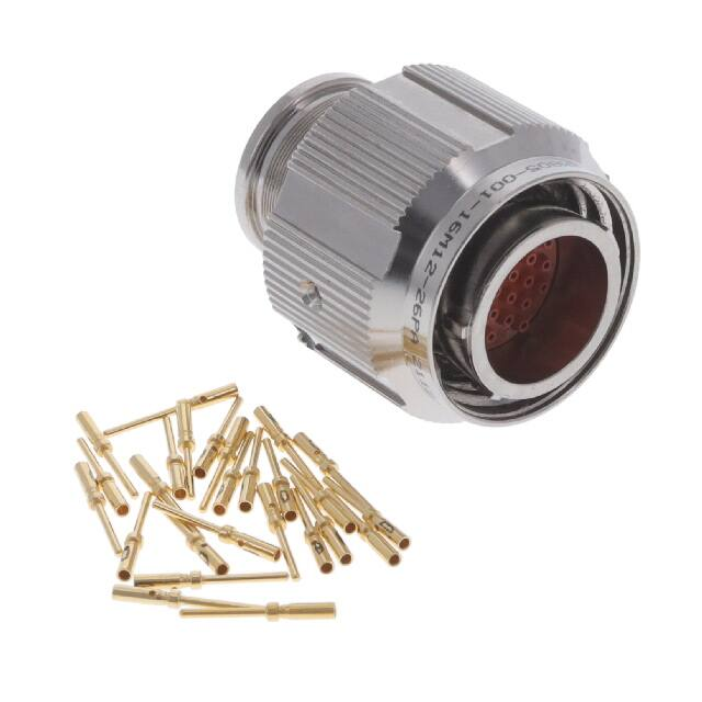


 工商网监
湘ICP备2023018690号
工商网监
湘ICP备2023018690号
