NTC Miniature
Series
Thermometrics
Thermoprobes
Applications
Descriptions
NTC Type P20, P25 and P30
NTC Type P20, P25 and P30
• Miniature bead-in-glass probes feature high
reliability, ease of handling and very fast response
time. The longer body length makes them
particularly well-suited for applications where fast
response and immersion in fluids are the major
requirements.
• The Type P20, P25 and P30 miniature thermprobes
consist of a small bead thermistor hermetically
sealed in the tip of a shock-resistant solid glass rod.
The miniature thermoprobes have improved stability
over glass coated and ruggedized glass bead
thermistors.
NTC Type P60, P65, P85 and P100
NTC Type P60, P65, P85 and P100
• Thermoprobes are recommended for all low cost ,
general purpose applications involving temperature
measurement and control, circuit temperature
compensation, liquid level sensing or fluid flow
sensing. They are ideally suited for applications, that
require a reliable, low cost sensor.
• The Type P60, P65, P85 and P100 thermoprobes
consist of a large bead thermistor hermetically
sealed in the tip of a shock resistant solid glass rod.
They have excellent long-term stability.
Amphenol
Advanced Sensors
�Type P20/25/30 Specifications
NTC Types
P20/25/30
dimensions
Thermal and Electrical Properties
Body
Dimensions:
(All Def initions and Test Methods are Per MIL-PRF-23648)
Thermistor Type:
P20
Standard
Body
Lengths
“L”
P25
.025 in (.64 mm)
P30
Minimum Diameter:
.020 in (.51 mm)
code “AA”
.063 in (1.6 mm)
030 in (.76 mm)
code “A”
.125 in (3.2 mm)
.125 in (3.2 mm)
.125 in (3.2 mm)
code “B”
.250 in (6.3 mm)**
.250 in (6.3 mm)
.250 in (6.3 mm)
Nom. Diameter:
.0011 in (.03 mm)
.002 in (.05 mm)
.003 in (.08 mm)
Minimum Lead Length:
.250 in (6.3 mm)
.250 in (6.3 mm)
.250 in (6.3 mm)
Lead Material:
Platinum Alloy
Platinum Alloy
Platinum Alloy
Nominal
Nominal
Resistance
—
—
Lead-wires:
Material System:
Resistance
Resistance
Code
Letter
R-vs-T
Curve
25/125
Ratio
Range @
77°F (25°C)
Range @
77°F (25°C)
Range @
77°F (25°C)
E
0
5.0
—
—
—
A
1
11.8
300 Ω to 680 Ω
300 Ω to 680 Ω
100 Ω to 300 Ω
A
2
12.5
680 Ω to 1.6 kΩ
680 Ω to 1.6 kΩ
300 Ω to 750 Ω
A
3
14.0
1.6 kΩ to 3.6 kΩ
1.6 kΩ to 3.6 kΩ
750 Ω to 1.5 kΩ
A
4
16.9
3.6 kΩ to 6.8 kΩ
3.6 kΩ to 6.8 kΩ
1.5 kΩ to 3.0 kΩ
A
5
19.8
6.8 kΩ to 27 kΩ
6.8 kΩ to 27 kΩ
.0 kΩ to 6.8 kΩ
A
6
22.1
A
7
22.7
27 kΩ to 75 kΩ
27 kΩ to 75 kΩ
13 kΩ to 18 kΩ
B
8
29.4
75 kΩ to 130 kΩ
75 kΩ to 130 kΩ
18 kΩ to 51 kΩ
B
9
30.8
130 kΩ to 240 kΩ
130 kΩ to 240 kΩ
51 kΩ to 82 kΩ
B
10
32.3
240 kΩ to 360 kΩ
240 kΩ to 360 kΩ
82 kΩ to 150 kΩ
B
11
35.7
360 kΩ to 820 kΩ
360 kΩ to 820 kΩ
150 kΩ to 330 kΩ
B
12
38.1
820 kΩ to 1.3 MΩ
820 kΩ to 1.3 MΩ
330 kΩ to 680 kΩ
B
13
45.0
1.3 MΩ to 3.3 MΩ
1.3 MΩ to 3.3 MΩ
680 kΩ to 1.5 MΩ
B
14
48.1
3.3 MΩ to 6.8 MΩ
3.3 MΩ to 6.8 MΩ
1.5 MΩ to 3.0 MΩ
B
15
56.5
6.8 MΩ to 10 MΩ
6.8 MΩ to 10 MΩ
3.0 MΩ to 6.2 MΩ
D
16
75.6
D
16
Thermal Time Constant:
Dissipation Constant:
Power Rating: (in air)
–
–
—
81.0
—
—
6.8 kΩ to 13 kΩ
6.2 MΩ to 10 MΩ
—
—
Still Air at 77°F (25°C):
1.6 sec
2.0 sec
3.0 sec
Plunge into Water:
18 msec
23 msec
60 msec
Still Air at 77°F (25°C):
.14 mW/°C
.16 mW/°C
.30 mW/°C
Still Water at 77°F (25°C):
.70 mW/°C
.80 mW/°C
1.50 mW/°C
Maximum Power Rating:
.020 Watts
.025 Watts
.035 Watts
100% Max. Power to:
302 (150°C)
302 (150°C)
302 (150°C)
Derated to 0% at:
572°F (300°C)
572°F (300°C)
572°F (300°C)
Resistance vs temperature characterstics: The nominal resistance range for the zero-power resistance at 77°F (25°C) is shown for each miniature bead-in-glass thermoprobe type and each
available material system. Each material system is denoted by an ordering code letter, a referenced curve number and the nominal 77°F/257°F (25°C/125°C) resistance ratio.
2
�Type 60/65/85/100 Specifications
All thermoprobes are aged for extended periods of time. As
such, they exhibit excellent stability for all service temperatures at or below the aging temperature. Thermoprobes that
are manufactured with material system “E” are aged at 221°F
(105°C); those manufactured with a material system having
a 77°F (25°C)/257°F (125°C) ratio of 16.9 or less are aged at
392°F (200°C); and all other material systems are aged at
572°F (300°C). Intermittent operation at temperatures up to
1112°F (600°C) is permissable, however, degraded stability will
result when the aging temperature is exceeded. This appiles
to the NTC Type P20/25/30 also.
NTC Types 60/65/85/100 dimensions
Probe Length Codes
Probe Length Code Letter
Tolerance Code Length in (mm)
Thermal and Electrical Properties
Body Dimensions
A
B
C
D
F
H
K
M
P
R
0.125
(3.17)
0.25
(6.35)
0.375
(9.52)
0.5
(12.7)
0.75
(19.05)
1
(24.4)
1.25
(3.75)
1.5
(38.1)
1.75
(44.45)
2
(50.8)
(All Def initions and Test Methods are Per MIL-PRF-23648)
Thermistor Type:
P60
P65
P85
P100
Maximum Diameter:
.060 in (1.5 mm)
.065 in (1.7 mm)
.085 in (2.2 mm)
.100 in (2.5 mm)
Standard Length Code “B”
.250 in (6.3 mm)
.250 in (6.3 mm)
.250 in (6.3 mm)
.250 in (6.3 mm)
Standard Length Code “D”
.500 in (12.7 mm)
.500 in (12.7 mm)
.500 in (12.7 mm)
.500 in (12.7 mm)
Length Codes Available
“A”, “C”
“A”, “C”
“A”, “C”, “F”, “H”
“A”, “C”, “F”, “H”
(Special Order Only)
“K”, “M”, “P”, “R”
lead-wires:
Nom. Diameter:
.008 in (.20 mm)
.008 in (.20 mm)
.012 in (.30 mm)
.012 in (.30 mm)
Minimum Lead Length:
.875 in (22 mm)
.875 in (22 mm)
.875 in (22 mm)
.875 in (22 mm)
Lead Material:
Tinned Dumet
Tinned Dumet
Tinned Dumet
Tinned Dumet
Material System:
Code
Letter
Nominal
Resistance
25/125 Ratio
R-vs-T
Curve
Nominal
Resistance
Range @ 77°F (25°C)
Nominal
Resistance
Range @ 77°F (25°C)
Nominal
Resistance
Range @ 77°F (25°C)
Nominal
Resistance
Range @ 77°F (25°C)
E
0
5.0
30 to 51 Ω
30 to 51 Ω
30 to 51 Ω
30 to 51 Ω
A
1
11.8
51 to 150 Ω
51 to 150 Ω
51 to 150 Ω
51 to 150 Ω
A
2
12.5
150 to 360 Ω
150 to 360 Ω
150 to 360Ω
150 to 360 Ω
A
3
14.0
360 to 750 Ω
360 to 750 Ω
360 to 750 Ω
360 to 750 Ω
A
4
16.9
750 to 1.5 kΩ
750 to 1.5 kΩ
750 to 1.5 kΩ
750 to 1.5 kΩ
A
5
19.8
1.5 k to 3.6 kΩ
1.5 k to 3.6 kΩ
1.5 k to 3.6 kΩ
1.5 k to 3.6 kΩ
A
6
22.1
3.6 k to 6.2 kΩ
3.6 k to 6.2 kΩ
3.6 k to 6.2 kΩ
3.6 k to 6.2 kΩ
A
7
22.7
6.2 k to 9.1 kΩ
6.2 k to 9.1 kΩ
6.2 k to 9.1 kΩ
6.2 k to 9.1 kΩ
B
8
29.4
9.1 k to 27 kΩ
9.1 k to 27 kΩ
9.1 k to 27 kΩ
9.1 k to 27 kΩ
B
9
30.8
27k to 43 kΩ
27 k to 43 kΩ
27 k to 43 kΩ
27 k to 43 kΩ
B
10
32.3
43 k to 75 kΩ
43 k to 75 kΩ
43 k to 75 kΩ
43 k to 75 kΩ
B
11
35.7
75 k to 160 kΩ
75 k to 160 kΩ
75 k to 160 kΩ
75 k to 160 kΩ
B
12
38.1
160 k to 360 kΩ
160 k to 360 kΩ
160 k to 360 kΩ
160 k to 360 kΩ
B
13
45.0
360 k to 750 kΩ
360 k to 750 kΩ
360 k to 750 kΩ
360 k to 750 kΩ
B
14
48.1
750 k to 1.5 MΩ
750 k to 1.5 MΩ
750 k to 1.5 MΩ
750 k to 1.5 MΩ
B
15
56.5
1.5 M to 3.0 MΩ
1.5 M to 3.0 MΩ
1.5 M to 3.0 MΩ
1.5 M to 3.0 MΩ
D
16
75.6
3.0 M to 8.2 MΩ
3.0 M to 8.2 MΩ
3.0 M to 8.2 MΩ
3.0 M to 8.2 MΩ
D
16
81.0
8.2 M to 20 MΩ
8.2 M to 20 MΩ
8.2 M to 20 MΩ
8.2 M to 20 MΩ
Thermal Time Constant:
Still Air at 77°F (25°C):
12 sec
13 sec
16 sec
22 sec
Plunge into Water:
300 msec
320 msec
400 msec
600 msec
Dissipation Constant:
Still Air at 77°F (25°C):
.60 mW/°C
.65 mW/°C
.85 mW/°C
1.00 mW/°C
Still Water at 77°F (25°C):
3.00 mW/°C
3.30 mW/°C
4.00 mW/°C
5.00 mW/°C
Power Rating: (in air)
Maximum Power Rating:
.060 Watts
.065 Watts
.085 Watts
.100 Watts
100% Max Power to:
392°F (200°C)
392°F (200°C)
392°F (200°C)
392(200°C)
Derated to 0% at:
572°F (300°C)
572°F (300°C)
572°F (300°C)
572(300°C)
Resistance vs temperature characterstics: The nominal resistance range for the zero-power resistance at 77°F (25°C) is shown for each miniature bead-in-glass thermoprobe type and each
available material system. Each material system is denoted by an ordering code letter, a referenced curve number and the nominal 77°F/257°F (25°C/125°C) resistance ratio.
3
�Ordering Information
Type P20/25/30
Type P60/65/85/100
The code number to be ordered may be specif ied as follows:
P
Miniature bead-in-glass thermoprobe structure
Code
Maximum Probe Diameter
20
20 mil
25
25 mil
30
30 mil
Code
Probe Length
AA
0.063 in (1 mm) ±0.015 in (±0.381 mm)
A
0.125 in (3 mm) ±0.032 in (±0.81 mm)
B
0.25 in (6 mm) ±0.05 in (±1 mm)
Code
Material System Code
X
See thermal and electrical properties table
Code Zero-Power
103
Resistance at 77°F (25°C)**
Code
Toleranc Code Letter
F ±1%
G ±2%
J ±5%
K ±10%
L ±15%
M ±20%
N ±25%
P
±30%
Q ±40%
R ±50%
S
Non standard consult
Thermometrics
The code number to be ordered may be specif ied as follows:
P
Miniature bead-in-glass thermoprobe structure
Code
Maximum Probe Diameter
60
60 mil
65
65 mil
85
80 mil
100
100 mil
Code
Probe Length (see probe length codes table for restrictions)
B
0.25 in (6 mm) ±0.05 in (±1 mm)
D
0.5 in (12 mm) ±0.063 in (±1 mm)
Code
Material System Code
X
See thermal and electrical properties table
Code Zero-Power
104
Resistance at 77°F (25°C)**
Code
Toleranc Code Letter
F ±1%
G ±2%
J ±5%
K ±10%
L ±15%
M ±20%
N ±25%
P
±30%
Q ±40%
R ±50%
S
Non standard consult
Thermometrics
P -
P -
____
-
____ - ____
-
____
-
____ Typical model number
____
- ____ - ____
-
____ -
____ Typical model number
*Special tolerances are available on request. Consult Thermometrics for special resistance tolerances, non-standard resistances and/or non-standard temperatures.
*Special tolerances are available on request. Consult Thermometrics for special resistance tolerances, non-standard resistances and/or non-standard temperatures.
**The zero-power resistance 77°F (25°C), expressed in Ω, is identified by a three digit code number.
The first two digits represent significant figures, and the last digit specifies the number of zeros to
follow. Example: 10 kΩ = 103.
**The zero-power resistance 77°F (25°C), expressed in Ω, is identified by a three digit code number.
The first two digits represent significant figures, and the last digit specifies the number of zeros to
follow. Example: 100 kΩ = 104.
The standard resistance values are from the 24-value series decade as specified in Military
The standard resistance values are from the 24-value series decade as specified in Military
Standards MS90178.
Standards MS90178.
1.0/1.1/1.3/1.5/1.6/1.8/2.0/2.2/2.4/2.7/3.0
1.0/1.1/1.3/1.5/1.6/1.8/2.0/2.2/2.4/2.7/3.0
3.3/3.6/3.9/4.3/4.7/5.1/5.6/6.2/6.8/7.5/8.2/9.1
3.3/3.6/3.9/4.3/4.7/5.1/5.6/6.2/6.8/7.5/8.2/9.1
Amphenol
Advanced Sensors
www.amphenol-sensors.com
© 2014 Amphenol Corporation. All Rights Reserved. Specifications are subject to change without notice.
Other company names and product names used in this document are the registered trademarks or
trademarks of their respective owners.
AAS-920-327A-04/2014
�
很抱歉,暂时无法提供与“P100BB105M”相匹配的价格&库存,您可以联系我们找货
免费人工找货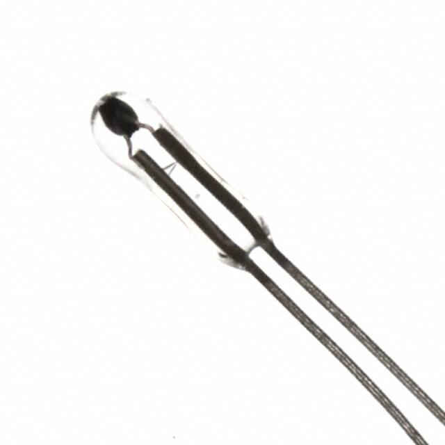


 工商网监
湘ICP备2023018690号
工商网监
湘ICP备2023018690号
