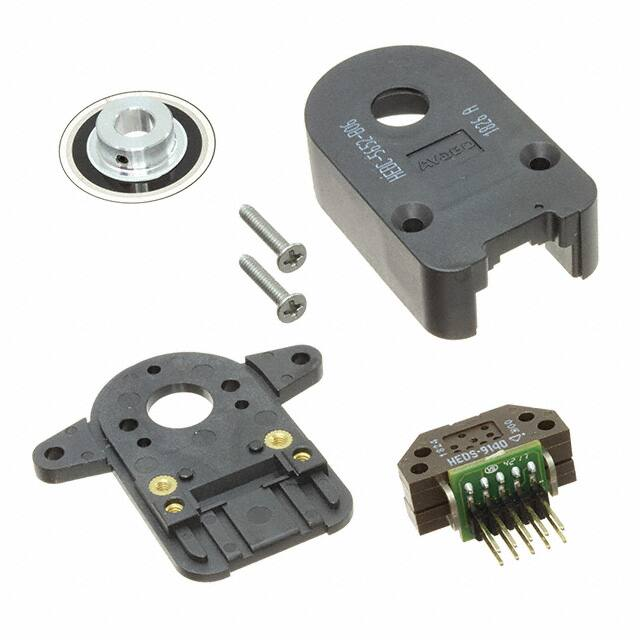
HEDC-55xx/HEDC-56xx
Two or Three Channel Quick Assembly Encoders
With Connector Latch
Data Sheet
Description
Features
The HEDC-5xxx-xxx, while similar to the industry standard
HEDS-5xxx kit encoder, provides a connector latch on
the cover housing to improve connector retention. This
device is built upon the HP/Agilent/Avago HEDS-9000
series encoder module, and provides the same performance, low cost, high reliability, high resolution, and ease
of assembly customers have come to expect.
• Available in two or three channel encoder A, B and I
Each encoder contains a lensed LED source, an integrated
circuit with detectors and output circuitry. A codewheel
(disk) which rotates between the emitter and detector IC
generates two square waves in quadrature. Three channel
units include an index pulse (high state) of 90°e, which is
generated once for each full rotation.
• Quick assembly
HEDC-5xxx-xxx provides resolutions from 50 to 1024 CPR,
and accommodating shaft diameters from 2 mm to 8 mm.
This kit encoder may be quickly and easily mounted to
a motor. The electrical interface is through five (single
ended) or ten (differential versions) 0.025 inch square
pins on 0.100 centers. Interface cable assemblies to meet
customer requirements are available also.
The differential (line driver) version offers enhanced performance when the encoder is used in noisy environments, or when it is required to drive long cables. It uses
an industry standard RS422 compatible line driver IC, AEIC
7272, which provides differential outputs for each of the
encoder channels. Suggested line receivers are 26LS32
and 26LS33.
• Latching connector design
• Single 5 V supply
• Resolution of up to 1024 CPR
• TTL compatible, with single ended or differential
output.
• No signal adjustment required
• Small size -40° C to 100° C operating temperature
Applications
High volume applications such as printers, plotters, tape
drives, textile machines, positioning tables and also
automatic handlers among others.
Note: Avago Technologies encoders are not recommended for use in
safety critical applications, e.g., ABS braking systems, power steering, life
support systems and critical care medical equipment. Avago’s products
and software are not specifically designed, manufactured or authorized
for sale as parts, components or assemblies for the planning, construction, maintenance or direct operation of a nuclear facility or for use in
medical devices or applications. Customers are solely responsible, and
waive all rights to make claims against Avago or its suppliers, for all
losses, damage, expense or liability in connection with such use. Please
contact your local sales representative if more clarification is needed.
�Package Dimensions - HEDC-55xx / HEDC-56xx Single ended output:
Standard mounting considerations
16.59
3X n1.98
Equally spaced on n20.90
47.14
15.53
Thru hole option:
n9.1
31.05
19.05
n11.13 (Thru)
2X n2.87
v n13.91
x1.14
1.3
PIN 1 MARK
13.18
Single ended output with standard mounting base plate
External ear mounting considerations
53.71
46.02
16.59
Thru hole option:
n9.1
3.43
3X n1.98
Equally spaced on n20.90
31.05
n11.13 (Thru)
19.05
47.14
15.53
2X n2.87
1.3
PIN 1 MARK
2X n2.87
v n13.91
x1.14
13.18
Single ended output with external ear mounting base plate
Package Dimensions
47.14
single
ended
differential/
line driver
unit
width
31.05
31.05
mm
height
16.59
16.59
mm
length
47.14
51.76
mm
31.05
16.59
A latching connector design is used on both versions.
Single Ended Output Signals
Note: All dimensions are in millimeters
2
51.76
31.05
�Package Dimensions - HEDC-55xx / HEDC-56xx Differential output:
Standard mounting considerations
31.05
16.59
n11.13 (Thru)
19.05
3X n1.98
Equally spaced on n20.90
15.53
THRU HOLE OPTION:
n9.1
51.76
2X n2.87
v n13.91
x1.13
0.65
PIN 1 MARK
17.13
Differential output with standard mounting base plate
External ear mounting considerations
16.59
3.43
53.71
46.02
31.05
n11.13 (Thru)
THRU HOLE OPTION:
n9.1
3X n1.98
31.05
Equally spaced
on n20.90
19.05
15.53
47.14
51.76
16.59
2X n2.87
2X n2.87
v n13.91
x1.13
0.65
PIN 1 MARK
Single Ended Output Signals
17.13
Note: All dimensions are in millimeters
Differential output with external ear mounting base plate
Package Dimensions
single
ended
differential/
line driver
unit
width
31.05
31.05
mm
height
16.59
16.59
mm
length
47.14
51.76
mm
51.76
16.59
A latching connector design is used on both versions.
Differential Output Signals
Note: All dimensions are in millimeters
3
31.05
�Theory of Operation
Definitions (see phase diagram)
This encoder translates rotary motion of a shaft into a two
or three-channel digital output.
Count (N): The number of bar and window pairs or counts
As shown in the block diagram, these encoders contain
a single Light Emitting Diode (LED) as its light source.
The light is collimated into a parallel beam by means of
a single polycarbonate lens located directly over the LED.
Opposite the emitter is the integrated detector circuit.
This IC consists of multiple sets of photodetectors and
the signal processing circuitry necessary to produce the
digital waveforms.
One Cycle (C): 360 electrical degrees (°e), 1 bar and window
The codewheel rotates between the emitter and detector,
causing the light beam to be interrupted by the pattern of
spaces and bars on the codewheel. The photodiodes which
detect these interruptions are arranged in a pattern that
corresponds to the radius and design of the codewheel.
The photodiode outputs are then fed through the signal
processing circuitry resulting in A, A-Bar, B and B-Bar
(also I and I-Bar for 3-channel units). Comparators receive
these signals and produce the final outputs for channels
A and B. Due to this integrated phasing technique, the
digital output of channel A is in quadrature with that of
channel B (90 degrees out of phase).
The output of the comparator for I and I-Bar is sent to
the index processing circuitry along with the outputs of
channels A and B.
per revolution (CPR) of the codewheel.
pair.
One Shaft Rotation: 360 mechanical degrees, N cycles.
Position Error (∆Θ): The normalized angular difference
between the actual shaft position and the position
indicated by the encoder cycle count.
Cycle Error (∆C): An indication of cycle uniformity. The dif-
ference between an observed shaft angle which gives rise
to one electrical cycle, and the nominal angular increment
of 1/N of a revolution.
Pulse Width (P): The number of electrical degrees that an
output is high during 1 cycle. This value is nominally 180°e
or ½ cycle.
Pulse Width Error (∆P): The deviation, in electrical degrees,
of the pulse width from its ideal value of 180°e.
State Width (S): The number of electrical degrees between
a transition in the output of channel A and the neighbouring transition in the output of channel B. There are 4 states
per cycle, each nominally 90°e.
State Width Error (∆S): The deviation, in electrical degrees,
The final output of channel I is an index pulse PO which
is generated once for each full rotation of the codewheel.
This output PO is a one state width (nominally 90 electrical degrees), high state true pulse which is coincident with
the low states of channels A and B.
of each state width from its ideal value of 90°e.
Block Diagram
Phase Error (∆φ): The deviation of the phase from its ideal
RESISTOR
V CC
PHOTODIODES
LENS
COMPARATORS
A
+
4
CHANNEL A
A B
LED
+
3
CHANNEL B
B I
+
I SIGNAL
PROCESSING
CIRCUITRY
5
CHANNEL I
2
INDEX
PROCESSING
CIRCUITRY
GND
1
EMITTER SECTION
4
CODE
WHEEL
DETECTOR SECTION
Phase (φ): The number of electrical degrees between the
center of the high state of channel A and the center of the
high state of channel B. This value is nominally 90°e for
quadrature output
value of 90°e.
Index Pulse Width (PO): The number of electrical degrees
that an index output is high during one full shaft rotation.
This value is nominally 90°e or ¼ cycle.
�Absolute Maximum Ratings
Parameter
Storage Temperature, TS
-40° C to 100° C
Operating Temperature, TA
-40° C to 100° C
Supply Voltage, VCC
-0.5 V to 7 V
Output Voltage, VO
-0.5 V to VCC
Output Current per Channel, IOUT (Single ended)
-1.0 mA to 5 mA
Vibration
20 g, 5 to 1000 Hz
Shaft Axial Play
± 0.25 mm
(± 0.010 in)
Shaft Eccentricity Plus Radial Play
0.1 mm
(0.004 in)
Velocity
30,000 RPM
Acceleration
250,000 rad/sec2
Direction of Rotation: When the codewheel rotates in the clockwise direction (as viewed from the encoder end of the
motor), channel A will lead channel B. If the codewheel rotates in the counter-clockwise direction, channel B will lead
channel A.
Index Pulse Width (PO): The number of electrical degrees that an index output is high during one full shaft rotation. This
value is nominally 90°e or ¼ cycle.
Output Waveform Phase Diagram
Clockwise Rotation – A leads B
C
P
2.4 V
0.4 V
Amplitude
φ
S1
S2
S3
S4
2.4 V
0.4 V
t2
t1
2.4 V
0.4 V
P0
Rotation of Code Wheel counter clockwise, viewed from the top of encoder
5
CH. A
CH. B
CH. I
�Recommended Operating Conditions
Parameter
Sym.
Min.
Temperature
TA
-40
Supply Voltage
VCC
4.5
Load Capacitance
Count Frequency
Typ.
Max.
Units
100
°C
5.5
Volts
Ripple < 100 mVp-p
CL
100
pF
2.7 kΩ pull-up
f
100
kHz
Velocity (rpm) x N/60
5.0
Notes
Electrical Characteristics
Electrical Characteristics over Recommended Operating Range.
Part No.
Parameter
Sym
2 channel
Supply Current
High Level Output Voltage
Low Level Output Voltage
ICC
VOH
VOL
Rise Time
Fall Time
tr
tf
Supply Current
High Level Output Voltage
Low Level Output Voltage
ICC
VOH
VOL
Rise Time
Fall Time
tr
tf
Rise/Fall time
tr
tf
3 channel
Line Driver
Min
2.4
Typ.*
Max.
Units
Notes
17
40
mA
V
V
IOH = -40 μA max
IOL = 3.2 mA
ns
ns
CL = 25 pF
RL = 11 kΩ pull-up
mA
V
V
IOH = -200 μA max
IOL = 3.86 mA
180
40
ns
ns
CL = 25 pF
RL = 2.7 kΩ pull-up
120**
ns
CL = 40 pF
RL = 100 Ω
0.4
200
50
30
2.4
57
85
0.4
* Typical values specified at VCC = 5.0 V and 25° C and for single ended, unless otherwise stated.
** Applicable for line driver output version.
Mechanical Characteristics
Parameter
Symbol
Codewheels Fit These Shaft
Diameters
Moment of Inertia
J
Required Shaft Length
Bolt Circle[3]
Mounting Screw Size
Dimension
Tolerance
Units
2, 3, 4, 5, 6, 8
+0.000
-0.015
mm
5/32, 1/8, 3/16, 1/4
+0.0000
-0.0007
in
0.6 (8.0 x 10⁻⁶)
g-cm2 (oz-in-s2)
14.0 (0.55)
± 0.5
(± 0.02)
mm (in.)
2 screw mounting
19.05
(0.750)
± 0.13
(± 0.005)
mm (in.)
3 screw mounting
20.90
(0.823)
± 0.13
(± 0.005)
mm (in.)
external mounting ears
46.0
(1.811)
± 0.13
(± 0.005)
mm (in.)
2 screw mounting
M 2.5 or (2-56)
mm (in.)
3 screw mounting
M 1.6 or (0-80)
mm (in.)
external mounting ears
M 2.5 or (2-56)
mm (in.)
Encoder Base Plate Thickness
0.33 (0.130)
mm (in.)
Hub Set Screw
(2-56)
(in.)
Notes
1. An optional cover provides an 8.9 mm (0.35 inch) diameter hole through the housing for longer motor shaft.
2. Encoder must be aligned as shown in the “Encoder Mounting and Assembly” instructions.
3. The recommended mounting screw torque for 2 screw mounting is 1.0 kg-cm (0.88 in-lbs). The recommended mounting screw torque for 3 screw
mounting is 0.50 kg-cm (0.43 in-lbs).
6
�Encoding Characteristics
Encoding characteristics are applicable per the Recommended Operating Conditions, unless otherwise specified. Values
are for the worst case error over the full rotation.
Description
Sym.
Two Channel
Pulse Width Error
Logic State Width Error
Phase Error
Position Error
Cycle Error
Three Channel
Pulse Width Error
Logic State Width Error
Phase Error
Position Error
Cycle Error
Index Pulse Width
Min.
Typ.*
Max.
Units
∆P
∆S
∆Φ
∆Θ
∆C
7
5
2
10
3
45
45
20
40
5.5
°e
°e
°e
min. of arc
°e
∆P
∆S
∆Φ
∆Θ
∆C
PO
45
35
15
40
5.5
125
°e
°e
°e
min. of arc
°e
°e
55
5
5
2
10
3
90
CH.I rise after CH.A or
CH. B fall
-40° C to +100° C
t1
-300
100
250
ns
CH.I fall after CH.A or
CH. B rise
-40° C to +100° C
t2
70
150
1000
ns
Electrical Interface
To ensure reliable encoding performance, the three
channel single ended encoders require 2.7 kΩ (±10%)
pull-up resistors on output pins 2, 3 and 5 (Channels A, B
and I) as shown in Figure 1. These pull-up resistors should
be located as close to the encoder as possible (within 4
feet). Each of the outputs can drive a single TTL load in this
configuration. The two channel version does not normally
require pull-up resistors. However, 3.2 kΩ pull-up resistor
on output pins 3 and 5 (Channel A and B) are recommended
to improve rise times, especially when operating above
100 KHz frequencies.
R = 2.7 kΩ
+5V
R
5
VCC
1
Figure 1. Pull-up resistors on 3 Channel encoder output
7
GND
For the line driver option, differential loading of 100 Ω and
40 pf (RS422 configuration), yields rise and fall times of
120 ns typical, with approximately 60 ns of skew. Driving
moderate to long lengths of cable un-terminated reduces
power consumption and can reduce skew to < 10 ns.
R
R
CH. B
CH. A
CH. I
TO OUTPUT LOGIC
(ONE TTL PER OUTPUT)
�Pin out descriptions
Pin 1
Pin 1
Pin 2
Pin 5
5 Pin (Single Ended) Version
10 Pin (Differential Line Driver) Version
Pin #
Description
Pin #
1
Ground
Description
Standard
Description
HP/Agilent Option
2
CH I (*)
1
Ground
No connection
3
CH A
2
Ground
+ 5 VDC
4
+ 5 VDC
3
Ch I- (*)
Ground
CH B
4
Ch I+ (*)
No connection
5
Ch A-
CH A –
6
Ch A+
CH A +
7
+5VDC
CH B –
8
+5VDC
CH B +
9
CH B-
CH I – (*)
10
CH B+
CH I + (*)
5
(*) – Applicable to 3 channel units only
Standard Cable options
Cable Description (All include one end terminated with the mating latching connector,
and the other end has flying leads.)
Part Number
Shielded Cable Length
5 conductor, unshielded 22 ga (for single ended use)
HEDC-8520-0060
600 mm
8 conductor, shielded, 24 ga (for line driver use) – Standard option
HEDC-8850-0060
600 mm
8 conductor, shielded, 24 ga (for line driver use) – HP/Agilent/Avago option
HEDC-8851-0060
600 mm
For other cable options or customization request, please contact your Avago representative or distributor.
8
�Connector (HEDC-8520-0060)
Twisted & tinned pig tail
5 ±1.00
Front1
70 ±3.00
∅5.00 ±0.50
25 ±2.00
600 ±30.00
Pin 1:
Pin 2:
Pin 3:
Pin 4:
Pin 5:
Color:
Color:
Color:
Color:
Color:
Black (GND)
Green (I)
White (A)
Red (+5VDC)
Brown (B)
Right1
Connector (HEDC-88xx-0060)
Twisted & tinned pig tail
5 ±1.00
∅7.00 ±0.50
70 ±3.00
25 ±2.00
Front1
600 ±30.00
Standard connector pin out (HEDC-8850-0060)
Color: White/Brown Stripe (B-)
Color: White/Green Stripe (+5VDO)
White/Blue Stripe
(A-)
White/Orange Stripe
(I-)
Not connected
Pin 10:
Pin 8:
Pin 6:
Pin 4:
Pin 2:
Pin 9:
Pin 7:
Pin 5:
Pin 3:
Pin 1:
Color: Brown/White Stripe
Not connected
Color: Blue/White Stripe
Color: Orange/White Stripe
Color: Green/White Stripe
(B+)
(A+)
(I+)
(GND)
Right1
HP/Agilent/Avago connector pin out (HEDC-8851-0060)
Color: White/Brown Stripe
Color: White/Green Stripe
White/Blue Stripe
White/Orange Stripe
Not connected
(I-)
(B-)
(A-)
(GND)
Pin 9:
Pin 7:
Pin 5:
Pin 3:
Pin 1:
Pin 10:
Pin 8:
Pin 6:
Pin 4:
Pin 2:
Right1
9
(I+)
Color: Brown/White Stripe
(B+)
Color: Green/White Stripe
(A+)
Color: Blue/White Stripe
Not connected
Color: Orange/White Stripe (+5VDC)
�Ordering Information
H
E
D
C
−
5
5
2
0
−
0
E
1
Through Hole
0 None
1 Cover Extension
2 Hole in Cover
Output
2 2 Channel − Voltage (*)
3 2 Channel − Differential (*)
5 3 Channel − Differential (AVAGO)
6 3 Channel − Voltage (*)
7 3 Channel − Differential (*)
Mounting Type
5 Standard
6 External Mounting Ear
Avago
Part Number
Cross – Reference
US Digital E5 Part Number
HEDC-5520 - B03
HEDC-5520 - B04
HEDC-5520 - H03
HEDC-5520 - H14
HEDC-5522 - H14
HEDC-5520 - A06
HEDC-5520 - J14
HEDC-5520 - B14
HEDC-5520 - B13
HEDC-5560 - B14
HEDC-5562 - E06
HEDC-5560 - B14
HEDC-5660 - B13
HEDC-5560 - E14
HEDC-5652 - H06
HEDC-5652 - H16
HEDC-5652 - B06
HEDC-5550 - H14
HEDC-5552 - H14
HEDC-5570 - B03
HEDC-5570 - B14
HEDC-5570 - A14
HEDC-5670 - B12
E5-1000-125-N-S-D-D
E5-1000-156-N-S-D-D
E5-400-125-N-S-D-D
E5-400-197-N-S-D-D
E5-400-197-N-S-H-D
E5-500-250-N-S-D-D
E5-1024-197-N-S-D-D
E5-1000-197-N-S-D-D
E5-1000-315-N-S-D-D
E5-1000-197-I-S-D-D
E5-200-250-I-S-H-D
E5-1000-197-I-S-D-D
E5-1000-315-I-S-D-G
E5-200-197-I-S-D-D
E5-400-250-I-L-H-G
E5-400-313-I-L-H-G
E5-1000-250-I-L-H-G
E5-400-197-I-L-D-D
E5-400-197-I-L-H-D
E5-1000-125-I-D-D-D
E5-1000-197-I-D-D-D
E5-1000-500-I-D-D-D
E5-1000-236-I-D-D-D
Resolution CPR
S 50
K 96
C 100
D 192
E 200
F 256
G 360
H 400
A 500
I 512
B 1000
J 1024
Shaft Diameter
01 2 mm
02 3 mm
03 1/8 in
04 5/32 in
05 3/16 in
06 1/4 in
11 4 mm
14 5 mm
12 6 mm
13 8 mm
16 5/16 in
Mounting
Channels
Pinout
Option
Through
hole
cpr
Shaft ∅
Standard
Standard
Standard
Standard
Standard
Standard
Standard
Standard
Standard
Standard
Standard
Standard
External Ear
Standard
External Ear
External Ear
External Ear
Standard
Standard
Standard
Standard
Standard
External Ear
Two
Two
Two
Two
Two
Two
Two
Two
Two
Three
Three
Three
Three
Three
Three
Three
Three
Three
Three
Three
Three
Three
Three
Standard
Standard
Standard
Standard
Standard
Standard
Standard
Standard
Standard
Standard
Standard
Standard
Standard
Standard
Avago
Avago
Avago
Avago
Avago
Standard
Standard
Standard
Standard
single ended
single ended
single ended
single ended
single ended
single ended
single ended
single ended
single ended
single ended
single ended
single ended
single ended
single ended
differential
differential
differential
differential
differential
differential
differential
differential
differential
none
none
none
none
cover
none
none
none
none
none
cover
none
none
none
cover
cover
cover
none
cover
none
none
none
none
1000cpr
1000cpr
400cpr
400cpr
400cpr
500cpr
1024cpr
1000cpr
1000cpr
1000cpr
200cpr
1000cpr
1000cpr
200cpr
400cpr
400cpr
1000cpr
400cpr
400cpr
1000cpr
1000cpr
500cpr
1000cpr
1/8 inch
5/32 inch
1/8 inch
5mm
5mm
1/4 inch
5mm
5mm
8mm
5mm
¼ inch
5mm
8mm
5mm
1/4 inch
5/16 inch
1/4 inch
5mm
5mm
1/8 inch
5mm
5mm
6mm
For other options or customization requests, please contact your Avago representative or distributor.
Disclaimer: All the above information is preliminary and subjected to change. Please contact factory for further information.
For product information and a complete list of distributors, please go to our web site:
www.avagotech.com
Avago, Avago Technologies, and the A logo are trademarks of Avago Technologies in the United States and other countries.
Data subject to change. Copyright © 2005-2013 Avago Technologies. All rights reserved.
AV02-3381EN - November 21, 2013
�


 工商网监
湘ICP备2023018690号
工商网监
湘ICP备2023018690号
