AP8802HEV2 USER GUIDE
DESCRIPTION
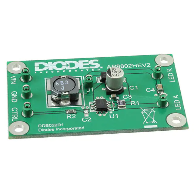
The AP8802HEV2, Figure 1, is a PCB constructed using an FR4 base for evaluating the AP8802H
LED driver with internal switch in the SOP-8L-EP package. The evaluation board can be used to drive
an external choice of LEDs; the total forward voltage across the LEDs depending on the number and
type connected. [1]
The suggested operating voltage for the evaluation board ranges from 8V to 60V maximum.
Higher voltage means lower supply current.
The nominal current for the evaluation board is set at 1A with a 0R2 sense resistor, R1.
Test point CTRL provides a connection point for DC or PWM dimming and shutdown.
Note: The evaluation board does not have reverse polarity protection
Warning: with 1A output, the connected LEDs will be hot and very bright
+
V
1-16 LEDs
_
8 - 60V DC
Figure 1: AP8802HEV2 evaluation board and connection diagram
Issue 1 – August 2010
© Diodes Incorporated, 2010
www.diodes.com
�AP8802HEV2
AP8802H DEVICE DESCRIPTION
The AP8802H s a step-down DC/DC converter designed to drive LEDs with a constant current. The
device can drive up to seventeen LEDs, in series, depending largely on their forward voltage, from a
source of between 8V and 60V. Series connection of the LEDs provides identical LED currents,
resulting in uniform brightness and eliminates the need for ballast resistors. The AP8802H switches at
frequencies up to 500KHz. This allows the use of small size external components, hence minimizing
the PCB area needed.
The maximum output current of the AP8802H is set via an external resistor connected between the
VIN and SET input pins. Dimming is achieved by applying either a DC voltage or a PWM signal at the
CTRL input pin. An input voltage of 0.2V or lower at CTRL shuts down the output at SW and puts the
device into a low-current standby state.
The device includes the output switch and a current sense circuit, which requires an external sense
resistor to set the nominal current up to 1A.
AP8802H DEVICE FEATURES
•
•
•
•
•
•
•
•
•
DEVICE APPLICATIONS
•
•
•
•
LED driving current up to 1A
Input voltage from 8V to 60V
High efficiency up to 92%
High switching frequency up to 500KHz
minimum
PWM/DC input for dimming control
Built-in soft-start function
Built-in output open-circuit protection
SOP-8L, in environmentally “Green” Molding
Compound (No Br, Sb)
Lead Free Finish/RoHS Compliant
Commercial & industrial lighting
Small LCD panel backlighting
Appliance interior lighting
Architecture detail lighting
( Top View )
SET 1
GND
NC
2
AP8802H
3
VIN 4
8
CTRL
7
GND
6
5
SW
SW
SOP-8L-EP
ORDERING INFORMATION
EVALBOARD ORDER
NUMBER
AP8802HEV2
DEVICE ORDER NUMBER
Package
Tape &
Reel
AP8802H
SP (SOP-8L-EP)
-13
Device
Please note: Evaluation boards are subject
to availability and qualified leads.
Issue 1 – August 2010
www.diodes.com
© Diodes Incorporated, 2010
2
�AP8802HEV2
AP8802HEV2 EVALUATION BOARD
REFERENCE DESIGN
The AP8802HEV2 is an evaluation board configured to be used with the AP8802H in SOP-8L-EP
package. The target application is a driver for one or more series-connected LEDs for luminaires in
both commercial and automotive applications.
The maximum operating voltage for the evaluation board is 60V, and a 0R2 sense resistor R1 sets the
nominal current at 1A.
An accurate way of determining the current, avoiding the need to insert an ammeter in the current
path, is to measure the voltage on the sense resistor. A 10k resistor and a 1uF capacitor can be used
to form a low pass filter and the voltage across the capacitor represents a more stable DC reading of
current. Using this method, 200mV represents 1 Amp when using a 0R2 sense resistor.
The CTRL pin connects to a low pass filter within the AP8802H chip to provide some decoupling, but
the external capacitor C2 (100nF) can be used to provide additional decoupling to reduce any high
frequency noise as well as providing the soft start function.
Name
SW
GND
SET
CTRL
VIN
NC
Description
Switch Pin. Connect inductor/freewheeling diode here. Minimize trace area at this pin to reduce
EMI.
GND pin
Set Nominal Output Current Pin. Configure the output current of the device.
Dimming and On/Off Control Input. Input voltage of 0.2V or lower forces the device into low
current standby mode and shut off the output. A PWM signal allows the output current to be
adjusted above or below the level set by the resistor connected to SET input pin.
The input impedance is about 50k, and if the pin is left open VCTRL = VREF
Input Supply Pin. Must be locally bypassed with a capacitor.
No connection
Both DC and PWM dimming can be achieved by driving the CTRL pin. For DC dimming, the CTRL pin
may be driven between 0.3V and 1.25V. Driving the CTRL pin below 0.2V will shut down the output
current. For PWM dimming, an external open-collector NPN transistor or open-drain N-channel
MOSFET can be used to drive the CTRL pin. The PWM frequency can be around 100Hz to 1 kHz.
For better resolution, PWM capacitor C2 should be removed from the evaluation board, to give a more
accurate duty cycle.
Shorting R2 will connect the test pin CTRL to device pin CTRL if needed. The external capacitor C2
on the CTRL pin sets the soft start time. The amount of soft start time achievable is approximately
0.2ms/nF.
For other reference designs or further applications information, please refer to the AP8802H
datasheet.
Issue 1 – August 2010
www.diodes.com
© Diodes Incorporated, 2010
3
�AP8802HEV2
VIN
8V ~ 60V DC
VIN
CTRL
R1
R2
SET
C1
C3
GND
AP8802H
D1
C4
1
C2
L1
GND
SW
Figure 2: Schematic of the Evaluation Board
AP8802H OPERATION
In normal operation, when voltage is applied at VIN, the AP8802Hs internal NDMOS switch is turned
on. Current starts to flow through sense resistor R1, inductor L1, and the LED(s). The current ramps
up linearly, the rate being determined by the input voltage VIN and inductor L1. This rising current
produces a voltage ramp across R1. The internal circuit of the AP8802H senses this voltage and
applies a proportional voltage to the input of the internal comparator. When this voltage reaches an
internally set upper threshold, the NDMOS switch is turned off. The inductor current continues to flow
through R1, L1, the LED(s), Schottky diode D1, and back to the supply rail. The current decays, with
the rate of decay determined by the forward voltage drop of the LEDs and the Schottky diode. This
decaying current produces a falling voltage at R1 which is sensed by the AP8802H. A voltage
proportional to the sense voltage across R1 is applied at the input of the internal comparator. When
this voltage falls to the internally set lower threshold, the NDMOS switch is turned on again. This
switch-on-and-off cycle continues to provide an average current (set by the sense resistor R1) to the
LEDs. Please refer to the datasheet for the threshold limits, AP8802H internal circuits, electrical
characteristics and parameters.
AP8802HEV2 EVALUATION BOARD - BILL OF MATERIALS
Ref
U1
D1
R1
R2
C1
Value
AP8802H
100V, 2A
0R2
0R0
10uF 100V
Package
SOP8LEP
SMB
1210
0805
C2
C3
100nF,100V
0805
C4
100nF 100V
1206
L1
68uH
-
Part Number
AP8802HSPG
B2100
Generic
Generic
generic
NACE100M100V6.3x8
Not Fitted
Generic
NMC0805X7R104K100
Generic
NMC1206X7R104K100
MSS1038-683ML
NPIS104F680MTRF
NPIS24H680MTRF
Manufacturer
DIODES inc
DIODES inc
NIC
Components
NIC
Components
NIC
Components
Coilcraft
NIC Comps.
NIC Comps.
Notes
DC-DC converter
Schottky diode
+/-1%, +/-100ppm
6.3mm x 8mm SMD
electrolytic 85C
X7R +/-20%
X7R +/-20%
68uH, ~0.2R, ~1.5A
Note: if not available, components shown above may be changed without notice.
The FR4 PCB design, with adequate copper top and bottom and plated through vias for thermal
coupling, guarantees a good thermal dissipation for the AP8802H device. Other sources of heat are
the Schottky diode, the inductor and the sense resistor, therefore care must be taken in their
placement.
Issue 1 – August 2010
www.diodes.com
© Diodes Incorporated, 2010
4
�AP8802HEV2
Warning: At 60V operation with 1A output, the board will become hot !
Figure 3: Component layout and circuit board view
AP8802HEV2 Connection Point Definition
Name
Description
VIN
Positive supply voltage.
GND
Supply Ground (0V).
CTRL
LED A
LED K
Internal voltage ref. pin (1.25V). This pin can be used to achieve dimming and
soft-start, and for switching the output current off.
• Leave floating for normal operation.
• See 'Circuit Features' section to achieve dimming, soft-start and for
switching the output current off.
C4
LED A connects to the external LED anode
LED K connects to the external LED cathode
AP8802HEV2 BASIC OPERATION AT FULL VOLTAGE
1. Connect external LEDs across the test pins ‘LED A’ (anode) and ‘LED K’ (cathode). The
number of external LEDs that can be connected depends on their operating power and
forward voltage drop, but typically 16 x 3.2V LEDs can be connected using a 60V rail. For an
external load other than LEDs, the positive terminal of the load should be connected to the
anode and the negative to the cathode.
2. Connect VIN and GND.
Warning: The board does not have reverse battery/supply protection.
3. Set the PSU to the desired input voltage (60V max.)
4. Turn on the PSU. The external LEDs will illuminate and the current should be
approximately 1A
5. The switching waveform on the SW pin can be acquired using the test point J1
Warning: Do not stare at the LEDs directly.
Issue 1 – August 2010
www.diodes.com
© Diodes Incorporated, 2010
5
�AP8802HEV2
CIRCUIT FEATURES
N.B. Remove power whilst changing components!
Soft-start
1.
The AP8802H has a in-built soft start function. A capacitor, C2 may be fitted to the evaluation
board to increase the soft start time by slowing the rise time of the adjust pin at start-up at the
rate of 0.2ms/nF. The board is supplied with a zero-ohm resistor in position R2. Please see
the data sheet for further details.
PWM
1. Remove the soft start capacitor C2 (if it has been added by the user)
2. Refer to the datasheet for instructions on how to perform PWM
Switching off the output current
3. Shorting the CTRL pin to GND will cause the LED current to go to zero. Releasing this pin will
switch on the system (creating a soft-start power up sequence if the C2 capacitor is used).
Changing the LED current
1. Refer to the datasheet for the derating curve and the power dissipation capability of the
package.
2. Remove R1.
3. Calculate and fit a new sense resistor, R1, the value of which is based on the required LED
current without dimming. R1 can be calculated using following equation :
R1= 0.2V / ILED where ILED = the LED current.
R1 = the sense resistors value in ohms.
0.2V is the nominal sense voltage with CTRL open circuit or set to 1.25V.
PERFORMANCE
The system efficiency depends on the sense resistor, supply voltage, switching inductor, and the
number of LEDs.
With a 60V supply and 16 LEDs, the switching frequency is typically 200kHz and efficiency levels
>90% are achievable.
Visit our website www.diodes.com to find useful tools for circuit design and simulation.
REFERENCE
[1] AP8802H Datasheet – www.diodes.com
Issue 1 – August 2010
www.diodes.com
© Diodes Incorporated, 2010
6
�AP8802HEV2
INTENTIONALLY BLANK
Issue 1 – August 2010
www.diodes.com
© Diodes Incorporated, 2010
7
�AP8802HEV2
IMPORTANT NOTICE
DIODES INCORPORATED MAKES NO WARRANTY OF ANY KIND, EXPRESS OR IMPLIED, WITH REGARD TO THIS
DOCUMENT, INCLUDING, BUT NOT LIMITED TO, THE IMPLIED WARRANTIES OF MERCHANTABILITY AND
FITNESS FOR A PARTICULAR PURPOSE (AND THEIR EQUIVALENTS UNDER THE LAWS OF ANY JURISDICTION).
Diodes Incorporated and its subsidiaries reserve the right to make modifications, enhancements, improvements,
corrections or other changes without further notice to this document and any product described herein. Diodes Incorporated
does not assume any liability arising out of the application or use of this document or any product described herein; neither
does Diodes Incorporated convey any license under its patent or trademark rights, nor the rights of others. Any Customer
or user of this document or products described herein in such applications shall assume all risks of such use and will agree
to hold Diodes Incorporated and all the companies whose products are represented on Diodes Incorporated website,
harmless against all damages.
Diodes Incorporated does not warrant or accept any liability whatsoever in respect of any products purchased through
unauthorized sales channels. Should Customers purchase or use Diodes Incorporated products for any unintended or
unauthorized application, Customers shall indemnify and hold Diodes Incorporated and its representatives harmless
against all claims, damages, expenses, and attorney fees arising out of, directly or indirectly, any claim of personal injury or
death associated with such unintended or unauthorized application.
Products described herein may be covered by one or more United States, international or foreign patents pending. Product
names and markings noted herein may also be covered by one or more United States, international or foreign trademarks.
LIFE SUPPORT
Diodes Incorporated products are specifically not authorized for use as critical components in life support devices or
systems without the express written approval of the Chief Executive Officer of Diodes Incorporated. As used herein:
A. Life support devices or systems are devices or systems which:
1. are intended to implant into the body, or
2. support or sustain life and whose failure to perform when properly used in accordance with instructions for use
provided in the labeling can be reasonably expected to result in significant injury to the user.
B. A critical component is any component in a life support device or system whose failure to perform can be reasonably
be expected to cause the failure of the life support device or to affect its safety or effectiveness.
Customers represent that they have all necessary expertise in the safety and regulatory ramifications of their life support
devices or systems, and acknowledge and agree that they are solely responsible for all legal, regulatory and safety-related
requirements concerning their products and any use of Diodes Incorporated products in such safety-critical, life support
devices or systems, notwithstanding any devices- or systems-related information or support that may be provided by
Diodes Incorporated. Further, Customers must fully indemnify Diodes Incorporated and its representatives against any
damages arising out of the use of Diodes Incorporated products in such safety-critical, life support devices or systems.
Copyright © 2009, Diodes Incorporated
www.diodes.com
Sales offices
The Americas
Europe
Taiwan
Shanghai
Shenzhen
Korea
3050 E. Hillcrest Drive
Westlake Village,
CA 91362-3154
Kustermannpark
Balanstraße 59,
D-81541 München
7F, No. 50,
Min Chuan Road
Hsin-Tien
Rm. 606, No.1158
Changning Road
Shanghai, China
Room A1103-04,
ANLIAN Plaza, #4018
Jintian Road
6 Floor, Changhwa B/D,
1005-5 Yeongtong-dong,
Yeongtong-gu, Suwon-si,
Tel: (+1) 805 446 4800
Fax: (+1) 805 446 4850
Germany
Tel: (+49) 894 549 490
Fax: (+49) 894 549 4949
Taipei, Taiwan
Tel: (+886) 289 146 000
Fax: (+886) 289 146 639
Tel: (+86) 215 241 4882
Fax (+86) 215 241 4891
Futian CBD,
Shenzhen, China
Tel: (+86) 755 882 849 88
Fax: (+86) 755 882 849 99
Gyeonggi-do, Korea 443-813
Tel: (+82) 312 731 884
Fax: (+82) 312 731 885
Issue 1 – August 2010
www.diodes.com
© Diodes Incorporated, 2010
8
�