User's Guide
SLAU491 – May 2013
ADS5296, 4-Channel 200-MSPS, and 8-Channel 80-MSPS,
Analog-to-Digital Converter Evaluation Module
This user’s guide gives a general overview of the ADS5296 evaluation module (EVM) and provides a
general description of the features and functions to be considered while using this module. This manual is
applicable to the ADS5296 analog-to-digital converters (ADC). The ADS5296 EVM provides a platform for
evaluating the ADC under various signal, clock, reference, and ADC output formats.
1
2
3
4
5
6
7
8
Contents
Quick View of Evaluation Setup ........................................................................................... 4
GUI Software Installation .................................................................................................. 5
2.1
TSW1400 EVM GUI Installation (High Speed Data Converter Pro (HSDCpro)) .......................... 5
2.2
ADS5296 EVM GUI Installation ................................................................................ 11
Hardware and EVM Setup for Testing ADS5296 ..................................................................... 18
3.1
External Connections ............................................................................................ 18
3.2
ADS5296 EVM Header Configuration ......................................................................... 19
3.3
ADS5296 EVM 0-Ω Jumper Configuration .................................................................... 21
Testing ADS5296 EVM ................................................................................................... 24
4.1
TSW1400 and ADS5296 GUI Setup ........................................................................... 24
4.2
Capturing a RAMP Test Pattern ................................................................................ 29
4.3
Capturing Sinusoidal Input in Octal Non-Interleaving Mode ................................................ 34
4.4
Capturing Sinusoidal Input in Quad Interleaving Mode ...................................................... 45
ADS5296 GUI in Detail ................................................................................................... 50
5.1
Read Me First Tab ............................................................................................... 52
5.2
Top Level Tab ..................................................................................................... 53
5.3
Test Pattern Tab .................................................................................................. 57
5.4
Digital Signal Processing Tab ................................................................................... 59
5.5
Channel Filter Tab ................................................................................................ 61
ADS5296 EVM Schematics .............................................................................................. 67
ADS5296 EVM Bill of Materials .......................................................................................... 76
ADS5296 EVM Layout .................................................................................................... 78
List of Figures
1
Evaluation Setup ............................................................................................................ 4
2
HSDCpro Install (a) ......................................................................................................... 5
3
HSDCpro Install (b) ......................................................................................................... 6
4
HSDCpro Install (c) ......................................................................................................... 7
5
HSDCpro Install (d) ......................................................................................................... 8
6
HSDCpro Install (e) ......................................................................................................... 9
7
HSDCpro Install (f) ........................................................................................................ 10
8
HSDCpro Install (g)
10
9
HSDCpro Install (h)
11
10
11
12
13
.......................................................................................................
.......................................................................................................
HSDCpro Install (i) ........................................................................................................
ADS5296 GUI Install (a) ..................................................................................................
ADS5296 GUI Install (b) ..................................................................................................
ADS5296 GUI Install (c) ..................................................................................................
SLAU491 – May 2013
Submit Documentation Feedback
ADS5296, 4-Channel 200-MSPS, and 8-Channel 80-MSPS, Analog-to-Digital
Converter Evaluation Module
Copyright © 2013, Texas Instruments Incorporated
11
12
13
14
1
�www.ti.com
14
ADS5296 GUI Install (d) .................................................................................................. 15
15
ADS5296 GUI Install (e) .................................................................................................. 16
16
ADS5296 GUI Install (f) ................................................................................................... 17
17
ADS5296 GUI Install (g) .................................................................................................. 18
18
TSW1400 and ADS5296 Setup
19
ADS5296 EVM Default Header Configuration ......................................................................... 21
20
ADS5296 EVM Octal Non-Interleaving Mode Analog Input SMAs
21
ADS5296 EVM Quad Interleaving Mode Analog Input SMAs ....................................................... 23
22
TSW1400 GUI Setup (a)
23
24
25
26
27
28
29
30
31
32
33
34
35
36
37
38
39
40
41
42
43
44
45
46
47
48
49
50
51
52
53
54
55
56
57
58
59
60
61
2
.........................................................................................
.................................................
.................................................................................................
TSW1400 GUI Setup (b) .................................................................................................
TSW1400 GUI Setup (c)..................................................................................................
TSW1400 GUI Setup (d) .................................................................................................
TSW1400 GUI Setup (e) .................................................................................................
TSW1400 GUI Setup (f) ..................................................................................................
ADS5296 Plug-in GUI Setup (a) .........................................................................................
ADS5296 Plug-in GUI Setup (b) .........................................................................................
ADS5296 Plug-in GUI Setup (c) .........................................................................................
ADS5296 GUI Setup for RAMP Test ...................................................................................
HSDCpro GUI Setup for RAMP Test ...................................................................................
RAMP Capture .............................................................................................................
RAMP Capture by Channel ..............................................................................................
Zoom on RAMP Capture .................................................................................................
Jumper J35 and J38 positions for Enabled XTAL (default) ..........................................................
Jumper J35 and J38 positions for Disabled XTAL ....................................................................
Octal Non-interleaving Mode Hardware Setup ........................................................................
ADS5296 GUI Setup for Octal Non-Interleaving Mode ...............................................................
HSDCpro GUI Setup for Octal Non-Interleaving Mode (b) ...........................................................
Octal Non-Interleaving Mode Capture 1 ................................................................................
Octal Non-Interleaving Mode Capture 2 ................................................................................
Octal Non-Interleaving Mode Capture 3 ................................................................................
HSDCpro Software Filtering..............................................................................................
HSDCpro Software Filtering Menu ......................................................................................
HSDCpro Capture with Software Filtering..............................................................................
Quad-Interleaving Mode Hardware Setup ..............................................................................
Quad-Interleaving Mode GUI Setup ....................................................................................
Quad-Interleaving Mode Capture 1 .....................................................................................
Quad-Interleaving Mode Capture 2 .....................................................................................
Quad-Interleaving Mode Fs/2 - Fin Software Filtering ................................................................
ADS5296 GUI Simulation Mode .........................................................................................
ADS5296 GUI Simulation Mode Checkbox Indicator .................................................................
RECORD/PLAYBACK COMMAND SEQUENCE (a) .................................................................
RECORD/PLAYBACK COMMAND SEQUENCE (b) .................................................................
RECORD/PLAYBACK COMMAND SEQUENCE (c) .................................................................
DIGITAL WAVEFORM GRAPH-WRITE ................................................................................
EN_SER_BIT Drop-Down Menu ........................................................................................
EN_SER_BIT Info Button.................................................................................................
GENERAL SETUP Section of Top Level Tab .........................................................................
CUSTOM WRITE/READ Example ......................................................................................
ADS5296, 4-Channel 200-MSPS, and 8-Channel 80-MSPS, Analog-to-Digital
Converter Evaluation Module
Copyright © 2013, Texas Instruments Incorporated
19
22
24
25
25
26
26
26
27
28
29
30
31
32
33
34
35
36
37
38
39
40
41
42
43
44
45
46
47
48
49
50
51
51
52
53
54
54
55
56
57
57
SLAU491 – May 2013
Submit Documentation Feedback
�www.ti.com
62
Test Pattern Tab ........................................................................................................... 58
63
PRBS Section Enabled ................................................................................................... 58
64
TEST PATTERN MODES Section
65
Digital Signal Processing Tab............................................................................................ 59
66
Digital Signal Processing Tab............................................................................................ 60
67
Channel Averaging Info Button .......................................................................................... 60
68
INPUT/OUTPUT MAPPING with EN_INTERLEAVE = 0 ............................................................. 61
69
INPUT/OUTPUT MAPPING with EN_INTERLEAVE = 1
70
Channel Filter Tab ......................................................................................................... 62
71
EN_DIG_FILTER = 1
72
Channel 5 High Pass Filter Enabled .................................................................................... 63
73
Channel 1 Digital Filter Enabled ......................................................................................... 64
74
Channel 1 Pre-Stored Digital Filter Enabled ........................................................................... 64
75
Channel 1 Custom Digital Filter Enabled ............................................................................... 65
76
Reset Channels on Channel Filter Tab ................................................................................. 65
77
Save/Load Custom Filter Coeffs on Channel Filter Tab .............................................................. 66
78
View Filter Coeffs .......................................................................................................... 66
79
ADS5296 Schematic, Sheet 1 of 9 ...................................................................................... 67
80
ADS5296 Schematic, Sheet 2 of 9 ...................................................................................... 68
81
ADS5296 Schematic, Sheet 3 of 9 ...................................................................................... 69
82
ADS5296 Schematic, Sheet 4 of 9 ...................................................................................... 70
83
ADS5296 Schematic, Sheet 5 of 9 ...................................................................................... 71
84
ADS5296 Schematic, Sheet 6 of 9 ...................................................................................... 72
85
ADS5296 Schematic, Sheet 7 of 9 ...................................................................................... 73
86
ADS5296 Schematic, Sheet 8 of 9 ...................................................................................... 74
87
ADS5296 Schematic, Sheet 9 of 9 ...................................................................................... 75
88
ADS5296 EVM Top Layer Assembly Drawing – Top View .......................................................... 78
89
ADS5296 EVM Bottom Layer Assembly Drawing – Bottom View .................................................. 79
90
ADS5296 EVM Top Side ................................................................................................. 80
91
ADS5296 EVM Ground Plane ........................................................................................... 81
92
ADS5296 EVM Signal Plane ............................................................................................. 82
93
ADS5296 EVM Bottom Side ............................................................................................. 83
.....................................................................................
............................................................
.....................................................................................................
59
61
63
List of Tables
1
ADS5296 EVM Header Configuration .................................................................................. 20
2
ADS5296 EVM Bill of Materials.......................................................................................... 76
SLAU491 – May 2013
Submit Documentation Feedback
ADS5296, 4-Channel 200-MSPS, and 8-Channel 80-MSPS, Analog-to-Digital
Converter Evaluation Module
Copyright © 2013, Texas Instruments Incorporated
3
�Quick View of Evaluation Setup
1
www.ti.com
Quick View of Evaluation Setup
Figure 1 is an overview of the evaluation setup that includes the ADS5296 EVM, TSW1400 data capturing
card, external equipment, personal computer (PC), and software requirements.
Figure 1. Evaluation Setup
TSW1400 EVM: The high-speed LVDS deserializer board is required for capturing data from the ADS5296
EVM and its analysis using the TSW1400 graphical user interface (GUI), called High Speed Data
Converter Pro (HSDCpro). For more information pertaining to the TSW1400 EVM, see:
http://focus.ti.com/docs/toolsw/folders/print/tsw1400evm.html
Equipment: Signal generators (with low-phase noise) must be used as source of input signal and clock in
order to get the desired performance. Additionally, band-pass filters (BPF) are required in signal and clock
paths to attenuate the harmonics and noise from the generators. (Note: Functionality of the setup
shown in Figure 1, including the LVDS interface between the ADS5296 and FPGA on the capture
card, can be tested using the on-chip test pattern generator and the on-board crystal oscillator for
an ADC sampling clock source.)
Power Supply: A single +5-V supply powers the ADS5296 EVM through connectors located at J1 and J2.
The supply for the ADS5296 device is derived from this +5 V supply. The power supply must be able to
source up to 1.5 A. The TSW1400 EVM is powered through an AC adaptor provided with its EVM kit.
USB Interface to PC: The USB connections from the ADS5296 EVM and TSW1400 EVM to the personal
computer (PC) are used for communication from the GUIs to the boards. Section 2 explains the TSW1400
and ADS5296 GUI installation procedure.
4
ADS5296, 4-Channel 200-MSPS, and 8-Channel 80-MSPS, Analog-to-Digital
Converter Evaluation Module
Copyright © 2013, Texas Instruments Incorporated
SLAU491 – May 2013
Submit Documentation Feedback
�GUI Software Installation
www.ti.com
2
GUI Software Installation
The ADS5296 EVM and the TSW1400 EVM both require software installations. The following two sections
explain where to find and how to install the software properly. Ensure that no USB connections are made
to the EVMs until after the installations are complete.
2.1
TSW1400 EVM GUI Installation (High Speed Data Converter Pro (HSDCpro))
From the Texas Instruments website, www.ti.com, search for TSW1400. Under Technical Documents, one
will find a Software section from which High Speed Data Converter Pro GUI Installer can be
downloaded and saved (slwc107e.zip or higher).
• Unzip the saved folder and run the installer executable to obtain the menu shown in Figure 2.
• Click the Install button.
Figure 2. HSDCpro Install (a)
•
Set the destination directories, or leave as default, for the TSW1400 GUI installation and press the
Next button as shown in Figure 3.
SLAU491 – May 2013
Submit Documentation Feedback
ADS5296, 4-Channel 200-MSPS, and 8-Channel 80-MSPS, Analog-to-Digital
Converter Evaluation Module
Copyright © 2013, Texas Instruments Incorporated
5
�GUI Software Installation
www.ti.com
Figure 3. HSDCpro Install (b)
•
6
Read the License Agreement from Texas Instruments and select I accept the License Agreement and
press the Next button as shown in Figure 4.
ADS5296, 4-Channel 200-MSPS, and 8-Channel 80-MSPS, Analog-to-Digital
Converter Evaluation Module
Copyright © 2013, Texas Instruments Incorporated
SLAU491 – May 2013
Submit Documentation Feedback
�GUI Software Installation
www.ti.com
Figure 4. HSDCpro Install (c)
•
Read the License Agreement from National Instruments and select I accept the License Agreement
and press the Next button as in Figure 5.
SLAU491 – May 2013
Submit Documentation Feedback
ADS5296, 4-Channel 200-MSPS, and 8-Channel 80-MSPS, Analog-to-Digital
Converter Evaluation Module
Copyright © 2013, Texas Instruments Incorporated
7
�GUI Software Installation
www.ti.com
Figure 5. HSDCpro Install (d)
•
8
Press the Next button as shown in Figure 6.
ADS5296, 4-Channel 200-MSPS, and 8-Channel 80-MSPS, Analog-to-Digital
Converter Evaluation Module
Copyright © 2013, Texas Instruments Incorporated
SLAU491 – May 2013
Submit Documentation Feedback
�GUI Software Installation
www.ti.com
Figure 6. HSDCpro Install (e)
•
The window shown in Figure 7 should appear, indicating that installation is in progress.
SLAU491 – May 2013
Submit Documentation Feedback
ADS5296, 4-Channel 200-MSPS, and 8-Channel 80-MSPS, Analog-to-Digital
Converter Evaluation Module
Copyright © 2013, Texas Instruments Incorporated
9
�GUI Software Installation
www.ti.com
Figure 7. HSDCpro Install (f)
•
The window shown in Figure 8 appears indicating Installation Complete. Press the Next button.
Figure 8. HSDCpro Install (g)
•
10
The window in Figure 9 appears briefly to complete the process.
ADS5296, 4-Channel 200-MSPS, and 8-Channel 80-MSPS, Analog-to-Digital
Converter Evaluation Module
Copyright © 2013, Texas Instruments Incorporated
SLAU491 – May 2013
Submit Documentation Feedback
�GUI Software Installation
www.ti.com
Figure 9. HSDCpro Install (h)
•
As shown in Figure 10, a computer restart might be requested depending on whether or not the PC
already has the National Instruments’ MCR installer. If requested, hit the Restart button to complete
the installation.
Figure 10. HSDCpro Install (i)
2.2
ADS5296 EVM GUI Installation
Both the ADS5295 and ADS5296 ADCs from Texas Instruments share the same GUI installer. Thus,
references to ADS5295_96 during the installation exist. From the Texas Instruments website, www.ti.com,
search for ADS5296 EVM. Clicking on the hyperlink in the table will lead to another link titled ADS5295
and ADS5296 GUI Installer, v2.1 (Rev. B). Click on this link to download and save the zipped file
(slac547b.zip).
• Unzip the folder and run the Setup.bat file as administrator by right clicking on it and selecting Run as
administrator as shown in Figure 11.
SLAU491 – May 2013
Submit Documentation Feedback
ADS5296, 4-Channel 200-MSPS, and 8-Channel 80-MSPS, Analog-to-Digital
Converter Evaluation Module
Copyright © 2013, Texas Instruments Incorporated
11
�GUI Software Installation
www.ti.com
Figure 11. ADS5296 GUI Install (a)
•
12
Set the destination directories for the ADS5295_96 GUI installation or leave as default and press the
Next button as shown in Figure 12.
ADS5296, 4-Channel 200-MSPS, and 8-Channel 80-MSPS, Analog-to-Digital
Converter Evaluation Module
Copyright © 2013, Texas Instruments Incorporated
SLAU491 – May 2013
Submit Documentation Feedback
�GUI Software Installation
www.ti.com
Figure 12. ADS5296 GUI Install (b)
•
Read the License Agreement from Texas Instruments and select the I accept the License Agreement
button and then press the Next button as shown in Figure 13.
SLAU491 – May 2013
Submit Documentation Feedback
ADS5296, 4-Channel 200-MSPS, and 8-Channel 80-MSPS, Analog-to-Digital
Converter Evaluation Module
Copyright © 2013, Texas Instruments Incorporated
13
�GUI Software Installation
www.ti.com
Figure 13. ADS5296 GUI Install (c)
•
14
Read the License Agreement from National Instruments and select the I accept the License Agreement
button and then press the Next button as shown in Figure 14.
ADS5296, 4-Channel 200-MSPS, and 8-Channel 80-MSPS, Analog-to-Digital
Converter Evaluation Module
Copyright © 2013, Texas Instruments Incorporated
SLAU491 – May 2013
Submit Documentation Feedback
�GUI Software Installation
www.ti.com
Figure 14. ADS5296 GUI Install (d)
•
To begin the installation, press the Next button as shown in Figure 15.
SLAU491 – May 2013
Submit Documentation Feedback
ADS5296, 4-Channel 200-MSPS, and 8-Channel 80-MSPS, Analog-to-Digital
Converter Evaluation Module
Copyright © 2013, Texas Instruments Incorporated
15
�GUI Software Installation
www.ti.com
Figure 15. ADS5296 GUI Install (e)
•
16
The window shown in Figure 16 should appear showing that installation is in progress.
ADS5296, 4-Channel 200-MSPS, and 8-Channel 80-MSPS, Analog-to-Digital
Converter Evaluation Module
Copyright © 2013, Texas Instruments Incorporated
SLAU491 – May 2013
Submit Documentation Feedback
�GUI Software Installation
www.ti.com
Figure 16. ADS5296 GUI Install (f)
•
Upon complete of installation, the window in Figure 17 appears. Press the Finish button to continue.
SLAU491 – May 2013
Submit Documentation Feedback
ADS5296, 4-Channel 200-MSPS, and 8-Channel 80-MSPS, Analog-to-Digital
Converter Evaluation Module
Copyright © 2013, Texas Instruments Incorporated
17
�Hardware and EVM Setup for Testing ADS5296
www.ti.com
Figure 17. ADS5296 GUI Install (g)
3
Hardware and EVM Setup for Testing ADS5296
This section outlines the external connections required for ADS5296 EVM as well as the default
configuration of the EVM’s 3-pin headers and 0-Ω jumper resistors with an explanation of configuration
options.
3.1
External Connections
The connections shown in Figure 18 should be made for proper hardware setup (Note: Testing the LVDS
interface between the ADS5296 EVM and the TSW1400 EVM can be performed using a RAMP function
generated within the ADS5296 device in lieu of the signal source listed in item 7 below. Also, an on-board
80-MHz crystal oscillator (XTAL) can provide the ADC sampling clock in lieu of the signal source listed in
item 6 below. This configuration is only recommended for testing the RAMP function as low phase noise
filtered signal sources must be provided to both the ADC clock input and the ADC analog inputs for
measuring device performance).
18
ADS5296, 4-Channel 200-MSPS, and 8-Channel 80-MSPS, Analog-to-Digital
Converter Evaluation Module
Copyright © 2013, Texas Instruments Incorporated
SLAU491 – May 2013
Submit Documentation Feedback
�Hardware and EVM Setup for Testing ADS5296
www.ti.com
Figure 18. TSW1400 and ADS5296 Setup
1. Mate the TSW1400 EVM at connector J3 to the ADS5296 EVM at connector J8 through the high
speed ADC interface connector.
2. Connect the DC +5-V output of the provided AC-to-DC power supply to J12 (+5V_IN) of the TSW1400
EVM and the input of the power supply cable to a 110–230 VAC source.
3. Connect +5-V DC power supply leads to connectors J1 (VCC) and J2 (GND) of the ADS5296 EVM.
4. Connect the USB cable from PC to J13 (USB) of ADS5296 EVM
5. Connect the USB cable from PC to J5 (USB_IF) of the TSW1400 EVM. (Note: it is recommended that
the PC USB port be able to support USB2.0. If unsure, always chose the USB ports at the back of the
PC chassis over ones located on the front or sides.)
6. Supply an ADC clock signal to SMA J31 (CLK_XFMR) of the ADS5296 EVM (that is, +5 dBm,
80 MHz) but turn off the source as the on board 80-MHz crystal oscillator (XTAL) will be used as a
clock source for the initial testing.
7. Supply an analog input signal to SMA J15 (CH5_XFMR) of the ADS5296 EVM (that is, +10 dBm,
10 MHz).
3.2
ADS5296 EVM Header Configuration
The ADS5296 EVM is flexible in its configurability through the use of 3 pin headers. The default
configuration of the EVM is set to facilitate initial testing requiring minimal bench equipment by providing
an 80-MHz ADC sampling clock from an on-board crystal oscillator (XTAL). Table 1 describes the purpose
of the 3-pin headers on the EVM while Figure 19 shows the default position. With this configuration, the
XTAL, at reference designator U2, is powered and providing an 80-MHz signal to a transformer which, in
turn, provides a differential sampling clock to the DUT. Table 1 also shows that the default method for
selecting even or odd channels in interleaving mode is done through the ADS5296 GUI (JP14) as
opposed to jumper JP2 on the EVM.
SLAU491 – May 2013
Submit Documentation Feedback
ADS5296, 4-Channel 200-MSPS, and 8-Channel 80-MSPS, Analog-to-Digital
Converter Evaluation Module
Copyright © 2013, Texas Instruments Incorporated
19
�Hardware and EVM Setup for Testing ADS5296
www.ti.com
Table 1. ADS5296 EVM Header Configuration
20
Jumper
Default Config
Pin 1
Silkscreen
Pin 3
Silkscreen
Circuit
Description
JP4
short pins 1-2
1.8V_AVDD
+3.3V
Power Supply
Power Supply for DUT: ALWAYS
1.8V_AVDD
J35
short pins 2-3
GND
CDC_3.3V
ADC Sampling
Clock
Selects Power supply for CDC chip
and on-board XTAL oscillator: (1) GND
or (3) +3.3V
J38
short pins 1-2
XTAL
CLK_XFMR
ADC Sampling
Clock
Selects ADC sampling clock source:
(1) XTAL osc. or (3) external source
input to SMA J31 CLK_XFMR
J36
short pins 1-2
XTAL
XTAL_CDC
ADC Sampling
Clock
Selects path for XTAL osc. signal: (1)
to transformer or (3) to CDC input
J37
short pins 1-2
XTAL
CLK_CDC
ADC Sampling
Clock
Selects input source to CDC input: (1)
XTAL osc. or (3) external source input
to SMA J33 CLK_CDC
J39
short pins 2-3
SE
DIFF
ADC Sampling
Clock
Selects ADC sampling clock
configuration: (1) Single-ended (3)
Differential (must match J40)
J40
short pins 2-3
SE
DIFF
ADC Sampling
Clock
Selects ADC sampling clock
configuration: (1) Single-ended or (3)
Differential (must match J39)
JP2
short pins 1-2
EVEN
ODD
INTERLEAVE_MUX
pin
Selects analog input channels to be
interleaved: (1) EVEN channels or (3)
ODD channels
JP14
short pins 1-2
FTDI
EVM
INTERLEAVE_MUX
Selects source of EVEN/ODD select:
(1) GUI control or (3)
INTERLEAVE_MUX pin control
JP3
short pins 1-2
1.8V_AVDD
GND
SYNC
SYNC (Note: JP3 and J34 share
silkscreen "GND")
J34
short pins 2-3
5V
GND
EXT_REF AMP
Selects Power supply for EXT_REF
AMP: (1) +5V or (3) GND (Note: JP3
and J34 share silkscreen "GND")
TP16
short pins 1-2
ADCRESETZ
n/a
SPI
Selects SPI control: (1) GUI control
TP17
short pins 1-2
PD
n/a
SPI
Selects SPI control: (1) GUI control
TP15
short pins 1-2
SDOUT
n/a
SPI
Selects SPI control: (1) GUI control
TP14
short pins 1-2
CSZ
n/a
SPI
Selects SPI control: (1) GUI control
TP12
short pins 1-2
SCLK
n/a
SPI
Selects SPI control: (1) GUI control
TP13
short pins 1-2
SDATA
n/a
SPI
Selects SPI control: (1) GUI control
TP20
short pins 1-2
INTERLEAVE_
MUX
n/a
SPI
Selects SPI control: (1) GUI control
ADS5296, 4-Channel 200-MSPS, and 8-Channel 80-MSPS, Analog-to-Digital
Converter Evaluation Module
Copyright © 2013, Texas Instruments Incorporated
SLAU491 – May 2013
Submit Documentation Feedback
�Hardware and EVM Setup for Testing ADS5296
www.ti.com
Figure 19. ADS5296 EVM Default Header Configuration
3.3
ADS5296 EVM 0-Ω Jumper Configuration
The ADS5296 can be used an Octal-channel non-interleaving ADC or as a Quad-channel interleaving
ADC. The ADS5296 EVM is delivered in a configuration that allows testing both modes without any
changes required by the user, except through the software GUI.
SLAU491 – May 2013
Submit Documentation Feedback
ADS5296, 4-Channel 200-MSPS, and 8-Channel 80-MSPS, Analog-to-Digital
Converter Evaluation Module
Copyright © 2013, Texas Instruments Incorporated
21
�Hardware and EVM Setup for Testing ADS5296
www.ti.com
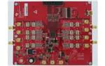
The ADS5296 EVM has eight SMAs vertically mounted on the topside of the board corresponding to eight
analog input channels labeled CHx_XFMR, where x = 1 to 8, as shown in colored boxes of Figure 20.
Channels 5, 6, 7, and 8, highlighted by the yellow box, are configured for octal non-interleaving mode and
are driven through the back-to-back transformers on the top side of the board, while channels 1, 2, 3, and
4, highlighted by the blue box, are disconnected from the DUT. This is evident by the installed 0-ohm
jumper resistors at R210, R399, R209, R386, R208, R394, R207, and R304 and by the uninstalled 0-ohm
resistor jumpers at R378, R379, R155, R154, R166, R165, R168, and R167, respectively.
Figure 20. ADS5296 EVM Octal Non-Interleaving Mode Analog Input SMAs
22
ADS5296, 4-Channel 200-MSPS, and 8-Channel 80-MSPS, Analog-to-Digital
Converter Evaluation Module
Copyright © 2013, Texas Instruments Incorporated
SLAU491 – May 2013
Submit Documentation Feedback
�Hardware and EVM Setup for Testing ADS5296
www.ti.com
The ADS5296 EVM also has four side-mounted SMAs corresponding to four analog input channels
labeled CH1_AMP(1,2), CH2_AMP(3,4), CH3_AMP(5,6), CH4_AMP(7,8) as shown in colored boxes of
Figure 21. Channels 1 and 2, highlighted by the yellow box, are configured for quad non-interleaving mode
and are driven through the amplifiers on the back side of the board, while channels 3 and 4, highlighted by
the blue box, are disconnected from the DUT. This is evident by the installed 0-ohm jumper resistors on
the backside at R80, R81, R324, and ADS5296, 4-Channel 200-MSPS, and 8-Channel 80-MSPS, Analogto-Digital Converter Evaluation Module, and by the uninstalled 0-ohm resistor jumpers on the backside at
R346, R348, R368, and R370, respectively. When an input signal is provided SMA J27, CH1_AMP(1,2), a
switch internal to the ADS5296, selects whether ADC channel 1 or ADC channel 2 is sampled. The
selection depends on the state of GUI control ODD_EVEN_SEL or on the position of header JP2.
Figure 21. ADS5296 EVM Quad Interleaving Mode Analog Input SMAs
SLAU491 – May 2013
Submit Documentation Feedback
ADS5296, 4-Channel 200-MSPS, and 8-Channel 80-MSPS, Analog-to-Digital
Converter Evaluation Module
Copyright © 2013, Texas Instruments Incorporated
23
�Testing ADS5296 EVM
4
www.ti.com
Testing ADS5296 EVM
This section outlines the following three test cases with a sub-section dedicated to each case:
• Capturing a RAMP test pattern
• Capturing a Sinusoidal Input in Octal Non-Interleaving Mode
• Capturing a Sinusoidal Input in Quad Interleaving Mode
Only the minimal software GUI settings required to achieve the above tests will be described in this
section. For a detailed explanation of the ADS5296 software GUI and all its features, please see
Section 5. For a detailed explanation of the High Speed Data Converter Pro software GUI, please consult
the TSW1400 User’s Guide (SLWU079B), available on the Texas Instruments website.
4.1
TSW1400 and ADS5296 GUI Setup
1. With the setup outlined in Figure 18 established, launch the High Speed Data Converter Pro GUI. The
GUI should automatically detect the serial number of the TSW1400 EVM, connected as shown in
Figure 22. Click on OK.
Figure 22. TSW1400 GUI Setup (a)
The message shown in Figure 23 will appear. Click OK.
24
ADS5296, 4-Channel 200-MSPS, and 8-Channel 80-MSPS, Analog-to-Digital
Converter Evaluation Module
Copyright © 2013, Texas Instruments Incorporated
SLAU491 – May 2013
Submit Documentation Feedback
�Testing ADS5296 EVM
www.ti.com
Figure 23. TSW1400 GUI Setup (b)
If instead, the message shown in Figure 24 appears, it indicates that the USB connection to the
TSW1400 EVM is not present. Click OK, then establish a USB connection and repeat step 1.
Figure 24. TSW1400 GUI Setup (c)
2. Select a device by clicking on the Blue arrow in the upper left corner of the HSDCpro GUI. Scroll down
and select ADS5296 as shown in Figure 25.
SLAU491 – May 2013
Submit Documentation Feedback
ADS5296, 4-Channel 200-MSPS, and 8-Channel 80-MSPS, Analog-to-Digital
Converter Evaluation Module
Copyright © 2013, Texas Instruments Incorporated
25
�Testing ADS5296 EVM
www.ti.com
Figure 25. TSW1400 GUI Setup (d)
Click the Yes button to update the ADC firmware on the TSW1400 FPGA as depicted in Figure 26.
Figure 26. TSW1400 GUI Setup (e)
While the firmware is being loaded into the TSW1400 FPGA, the menu shown in Figure 27 will appear.
Figure 27. TSW1400 GUI Setup (f)
Once loaded, the plug-in ADS5296 GUI will appear as a new tab within the HSDCpro GUI as shown in
Figure 28.
26
ADS5296, 4-Channel 200-MSPS, and 8-Channel 80-MSPS, Analog-to-Digital
Converter Evaluation Module
Copyright © 2013, Texas Instruments Incorporated
SLAU491 – May 2013
Submit Documentation Feedback
�Testing ADS5296 EVM
www.ti.com
Figure 28. ADS5296 Plug-in GUI Setup (a)
3. Click on the tab ADS5296 GUI to view the software GUI for the ADS5296. The GUI consists of two
tabs: Read Me First and High Level Test as shown in Figure 29.
SLAU491 – May 2013
Submit Documentation Feedback
ADS5296, 4-Channel 200-MSPS, and 8-Channel 80-MSPS, Analog-to-Digital
Converter Evaluation Module
Copyright © 2013, Texas Instruments Incorporated
27
�Testing ADS5296 EVM
www.ti.com
Figure 29. ADS5296 Plug-in GUI Setup (b)
Clicking on the High Level Test tab shows four sub-tabs: Top Level, Test Pattern, Digital Signal
Processing, and Channel Filter as shown in Figure 30.
28
ADS5296, 4-Channel 200-MSPS, and 8-Channel 80-MSPS, Analog-to-Digital
Converter Evaluation Module
Copyright © 2013, Texas Instruments Incorporated
SLAU491 – May 2013
Submit Documentation Feedback
�Testing ADS5296 EVM
www.ti.com
Figure 30. ADS5296 Plug-in GUI Setup (c)
4. Verify that communication between the ADS5296 EVM and the ADS5296 GUI is established by
toggling either PDN_COMPLETE checkbox or the PDN checkbox highlighted on Figure 30. Checking
either box should make +5-V power supply current drop from ~850 mA to ~563 mA. If the DC current
is approximately 600 mA with both power down boxes unchecked, it indicates that the ADS5296 is not
receiving the sampling clock. Please ensure that the 3-pin headers are configured as described in
Section 3.2. Before continuing, ensure that both power down boxes are left unchecked. At this point,
the GUI is confirmed to be communicating correctly with the EVM and testing can begin.
4.2
Capturing a RAMP Test Pattern
As described in Section 3.1, the LVDS interface between the ADS5296 EVM and the TSW1400 EVM can
be tested using the default EVM configuration and minimal bench equipment.
1. Press on the sub-tab labeled Test Pattern and select RAMP PATTERN within the TEST_PATT menu
as shown in Figure 31.
SLAU491 – May 2013
Submit Documentation Feedback
ADS5296, 4-Channel 200-MSPS, and 8-Channel 80-MSPS, Analog-to-Digital
Converter Evaluation Module
Copyright © 2013, Texas Instruments Incorporated
29
�Testing ADS5296 EVM
www.ti.com
Figure 31. ADS5296 GUI Setup for RAMP Test
2. Perform the following steps highlighted in Figure 32:
(a) Press the ADC tab in HSDCpro
(b) Change the plot type from Real FFT to Codes
(c) Enter 80M in the field labeled ADC Output Data Rate
(d) Press the Capture button
30
ADS5296, 4-Channel 200-MSPS, and 8-Channel 80-MSPS, Analog-to-Digital
Converter Evaluation Module
Copyright © 2013, Texas Instruments Incorporated
SLAU491 – May 2013
Submit Documentation Feedback
�Testing ADS5296 EVM
www.ti.com
Figure 32. HSDCpro GUI Setup for RAMP Test
3. The saw tooth waveform should be captured and displayed as in Figure 33.
SLAU491 – May 2013
Submit Documentation Feedback
ADS5296, 4-Channel 200-MSPS, and 8-Channel 80-MSPS, Analog-to-Digital
Converter Evaluation Module
Copyright © 2013, Texas Instruments Incorporated
31
�Testing ADS5296 EVM
www.ti.com
Figure 33. RAMP Capture
4. By default, Channel 1/8 is the first channel displayed. Use the drop-down menu shown in Figure 34 to
view all 8 channels and confirm that a saw tooth waveform has been captured. Also confirm, in the
menu to the left side, that the min code is 0 and the max code is 4095, corresponding to a 12-bit ADC.
32
ADS5296, 4-Channel 200-MSPS, and 8-Channel 80-MSPS, Analog-to-Digital
Converter Evaluation Module
Copyright © 2013, Texas Instruments Incorporated
SLAU491 – May 2013
Submit Documentation Feedback
�Testing ADS5296 EVM
www.ti.com
Figure 34. RAMP Capture by Channel
5. Zooming into the waveform, as shown in Figure 35, is recommended to ensure that the RAMP
waveform increments 1 ADC code for each subsequent sample.
SLAU491 – May 2013
Submit Documentation Feedback
ADS5296, 4-Channel 200-MSPS, and 8-Channel 80-MSPS, Analog-to-Digital
Converter Evaluation Module
Copyright © 2013, Texas Instruments Incorporated
33
�Testing ADS5296 EVM
www.ti.com
Figure 35. Zoom on RAMP Capture
4.3
Capturing Sinusoidal Input in Octal Non-Interleaving Mode
This section describes the necessary steps to reconfigure the EVM and test setup for capturing a
sinusoidal input with the ADS5296 in octal non-interleaving mode.
1. The RAMP test described in Section 4.2 was performed using an 80-MHz on-board crystal oscillator
(XTAL) for the sampling clock. This clock cannot be used to measure performance of the device as it is
not phase locked to the input signal. The XTAL should be disabled by moving jumper J35 from the
position labeled CDC_3.3V to the position labeled GND in the silkscreen. Also, J38 must change
position from XTAL to CLK_XFMR in the silkscreen to enable the SMA J31 CLK_XFMR. Figure 36
and Figure 37 show the jumper positions before and after this change, respectively.
34
ADS5296, 4-Channel 200-MSPS, and 8-Channel 80-MSPS, Analog-to-Digital
Converter Evaluation Module
Copyright © 2013, Texas Instruments Incorporated
SLAU491 – May 2013
Submit Documentation Feedback
�Testing ADS5296 EVM
www.ti.com
Figure 36. Jumper J35 and J38 positions for Enabled XTAL (default)
SLAU491 – May 2013
Submit Documentation Feedback
ADS5296, 4-Channel 200-MSPS, and 8-Channel 80-MSPS, Analog-to-Digital
Converter Evaluation Module
Copyright © 2013, Texas Instruments Incorporated
35
�Testing ADS5296 EVM
www.ti.com
Figure 37. Jumper J35 and J38 positions for Disabled XTAL
2. With the setup established in Figure 38 and Figure 37, perform the following steps:
(a) Enable the signal generator providing the sampling clock to SMA J31 labeled CLK_XFMR (+5
dBm, 80 MHz)
(b) Enable the signal generator providing the input signal to SMA J15 labeled CH5_XFMR (+15 dbm,
10 MHz). For high-performance results the instrument should have low phase noise and low
harmonic distortion. In addition, a filter is recommended on the input as shown in Figure 38.
(c) The two signal generators in items (a) and (b) above should be phase locked so that coherency is
established. This is achieved connecting the two via a BNC cable. One instrument will provide 10MHz output while the other instrument will receive 10-MHz input.
36
ADS5296, 4-Channel 200-MSPS, and 8-Channel 80-MSPS, Analog-to-Digital
Converter Evaluation Module
Copyright © 2013, Texas Instruments Incorporated
SLAU491 – May 2013
Submit Documentation Feedback
�Testing ADS5296 EVM
www.ti.com
Figure 38. Octal Non-interleaving Mode Hardware Setup
3. Click on ADS5296 GUI tab and ensure that the TEST_PATT field is set to None, as shown in
Figure 39.
SLAU491 – May 2013
Submit Documentation Feedback
ADS5296, 4-Channel 200-MSPS, and 8-Channel 80-MSPS, Analog-to-Digital
Converter Evaluation Module
Copyright © 2013, Texas Instruments Incorporated
37
�Testing ADS5296 EVM
www.ti.com
Figure 39. ADS5296 GUI Setup for Octal Non-Interleaving Mode
4. Click on the ADC tab and perform the following steps as illustrated in Figure 40.
(a) In the box labeled ADC Input Target Frequency input 10M
(b) In the drop down menus set Real FFT, Channel 5/8, Rectangular
(c) Check the box labeled Auto Calculation of Coherent Frequencies (Note: the ADC Input Target
Frequency box will automatically be updated with the required coherent frequency)
(d) Change the frequency on the signal generator providing the analog input signal to match the value
shown in the ADC Input Target Frequency box (9.99877930 MHz)
(e) Press the Capture button
38
ADS5296, 4-Channel 200-MSPS, and 8-Channel 80-MSPS, Analog-to-Digital
Converter Evaluation Module
Copyright © 2013, Texas Instruments Incorporated
SLAU491 – May 2013
Submit Documentation Feedback
�Testing ADS5296 EVM
www.ti.com
Figure 40. HSDCpro GUI Setup for Octal Non-Interleaving Mode (b)
5. The plot will update as shown in Figure 41. Take note of the Fund. value in the left panel highlighted in
RED in Figure 41. This value is dependent on the signal level set on the signal generator feeding the
input signal to J15. It also depends on cable loss and filter insertion loss which can vary among parts.
If needed, reset the signal amplitude (level) until the Fund. value is approximately –1.0 dBFs, as this is
the condition for which the datasheet specifications are set. In the example shown here, the input level
should be changed from 15.0 dBm to 15.1 dBm and then a capture retaken.
SLAU491 – May 2013
Submit Documentation Feedback
ADS5296, 4-Channel 200-MSPS, and 8-Channel 80-MSPS, Analog-to-Digital
Converter Evaluation Module
Copyright © 2013, Texas Instruments Incorporated
39
�Testing ADS5296 EVM
www.ti.com
Figure 41. Octal Non-Interleaving Mode Capture 1
6. After re-capturing, the Fund. value is now closer to –1.0 dBFs as shown in Figure 42.
40
ADS5296, 4-Channel 200-MSPS, and 8-Channel 80-MSPS, Analog-to-Digital
Converter Evaluation Module
Copyright © 2013, Texas Instruments Incorporated
SLAU491 – May 2013
Submit Documentation Feedback
�Testing ADS5296 EVM
www.ti.com
Figure 42. Octal Non-Interleaving Mode Capture 2
The SNR computed is highly dependent on the phase noise of the input signal source. Figure 42 and
Figure 43 are with the exact same configuration, the only difference being the instrument used to
provide the 10-MHz input signal. A 4.5 dB difference in the computed SNR is observed and is
attributed solely to the integrity of the input signal, specifically the close-in phase noise.
SLAU491 – May 2013
Submit Documentation Feedback
ADS5296, 4-Channel 200-MSPS, and 8-Channel 80-MSPS, Analog-to-Digital
Converter Evaluation Module
Copyright © 2013, Texas Instruments Incorporated
41
�Testing ADS5296 EVM
www.ti.com
Figure 43. Octal Non-Interleaving Mode Capture 3
A software filter can be used to remove the contribution of phase noise using the HSDCpro menu Test
Options => Frequency Bins as shown in Figure 44.
42
ADS5296, 4-Channel 200-MSPS, and 8-Channel 80-MSPS, Analog-to-Digital
Converter Evaluation Module
Copyright © 2013, Texas Instruments Incorporated
SLAU491 – May 2013
Submit Documentation Feedback
�Testing ADS5296 EVM
www.ti.com
Figure 44. HSDCpro Software Filtering
Change the default values from 0 to 500 as shown in Figure 45.
SLAU491 – May 2013
Submit Documentation Feedback
ADS5296, 4-Channel 200-MSPS, and 8-Channel 80-MSPS, Analog-to-Digital
Converter Evaluation Module
Copyright © 2013, Texas Instruments Incorporated
43
�Testing ADS5296 EVM
www.ti.com
Figure 45. HSDCpro Software Filtering Menu
The plot and all calculations will be updated accounting for these removed bins as shown in Figure 46.
The SNR is now very close to the Software Filtering Menu SNR shown in Figure 43 using a superior
instrument.
44
ADS5296, 4-Channel 200-MSPS, and 8-Channel 80-MSPS, Analog-to-Digital
Converter Evaluation Module
Copyright © 2013, Texas Instruments Incorporated
SLAU491 – May 2013
Submit Documentation Feedback
�Testing ADS5296 EVM
www.ti.com
Figure 46. HSDCpro Capture with Software Filtering
4.4
Capturing Sinusoidal Input in Quad Interleaving Mode
This section describes the necessary steps to reconfigure the EVM and test setup for capturing a
sinusoidal input with the ADS5296 in quad interleaving mode.
1. Setup the EVM as shown in Figure 47 by performing the following steps:
(a) The signal generator providing the sampling clock to SMA J31 labeled CLK_XFMR should be
changed from 80 MHz to 200 MHz. (+5 dBm, 200 MHz)
(b) Provide the input signal to SMA J27 labeled CH1_AMP(1,2) (+15.1 dbm, 10 MHz). For highperformance results the instrument should have low phase noise and low harmonic distortion. In
addition, a filter is recommended on the input as shown in Figure 47.
(c) The two signal generators in items (a) and (b) above should be phase locked. This is achieved
connecting the two via a BNC cable. One instrument will provide 10-MHz output while the other
instrument will receive 10-MHz input.
SLAU491 – May 2013
Submit Documentation Feedback
ADS5296, 4-Channel 200-MSPS, and 8-Channel 80-MSPS, Analog-to-Digital
Converter Evaluation Module
Copyright © 2013, Texas Instruments Incorporated
45
�Testing ADS5296 EVM
www.ti.com
Figure 47. Quad-Interleaving Mode Hardware Setup
2. From the ADS5296 GUI, Top Level tab, make the following changes as shown in Figure 48. With this
configuration the ADS5296 will be sampling channel 1 since the ODD_EVEN_SEL is set to ODD in the
software GUI.
(a) Change EN_BIT_SER to 10-bits
(b) Change EN_INTERLEAVE to Enabled
(c) Change ADC Output Data Rate to 200M
(d) Reset the signal generator providing the analog input signal to the new coherent frequency shown
in the ADC Input Target Frequency box (9.98229980 MHz)
(e) Return to ADC tab and hit Capture.
46
ADS5296, 4-Channel 200-MSPS, and 8-Channel 80-MSPS, Analog-to-Digital
Converter Evaluation Module
Copyright © 2013, Texas Instruments Incorporated
SLAU491 – May 2013
Submit Documentation Feedback
�Testing ADS5296 EVM
www.ti.com
Figure 48. Quad-Interleaving Mode GUI Setup
Figure 49 shows that the Fund. value is ~0.8 dB low.
SLAU491 – May 2013
Submit Documentation Feedback
ADS5296, 4-Channel 200-MSPS, and 8-Channel 80-MSPS, Analog-to-Digital
Converter Evaluation Module
Copyright © 2013, Texas Instruments Incorporated
47
�Testing ADS5296 EVM
www.ti.com
Figure 49. Quad-Interleaving Mode Capture 1
Increasing the output power from the signal generator by +0.8 dB and re-capturing results in Figure 50.
48
ADS5296, 4-Channel 200-MSPS, and 8-Channel 80-MSPS, Analog-to-Digital
Converter Evaluation Module
Copyright © 2013, Texas Instruments Incorporated
SLAU491 – May 2013
Submit Documentation Feedback
�Testing ADS5296 EVM
www.ti.com
Figure 50. Quad-Interleaving Mode Capture 2
For an interleaving ADC, there exists a spur at Fs/2-Fin, which is commonly referred to as the
interleaving spur. As seen in the previous capture, this spur is the Worst Spur in the Nyquist band. The
HSDCpro GUI auto-calculates the location of this spur in the menu Test Options → Notch Frequency
Bins and allows for removal this bin from the plot if desired as shown in Figure 51.
SLAU491 – May 2013
Submit Documentation Feedback
ADS5296, 4-Channel 200-MSPS, and 8-Channel 80-MSPS, Analog-to-Digital
Converter Evaluation Module
Copyright © 2013, Texas Instruments Incorporated
49
�ADS5296 GUI in Detail
www.ti.com
Figure 51. Quad-Interleaving Mode Fs/2 - Fin Software Filtering
5
ADS5296 GUI in Detail
This section is dedicated to explaining the ADS5296 GUI, and all its features, in depth. There is a section
dedicated to each tab of the ADS5296 software GUI: Read Me First, Top Level, Test Pattern, Digital
Signal Processing, and Channel Filter.
After launching HSDCpro, the ADS5296 GUI can be invoked in two ways: normal mode or simulation
mode. Simulation mode is used in the event that no ADS5296 EVM is available. When this is the case, the
message shown in Figure 52 appears shortly after choosing the ADS5296 device in HSDCpro.
50
ADS5296, 4-Channel 200-MSPS, and 8-Channel 80-MSPS, Analog-to-Digital
Converter Evaluation Module
Copyright © 2013, Texas Instruments Incorporated
SLAU491 – May 2013
Submit Documentation Feedback
�ADS5296 GUI in Detail
www.ti.com
Figure 52. ADS5296 GUI Simulation Mode
The user is given the choice to Continue in Simulation or Stop & Close. If Continue in Simulation is
selected the ADS5296 GUI will install and all controls will “appear” to function as normal including the
DIGITAL WAVEFORM GRAPH-WRITE which shows what is being written to the serial interface. When in
Simulation mode the checkbox at the top right corner of the GUI will remain checked as shown in
Figure 53.
Figure 53. ADS5296 GUI Simulation Mode Checkbox Indicator
As Figure 53 shows, within the ADS5296 GUI tab there are two high level tabs called Read Me First and
High Level Test. The Read Me First tab contains general information while the High Level Test tab holds
four sub-tabs containing all SPI controls.
SLAU491 – May 2013
Submit Documentation Feedback
ADS5296, 4-Channel 200-MSPS, and 8-Channel 80-MSPS, Analog-to-Digital
Converter Evaluation Module
Copyright © 2013, Texas Instruments Incorporated
51
�ADS5296 GUI in Detail
5.1
www.ti.com
Read Me First Tab
After launching HSDCpro and selecting the ADS5296 firmware to load, as depicted in Figure 22 through
Figure 27, the ADS5296 GUI presents the Read Me First tab initially as shown in Figure 53 (Simulation
checkbox will be unchecked if EVM is connected).
The two sections in the upper right corner of this tab, SIMULATION and RECORD/PLAYBACK
COMMAND SEQUENCE, are common to all tabs within the ADS5296 GUI. The RECORD/PLAYBACK
COMMAND SEQUENCE section allows the user to:
• Record a sequence of commands
• Save the sequence that was recorded to a file
• Playback a sequence that was saved from a file
Once the Record Sequence button is pressed, the sequence of commands, or SPI writes, will appear
chronologically in the Recorded Sequence box at the bottom of this section as depicted in Figure 54.
Figure 54. RECORD/PLAYBACK COMMAND SEQUENCE (a)
Hitting the Save Sequence button brings up dialog box to save the sequence to the GUI install path:
C:\Program Files (x86)\Texas Instruments\ADS5295_96\Recorded Sequences\ADS5296 Recorded Sequences
To playback a saved sequence, hit the Playback Sequence button and choose the sequence to execute.
As shown in Figure 55, there are nine sequences pre-defined in this folder corresponding to the nine
OPERATING MODES OF ADS5296 shown in the table at the bottom of the tab. The table includes the
maximum sampling clock speed supported for each mode. Ensure that the clock source is within this limit
for a particular mode.
52
ADS5296, 4-Channel 200-MSPS, and 8-Channel 80-MSPS, Analog-to-Digital
Converter Evaluation Module
Copyright © 2013, Texas Instruments Incorporated
SLAU491 – May 2013
Submit Documentation Feedback
�ADS5296 GUI in Detail
www.ti.com
Figure 55. RECORD/PLAYBACK COMMAND SEQUENCE (b)
5.2
Top Level Tab
The left-most sub-tab within the High Level Test tab is Top Level. As shown in Figure 56, this tab contains
five sections which are highlighted in red: OUTPUT INTERFACE MODES, GENERAL SETUP,
POWERDOWN MODES, CUSTOM WRITE/READ and DEVICE PIN CONTROL. In the right border of this
tab is a section called DIGITAL WAVEFORM GRAPH-WRITE.
SLAU491 – May 2013
Submit Documentation Feedback
ADS5296, 4-Channel 200-MSPS, and 8-Channel 80-MSPS, Analog-to-Digital
Converter Evaluation Module
Copyright © 2013, Texas Instruments Incorporated
53
�ADS5296 GUI in Detail
www.ti.com
Figure 56. RECORD/PLAYBACK COMMAND SEQUENCE (c)
This section, like Simulation and RECORD/PLAYBACK COMMAND SEQUENCE above it, remains fixed
in the border when switching among the sub-tabs within the High Level Test tab. The DIGITAL
WAVEFORM GRAPH-WRITE section, shown in Figure 57, tracks all SPI writes from the GUI and displays
them here.
Figure 57. DIGITAL WAVEFORM GRAPH-WRITE
The OUTPUT INTERFACE MODES section contains all device controls related to the format of the data to
be output across the LVDS interface. Figure 58 shows the drop-down menu for EN_SER_BIT which
selects the resolution of he ADC. The button to the right of this menu, and seen throughout the GUI, is an
info button and displays relevant information from the datasheet.
54
ADS5296, 4-Channel 200-MSPS, and 8-Channel 80-MSPS, Analog-to-Digital
Converter Evaluation Module
Copyright © 2013, Texas Instruments Incorporated
SLAU491 – May 2013
Submit Documentation Feedback
�ADS5296 GUI in Detail
www.ti.com
Figure 58. EN_SER_BIT Drop-Down Menu
When the info button next the EN_SER_BIT control is selected with 12-bits selected the information
shown in Figure 59 is presented.
SLAU491 – May 2013
Submit Documentation Feedback
ADS5296, 4-Channel 200-MSPS, and 8-Channel 80-MSPS, Analog-to-Digital
Converter Evaluation Module
Copyright © 2013, Texas Instruments Incorporated
55
�ADS5296 GUI in Detail
www.ti.com
Figure 59. EN_SER_BIT Info Button
The GENERAL SETUP section shown in Figure 60 contains several controls, the top most being the RST
button, or software reset. When this button is pressed all serial registers are updated to their default state
and the bit is reset automatically. The button EN_HIGH_ADDR is required to enable the EN_EXT_REF
button below it. This dependency represents the implementation in the design itself. The ADS5296 device
supports both internal and external reference mode to set the full-scale of the ADC. The
EN_INTERLEAVE button is used to enable and disable the interleaving mode, thus, switching the device
between a quad channel ADC and an octal ADC, respectively. When EN_INTERLEAVE is enabled, the
EN_MUX_REG button becomes active (ungreyed) and determines whether the selection to sample odd
numbered channels or even numbered channels in interleave mode comes from the SPI or from the
INTERLEAVE_MUX pin of the device. If ODD/EVEN SEL by SPI is selected, the last button of this
section, ODD_EVEN_SEL, becomes active and determines this. If ODD/EVEN SEL by Pin is selected
instead, the selection to sample odd numbered channels or even numbered channels in interleave mode
comes from the state of the INTERLEAVE_MUX button in the DEVICE PIN CONTROL section of this tab.
56
ADS5296, 4-Channel 200-MSPS, and 8-Channel 80-MSPS, Analog-to-Digital
Converter Evaluation Module
Copyright © 2013, Texas Instruments Incorporated
SLAU491 – May 2013
Submit Documentation Feedback
�ADS5296 GUI in Detail
www.ti.com
Figure 60. GENERAL SETUP Section of Top Level Tab
The CUSTOM WRITE/READ section of the Top Level tab allows for custom writing to the serial interface
of the ADS5296 as well as reading back register values. When a valid register address and value is
provided the corresponding control will automatically update to reflect the current state of the device. In
the example in Figure 61, the value of PHASE_DDR updated as a result of writing x8000 to reg42.
Figure 61. CUSTOM WRITE/READ Example
5.3
Test Pattern Tab
The second sub-tab, shown in Figure 62, is Test Pattern. Within this tab, the user has the control of all the
test patterns intrinsic to the device as described in the three sections of this tab: PSEUDO-RANDOM
BINARY SEQUENCE (PRBS), CUSTOM FRAME CLOCK PATTERN, TEST PATTERN MODES.
SLAU491 – May 2013
Submit Documentation Feedback
ADS5296, 4-Channel 200-MSPS, and 8-Channel 80-MSPS, Analog-to-Digital
Converter Evaluation Module
Copyright © 2013, Texas Instruments Incorporated
57
�ADS5296 GUI in Detail
www.ti.com
Figure 62. Test Pattern Tab
The PRBS section shows all its controls to be greyed an unselectable except for PRBS_TP_EN checkbox.
Once this box is checked all the remaining controls are accessible as shown in Figure 63. The info buttons
provide details on the definition of each control.
Figure 63. PRBS Section Enabled
The TEST PATTERN MODES section contains commonly used test patterns under the TEST_PATT dropdown menu as shown in Figure 64. All of these patterns are generated internal to the ADS5296 device
and provided on all channels simultaneously.
58
ADS5296, 4-Channel 200-MSPS, and 8-Channel 80-MSPS, Analog-to-Digital
Converter Evaluation Module
Copyright © 2013, Texas Instruments Incorporated
SLAU491 – May 2013
Submit Documentation Feedback
�ADS5296 GUI in Detail
www.ti.com
Figure 64. TEST PATTERN MODES Section
5.4
Digital Signal Processing Tab
The Digital Signal Processing tab contains five sections as shown in Figure 65: CHANNEL AVERAGING,
CHANNEL_GAIN, LOW FREQUENCY NOISE SUPPRESSION, SWAP ANALOG INPUTS, and
INPUT/OUTPUT MAPPING.
Figure 65. Digital Signal Processing Tab
SLAU491 – May 2013
Submit Documentation Feedback
ADS5296, 4-Channel 200-MSPS, and 8-Channel 80-MSPS, Analog-to-Digital
Converter Evaluation Module
Copyright © 2013, Texas Instruments Incorporated
59
�ADS5296 GUI in Detail
www.ti.com
The CHANNEL AVERAGING function is enabled by the checkbox labeled EN_CHANNEL_AVG as shown
in Figure 66. Once checked, the drop-down menus within the section become un-greyed and active as
shown. The drop-down menu shown in Figure 66 corresponds to the choices available to output onto
OUT1 of the device.
Figure 66. Digital Signal Processing Tab
With Zero selected from the drop-down menu, the output to Channel 1 is fixed at maximum ADC code.
With ADC CH1 selected, the normal Channel 1 output is captured as in the case when channel averaging
is disabled. With AVG ADC CH1,2 selected, the Channel 1 output now contains the averaged output
Channel 1 and Channel 2 which improves SNR by approximately 4.6 dB. Finally, with AVG ADC
CH1,2,3,4 selected the output of Channel 1 contains the average of the four channels which improves
SNR by 5.4 dB typically. (Note: pressing the info button in this section shows the graphic in Figure 67.
This table, from the datasheet, shows only the averaging options for each output, which is either a twochannel average or a four-channel average. Not shown in the table are the two other options appearing
the GUI drop-down menus, ZERO and ADC CHx, which represents the actual design implementation.)
Figure 67. Channel Averaging Info Button
60
ADS5296, 4-Channel 200-MSPS, and 8-Channel 80-MSPS, Analog-to-Digital
Converter Evaluation Module
Copyright © 2013, Texas Instruments Incorporated
SLAU491 – May 2013
Submit Documentation Feedback
�ADS5296 GUI in Detail
www.ti.com
The INPUT/OUTPUT MAPPING section allows the user to remap the analog input channels to any of the
digital output channels. The implementation in silicon allows for all combinations of mapping. However,
because each combination requires a unique firmware or DLL configuration, the GUI limits the number of
combinations available in mapping. To un-grey and enable this section check the ENABLE MAPPING
checkbox as shown in Figure 68.
Figure 68. INPUT/OUTPUT MAPPING with EN_INTERLEAVE = 0
The default state of this section shows that output channels 1–4 have mapped the signal that is sampled
at analog input channel 1, while channels 5–8 have mapped the signal that is sampled at analog input
channel 8. This menu applies if interleaving is disabled. If interleaving is enabled on the Top Level tab,
then the mapping options reflects this as shown in Figure 69.
Figure 69. INPUT/OUTPUT MAPPING with EN_INTERLEAVE = 1
The remaining sections of the Digital Signal Processing tab are straightforward and explained by the info
buttons provided.
5.5
Channel Filter Tab
The last tab is Channel Filter and contains the controls for the decimation filters as well as the integrated
high pass filters. As shown in Figure 70, the controls have interdependencies, reflecting the actual silicon
implementation.
SLAU491 – May 2013
Submit Documentation Feedback
ADS5296, 4-Channel 200-MSPS, and 8-Channel 80-MSPS, Analog-to-Digital
Converter Evaluation Module
Copyright © 2013, Texas Instruments Incorporated
61
�ADS5296 GUI in Detail
www.ti.com
Figure 70. Channel Filter Tab
Checking the EN_DIG_FILTER box causes the USE_FILTER control to become un-greyed and enabled
for all eight channels as shown in Figure 71.
62
ADS5296, 4-Channel 200-MSPS, and 8-Channel 80-MSPS, Analog-to-Digital
Converter Evaluation Module
Copyright © 2013, Texas Instruments Incorporated
SLAU491 – May 2013
Submit Documentation Feedback
�ADS5296 GUI in Detail
www.ti.com
Figure 71. EN_DIG_FILTER = 1
At this point, the user can invoke the high pass filter for any channel by checking the box HPF_EN_CH.
The box just below labeled HPF_CORNER_CH becomes active, as shown in Figure 72, and the corner
frequency can be set to one of sixteen values, with zero being the highest corner frequency available.
Figure 72. Channel 5 High Pass Filter Enabled
The ADS526’s digital processing block includes the option to filter and decimate the ADC outputs digitally.
Various decimation rates and filters are supported including decimation by 2, 4, or 8, low-pass, high-pass,
and band-pass filters. To invoke this block the USE_FILTER box must be checked, thus, enabling all
controls associated with the digital and decimation filters as shown in Figure 73.
SLAU491 – May 2013
Submit Documentation Feedback
ADS5296, 4-Channel 200-MSPS, and 8-Channel 80-MSPS, Analog-to-Digital
Converter Evaluation Module
Copyright © 2013, Texas Instruments Incorporated
63
�ADS5296 GUI in Detail
www.ti.com
Figure 73. Channel 1 Digital Filter Enabled
The user has the option to use pre-defined filter coefficients or define custom coefficients. When Use PreStored Filter Coeff is selected, one of six pre-defined filter types, depending on the state of
FILTER_TYPE_SEL, will be configured. The Digital Filters Table of the datasheet describes these
configurations and is available through the info button on this tab. In addition, the six pre-defined filters are
presented graphically at the bottom of the Channel Filter tab when the channel chosen to view (from View
Pre-Stored/Custom Filter Coeff section at bottom left) has Use Pre-Stored selected.
Figure 74. Channel 1 Pre-Stored Digital Filter Enabled
If, instead, Enable Custom Filter is selected, then all controls associated with the pre-defined filters
become inactive as shown in Figure 75. In addition, the graphs of the pre-stored filters are replaced with
the twelve registers that hold the twelve, 12-bit, signed coefficients for one custom filter.
64
ADS5296, 4-Channel 200-MSPS, and 8-Channel 80-MSPS, Analog-to-Digital
Converter Evaluation Module
Copyright © 2013, Texas Instruments Incorporated
SLAU491 – May 2013
Submit Documentation Feedback
�ADS5296 GUI in Detail
www.ti.com
Figure 75. Channel 1 Custom Digital Filter Enabled
Because of the large number of inputs required to define all eight custom filters (8 × 12 = 96 coefficients),
the GUI provides a means for loading coefficients from a text file, saving coefficients to a text file, and
resetting filter coefficient values.. This control is located in the bottom right corner of Channel Filter tab. As
shown in Figure 76, Reset Channels can be applied to only Pre-stored Filters, only Custom Filters, or to
all filters.
Figure 76. Reset Channels on Channel Filter Tab
The Save/Load Custom Filter Coeffs drop-down menu, as shown in Figure 77, can be used to save the
currently displayed channel’s custom coefficients to a file or all channels’ custom coefficients to a file.
SLAU491 – May 2013
Submit Documentation Feedback
ADS5296, 4-Channel 200-MSPS, and 8-Channel 80-MSPS, Analog-to-Digital
Converter Evaluation Module
Copyright © 2013, Texas Instruments Incorporated
65
�ADS5296 GUI in Detail
www.ti.com
Figure 77. Save/Load Custom Filter Coeffs on Channel Filter Tab
Likewise, one can load the custom coefficients for the current channel or for all channels. The current
channel is indicated on the lower left corner in the View Pre-stored/Custom Filter Coeff section shown in
Figure 78. Only those channels whose USE_FILTER bit are enabled are active, and thus, available for
viewing.
Figure 78. View Filter Coeffs
66
ADS5296, 4-Channel 200-MSPS, and 8-Channel 80-MSPS, Analog-to-Digital
Converter Evaluation Module
Copyright © 2013, Texas Instruments Incorporated
SLAU491 – May 2013
Submit Documentation Feedback
�ADS5296 EVM Schematics
www.ti.com
6
ADS5296 EVM Schematics
PLACE 0.1UF CLOSE TO DEVICE AVDD PINS
2
C10
0.1uF
1
2
J8A
+1.8V_AVDD
1
+1.8V_AVDD
GND
C12
0.1uF
GND
TP9 TP2
VCM
GND
OUT8M
OUT8P
3
GND
1
+1.8V_AVDD
JP2
2
JP14
ODD
OUT7M
OUT7P
3
INTERLEAVE_MUX
1
EVEN
EVM
2
FTDI
OUT6M
OUT6P
R3
0Ohm
OUT5M
OUT5P
C18
2
1
LCLKM
LCLKP
0.1uF
SDOUT
+1.8V_AVDD
REFT
REFB
+1.8V_AVDD
C11
2
1
IN2_P
IN2_M
IN3_P
IN3_M
IN4_P
IN4_M
1
R46
2
10 ohm
2
OUT1P
OUT1M
Z_SH-H4
R6
49.9 Ohm
J18
1
A M S
4
3
2
5
D N E
GND
IN8_M
IN8_P
48
47
46
45
44
43
42
41
40
39
38
37
36
35
34
33
ADCLKM
ADCLKP
OUT4M
OUT4P
OUT3M
OUT3P
OUT2M
OUT2P
IN7_M
IN7_P
OUT1M
OUT1P
IN6_M
IN6_P
IN5_M
IN5_P
+1.8V_LVDD C20
2
1
OUT8M
OUT8P
1
GND
GND
GND
GND
GND
1
3
5
7
9
11
13
15
17
19
21
23
25
27
29
31
33
35
37
39
41
43
45
47
49
51
53
55
57
59
121
123
J8B
U1
IN8_N
IN8_P
AGND
IN7_N
IN7_P
AGND
IN6_N
IN6_P
AGND
IN5_N
IN5_P
AGND
LGND
LVDD
OUT8N
OUT8P
GND
GND
1
3
5
7
9
11
13
15
17
19
21
23
25
27
29
31
33
35
37
39
41
43
45
47
49
51
53
55
57
59
GND
0.1uF
OUT2P
OUT2N
OUT3P
OUT3N
OUT4P
OUT4N
ADCLKP
ADCLKN
LCLKP
LCLKN
OUT5P
OUT5N
OUT6P
OUT6N
OUT7P
OUT7N
R53
10K Ohm
IN1_P
IN1_N
AGND
IN2_P
IN2_N
AGND
IN3_P
IN3_N
AGND
IN4_P
IN4_N
LGND
PDN
LGND
OUT1P
OUT1N
17
OUT2P
OUT2M
18
OUT3P
19
OUT3M
20
21
OUT4P
22
OUT4M
ADCLKP 23
ADCLKM 24
LCLKP 25
LCLKM 26
OUT5P
27
OUT5M
28
OUT6P
29
OUT6M
30
OUT7P
31
OUT7M
32
PD
1
2
3
4
5
6
7
8
9
10
11
12
13
14
15
16
2
4
6
8
10
12
14
16
18
20
22
24
26
28
30
32
34
36
38
40
42
44
46
48
50
52
54
56
58
60
3
1
GND
0.1uF
GND
RESET
SCLK
SDATA
CSZ
AVDD
CLKN
CLKP
AVDD
INTERLEAVE_MUX
REFT
REFB
VCM
SDOUT
NC
AVDD
SYNC
IN1_P
IN1_M
GND
122
124
GND
64
63
62
61
60
59
58
57
56
55
54
53
52
51
50
49
CLKN
CLKP
+1.8V_AVDD
JP3
1
2
56.2K Ohm
JP1
ADCRESETZ
SCLK
SDATA
CSZ
1
2 R400
1
2
2
GND
R56
10K Ohm
65
2
4
6
8
10
12
14
16
18
20
22
24
26
28
30
32
34
36
38
40
42
44
46
48
50
52
54
56
58
60
GND
62
64
66
68
70
72
74
76
78
80
82
84
86
88
90
92
94
96
98
100
102
104
106
108
110
112
114
116
118
120
GND
126
128
GND
62
64
66
68
70
72
74
76
78
80
82
84
86
88
90
92
94
96
98
100
102
104
106
108
110
112
114
116
118
120
GND
GND
61
63
65
67
69
71
73
75
77
79
81
83
85
87
89
91
93
95
97
99
101
103
105
107
109
111
113
115
117
119
GND
GND
61
63
65
67
69
71
73
75
77
79
81
83
85
87
89
91
93
95
97
99
101
103
105
107
109
111
113
115
117
119
J8B_107_PD
J8B_109_INT_MUX
J8B_111_ADCRESET
J8B_113_SDOUT
J8B_115_CSZ
J8B_117_SDATA
J8B_119_SCLK
125
127
GND
Figure 79. ADS5296 Schematic, Sheet 1 of 9
SLAU491 – May 2013
Submit Documentation Feedback
ADS5296, 4-Channel 200-MSPS, and 8-Channel 80-MSPS, Analog-to-Digital
Converter Evaluation Module
Copyright © 2013, Texas Instruments Incorporated
67
�ADS5296 EVM Schematics
2
www.ti.com
SE
J39
1
3
DIFF
1
2 R402
2 1
0Ohm
2
0.1uF
2
S M A
XTAL
SMA
J31
1
1
3
C59
J38
6
T15
1
CLKN
R45
100
1
2
J40
C61
XTAL_CDC
2
C294
1uF
0.1uF
2 R403
2 1
0Ohm
1
CLKP
GND
XTAL
2
U2
1
GND
J36
1
3
J35 GND
1
GND
2
SE
DIFF
R48
100
3
C60
0.1uF
1
3
3
TC4-1WG2+
21
4
GND
CDC_3.3V
1
2
2
4
3
2
5
E N D
OUTPUT
3
Tri-State
GND
ECS-3953M-800-BN
CDC_3.3V
GND
4
3
2
5
C124
2
0.1uF
GND
GND
2
3
4
13
14
15
INP
INN
NC1
NC2
NC3
NC4
NC5
NC6
OUTP0
OUTN0
OUTP1
OUTN1
GND
GND
EP_GND
2 1
2
2 1
2
GND
9
10
11
12
1
16
1
6
7
1
8
R188
0 ohm
DNI
17
CDCLVP1102
2 R184
2 1
0 ohm
DNI
1
2 R185
2 1
0 ohm
DNI
1
R183
0 ohm
DNI
2 1
1
E N D
VAC_REF
2
S M A
1
1
GND U21
5
VCC
J33
R182
0 ohm
DNI
R180
0 ohm
DNI
C126
0.1uF
1
2
C125
0.1uF
2 1
XTAL
2
CLK CDC
1
1
3
CDC_3.3V CDC_3.3V
J37
2
2
VDD
1
1
2
4
GND
GND
GND
Figure 80. ADS5296 Schematic, Sheet 2 of 9
68
ADS5296, 4-Channel 200-MSPS, and 8-Channel 80-MSPS, Analog-to-Digital
Converter Evaluation Module
Copyright © 2013, Texas Instruments Incorporated
SLAU491 – May 2013
Submit Documentation Feedback
�ADS5296 EVM Schematics
www.ti.com
VCM
2
1
2
4
1
GND
GND
GND
R60
12.4 Ohm
R38
GND
C237
1
2
C52
220pF
DNI
R153 2
1
1
2
T33
1
1
2
5
5
2
1
6
4
3
ADT4-1WT+
GND
C243
0.1uF
ADT4-1WT+
R63
12.4 Ohm
C269
2
C53
220pF
DNI
10 ohm
GND
2
3
1
C266
1
2
0.1uF
GND
GND
0.1uF
1 2
GND
1
2
ADT4-1WT+
C242
0.1uF
2
R61
12.4 Ohm
2
GND
C250
0.1uF
1
ADT4-1WT+
4
2
GND
6
1
1
T32
4
6
2
5
5
2
1
6
4
3
1
2
T29
1
1
R155 2
1 2
0 ohm
DNI
R42
24.9 Ohm
R67
12.4 Ohm
C46
1
ADT4-1WT+
IN2_P
GND
C245
0.1uF
ADT4-1WT+
R65
12.4 Ohm
GND
C246
0.1uF
2
R1662
1 2
0 ohm
DNI
IN3_P
2
0.1uF
GND
GND
C54
220pF
DNI
R1672
1 2
0 ohm
DNI
R384
0Ohm
1
IN4_M
C273
6.8 pF
R43
GND
24.9 Ohm
C272
1
2
10 ohm
0.1uF
R381
0Ohm
R159 2 1
10 ohm
R87
1
C58
220pF
DNI
C267
6.8 pF
GND
R39 GND
24.9 Ohm
C55
220pF
DNI
2 3
0.1uF
1
5
1 1
2
5
S M A
E N D
C45
2
1 2
2
1
2
4
3
2
5
1
R62
12.4 Ohm
C249
1
1
J19
C271
2
0.1uF
2
T31
1
SMA_CH4_XFMR
1
6
R37
24.9 Ohm
R154 2 IN2_M
1 2
0 ohm
DNI
R380
0Ohm
4
3
2
5
4
0.1uF
R383
0Ohm
R160 2 1
1
0.1uF
1
1
T27
E N D
2
10 ohm
2
S M A
C247
1 1
2 3
R85
1
2
J17
C270
6.8 pF
VCM
C56
220pF
DNI
0.1uF
2
R41
GND
24.9 Ohm
GND
C244
0.1uF
VCM
SMA_CH2_XFMR
C44
1
1
GND
C265
1
2
R40
24.9 Ohm
R64
12.4 Ohm
GND
R3782 IN1_P
1 2
0 ohm
DNI
10 ohm
0.1uF
6
0.1uF
R377
0Ohm
GND
24.9 Ohm
1
C240
0.1uF
1
C239
0.1uF
ADT4-1WT
2
2
ADT4-1WT
GND
3
2
6
4
0.1uF
C238
6.8 pF
2
0.1uF
1
T28
1
5
2 3
2
5
C248
1 1
R1652 IN3_M
1 2
0 ohm
DNI
R382
0Ohm
1
1
2
J16
S M A
E N D
C43
2
10 ohm
2
4
3
2
5
R36
24.9 Ohm
R59
12.4 Ohm
R86
1
C57
220pF
DNI
1
1
2
T30
0.1uF
2
6
SMA_CH3_XFMR
1
4
1
2
T26
0.1uF
R379 2 IN1_M
1 2
0 ohm
DNI
R376
0Ohm
2
10 ohm
1
C235
2 3
E N D
R35
1
C51
220pF
DNI
4
3
2
5
1 1
2
J14
S M A
0.1uF
C268
1
2
1
SMA_CH1_XFMR
VCM
1
C236
1
2
1
R385
0Ohm
R161 2 1
10 ohm
R1682 IN4_P
1 2
0 ohm
DNI
Figure 81. ADS5296 Schematic, Sheet 3 of 9
SLAU491 – May 2013
Submit Documentation Feedback
ADS5296, 4-Channel 200-MSPS, and 8-Channel 80-MSPS, Analog-to-Digital
Converter Evaluation Module
Copyright © 2013, Texas Instruments Incorporated
69
�ADS5296 EVM Schematics
www.ti.com
VCM
R133
12.4 Ohm
2
1
R210
0Ohm
R172 2
1
1
1
1
GND
6
4
GND
IN5_P
C276
0.1uF
3
R128
12.4 Ohm
1
C283
2
C84
220pF
DNI
R68
24.9 Ohm
R129
12.4 Ohm
2
C261
0.1uF
2
0.1uF
2
C286
1
GND
R132
24.9 Ohm
GND
C80
220pF
DNI
T37
4
6
T40
1
1
R171
2
1
C86
220pF
DNI
2
5
5
2
GND
R209
0Ohm
IN6_P
6
4
C49
1
GND
C257
0.1uF
R127
12.4 Ohm
GND
C258
0.1uF
1
10 ohm
GND
3
C280
2
0.1uF
GND
C77
220pF
DNI
R304
0Ohm
IN8_M
R390
0Ohm
R57
24.9 Ohm
2
0.1uF
1
2
10 ohm
R140
12.4 Ohm
0.1uF
C287
6.8 pF
R396
0Ohm
1
GND
2
C259
0.1uF
1
GND
1
GND
3
S M A
R93
1
R130
GND
24.9 Ohm
1
1
2
4
2
6
J22
R395
0Ohm
0.1uF
C260
1 1
2 3
E N D
C50
0.1uF
1
SMA_CH8_XFMR
C279
2
2
1
2
1
2
5
IN6_M
2
4
3
2
5
5
R386
0Ohm
10 ohm
R142
12.4 Ohm
2
IN7_P
GND
1
1
2
2
T39
R95
1
C88
220pF
DNI
1
6
0.1uF
R208
0Ohm
VCM
4
3
2
5
4
E N D
R393
0Ohm
R164 2
1
0.1uF
1
T35
2
J21
S M A
0.1uF
C262
1 1
23
C284
6.8 pF
10 ohm
VCM
SMA_CH6_XFMR
R131
GND
24.9 Ohm
GND
C277
0.1uF
10 ohm
GND
C285
2
2
0.1uF
GND
1
C83
2
1
5
T41
2
5
1
C292
1
2
C90
220pF
DNI
0.1uF
GND
6
R141
12.4 Ohm
2
C293
6.8 pF
R398
0Ohm
R134
GND
24.9 Ohm
GND
C289
0.1uF
2
1
GND
C288
0.1uF
1
GND
3
4
IN7_M
R392
0Ohm
R92
24.9 Ohm
1
4
2
6
2
0.1uF
1
T36
0.1uF
R394
0Ohm
2
10 ohm
2
2
R94
1
C87
220pF
DNI
2
4
3
2
5
1
S M A
E N D
C85
2
1
1
2
T38
0.1uF
C278
1 1
2 3
2
5
J20
1
6
5
R397
0Ohm
R97
24.9 Ohm
R143
12.4 Ohm
2
SMA_CH7_XFMR
2
4
0.1uF
IN5_M
1
T34
E N D
C282
1
2
4
3
2
5
C290
1 1
2 3
2
10 ohm
2
J15
S M A
R96
1
C89
220pF
DNI
0.1uF
R399
0Ohm
1
SMA_CH5_XFMR
VCM
1
C291
1
2
1
R163
2
1 2
10 ohm
C281
6.8 pF
R391
0Ohm
R207
0Ohm
IN8_P
GND
Figure 82. ADS5296 Schematic, Sheet 4 of 9
70
ADS5296, 4-Channel 200-MSPS, and 8-Channel 80-MSPS, Analog-to-Digital
Converter Evaluation Module
Copyright © 2013, Texas Instruments Incorporated
SLAU491 – May 2013
Submit Documentation Feedback
�ADS5296 EVM Schematics
www.ti.com
R169
5V
C78
0.1uF
2
2
1
R84
0 ohm
DNI
1 2
1
2
250 ohm
ins
R82
R73
0Ohm
ins
2
2
1 2
R305
DNI
49.9 Ohm
11
1 2
R72
0Ohm
ins
C71
0.001uF
DNI
22
R306
DNI
49.9 Ohm
1 2
2
1 2
1
C187
33pF
1
R181
1
C67 DNI GND
0.001uF
1
2
1 2
12
L9
C69
0 ohm
10nF
R75
24.9 Ohm
L11
DNI
10nH
GND
C72
0.001uF
DNI
1
1
GND
C70
0.1uF
2
2
1
R74
24.9 Ohm
1
2
2
L10
DNI
10nH
R170
250 ohm
ins
C79
0.1uF
5V
1
R308
2
250 ohm
C193
0.1uF
2
1 2
VCM 1
2
1
R310
0 ohm
DNI
GND
1
250 ohm
GND
IN3_P
2
1 2
R322
DNI
49.9 Ohm
C201
33pF
22
1
1
1
GND
C200
0.001uF
DNI
R323
DNI
49.9 Ohm
1 2
2
2
2
2
R315
24.9 Ohm
GND
L74
L72
0.043uH C198DNI GND
10nH
DNI
DNI
0.001uF
C190
L70
2
1 2
1
12
C199
0.001uF
DNI
11
1
1 2
0Ohm
1
R313
0Ohm
2
2
1
R312
2
C191
0.1uF
0 ohm
GND
R309
C192
0.1uF
GND
1 2
1
15 Ohm
R307
49.9 Ohm
DNI
R314
24.9 Ohm
10nF
GND
VCM
DNI
R316 2
R324
24.9 Ohm
L71
10nH
DNI
C194
15 Ohm
DNI
R321
24.9 Ohm1
GND
5V
2
2
DNI
C189
1
12
10nF
1
NC6
VS1
VS2
VS3
VS4
NC5
C196
0.1uF
25
7
8
9
10
11
12
1
SF+
NC4
VOUT+
VOUTNC3
SF-
1 2
R326
1
24.9 Ohm
NC7
Unused1
VINVIN+
CM
NC8
L73
0.043uH
DNI
R317 2
L69
0 ohm
C197
0.001uF
DNI
1
R319
18
17
16
15
14
13
R311
49.9 Ohm
DNI
R320
24.9 Ohm1
0.1uF
2
1
2
3
4
5
6
GND
2
2
1
R328 0.1uF
49.9 Ohm
4
3
2
5
R318
0Ohm
C195
1
2
S M A
E N D
2
2.2uF
2
1
IN4_P
24.9 Ohm
GND
1
C188
24
23
22
21
20
19
VCM 1
GND
PAD
NC1
GND1
GND2
GND3
GND4
NC2
J28
IN2_M
24.9 Ohm
GND
U27
SMA_CH2_AMP(3,4)
IN1_M
24.9 Ohm
R325
GND
IN1_P
24.9 Ohm
1
1
1
R80
1
2
2
GND
12
C68
10nF
VCM
GND
R83
1 2
GND
GND
L6
0.043uH
DNI
1
1
1
GND
5V
L8
0 ohm
C66
0.001uF
DNI
C65
DNI
R58
DNI
49.9 Ohm
25
7
8
9
10
11
12
C63
0.1uF
15 Ohm
2
2
4
3
2
5
24.9 Ohm
DNI
R55
R70 2
24.9 Ohm1
DNI
15 Ohm
1
R51
2
2
1
21
0.1uF
2
R71
2
2
1
R54
0.1uF
49.9 Ohm
SF+
NC4
VOUT+
VOUTNC3
SF-
2
1
E N D
NC7
Unused1
VINVIN+
CM
NC8
R66
49.9 Ohm
R69
DNI
24.9 Ohm
1
18
17
16
15
14
13
L4
0.043uH
DNI
1 2
S M A
R50
0Ohm
1
2
3
4
5
6
PAD
NC1
GND1
GND2
GND3
GND4
NC2
C62
J27
GND
NC6
VS1
VS2
VS3
VS4
NC5
U17
SMA_CH1_AMP(1,2)
2
2.2uF
24
23
22
21
20
19
1
IN2_P
24.9 Ohm
GND
2
C64
IN3_M
24.9 Ohm
R327
IN4_M
24.9 Ohm
GND
GND
Figure 83. ADS5296 Schematic, Sheet 5 of 9
SLAU491 – May 2013
Submit Documentation Feedback
ADS5296, 4-Channel 200-MSPS, and 8-Channel 80-MSPS, Analog-to-Digital
Converter Evaluation Module
Copyright © 2013, Texas Instruments Incorporated
71
�ADS5296 EVM Schematics
www.ti.com
R347
24.9 Ohm
5V
250 ohm
2
250 ohm
1
C207
0.1uF
2
2
2
1
1 2
1
2
1
C214
0.001uF
DNI
1 2
1
2
2
1
11
0Ohm
22
C215
33pF
R345
DNI
49.9 Ohm
R348
1 24.9 Ohm2
1 2
DNI
1 2
2
1 2
R337
24.9 Ohm
1
1
L78
C212
10nH
GND
DNI
DNI
0.001uF
C204
1
2 L76
1 2
12
0 ohm
10nF
1
1
2
2
0.1uF
2
1
R335
0Ohm
IN5_M
R349
1 24.9 Ohm2 IN6_M
1 2
DNI
2
C227
0.001uF
DNI
R366
DNI
49.9 Ohm
1 2
2
1
2
2
R358
24.9 Ohm
0Ohm
11
R357
0Ohm
1
1
R356
GND
C229
33pF
22
1
1
1
GND
C228
0.001uF
DNI
R367
DNI
49.9 Ohm
R370
1 24.9 Ohm2 IN7_M
1 2
DNI
1 2
R359
24.9 Ohm
1 2
GND
L84
L86
GND
10nH
0.043uH C226
GND
DNI
DNI
0.001uF
C218
DNI
L82
1
2
1 2
12
0 ohm
10nF
2
2
2
2
C219
0.1uF
VCM
1
C221
0.1uF
GND
L83
10nH
DNI
1 2
1
15 Ohm
R351
49.9 Ohm
DNI
1
2
250 ohm
R368
1 24.9 Ohm2 IN7_P
1 2
DNI
C217
1
12
10nF
1
DNI
R360 2
1
R365
24.9 Ohm
1
1 2
C222
DNI
0.1uF
18
17
16
15
14
13
L85
0.043uH
DNI
L81
0 ohm
C225
0.001uF
DNI
2
PAD
NC1
GND1
GND2
GND3
GND4
NC2
SF+
NC4
VOUT+
VOUTNC3
SF-
R355
49.9 Ohm
DNI
R364
24.9 Ohm
R361 2
1
DNI
15 Ohm
2
1
24
23
22
21
20
19
NC6
VS1
VS2
VS3
VS4
NC5
GND
2
GND
2
2.2uF
25
7
8
9
10
11
12
1
R352
250 ohm
2
1
R334
R369
1 24.9 Ohm2 IN8_P
1 2
DNI
2
VCM
NC7
Unused1
VINVIN+
CM
NC8
GND
R353
R354
0 ohm
DNI
GND
R344
DNI
49.9 Ohm
5V
C216
C224
0.1uF
C220
0.1uF
C205
0.1uF
GND
1
1
C223
R362 2
0Ohm 3
1
2
4
R363
0.1uF
24.9 Ohm5
R372
49.9 Ohm
6
GND
C213
0.001uF
DNI
GND
U29
5V
R336
24.9 Ohm
L77
10nH
DNI
IN5_P
DNI
1
R332
0 ohm
DNI
2
4
3
2
5
GND
L80
0.043uH
DNI
2
1
C206
0.1uF
SMA_CH4_AMP(7,8)
1
15 Ohm
R329
49.9 Ohm
DNI
GND
R346
24.9 Ohm
C203
1
12
10nF
VCM
R330
2
R331
GND
S M A
2
1 2
GND
GND
GND
E N D
DNI
R338
L75
0 ohm
C211
0.001uF
DNI
C208
DNI
R343
24.9 Ohm1
1
GND
5V
J29
L79
0.043uH
DNI
1
C210
0.1uF
1
4
3
2
5
24.9 Ohm
SF+
NC4
VOUT+
VOUTNC3
SF-
R333
49.9 Ohm
DNI
R342
24.9 Ohm1 R339 2
DNI
15 Ohm
18
17
16
15
14
13
2
2
R341
R350 0.1uF
49.9 Ohm
NC7
Unused1
VINVIN+
CM
NC8
PAD
NC1
GND1
GND2
GND3
GND4
NC2
1
E N D
2
S M A
R340
0Ohm
C209
1
2
1
2
3
4
5
6
25
7
8
9
10
11
12
J30
GND
NC6
VS1
VS2
VS3
VS4
NC5
U28
SMA_CH3_AMP(5,6)
2
2.2uF
24
23
22
21
20
19
1
IN6_P
DNI
GND
2
C202
R371
1 24.9 Ohm2 IN8_M
1 2
DNI
GND
VCM
GND
GND
Figure 84. ADS5296 Schematic, Sheet 6 of 9
72
ADS5296, 4-Channel 200-MSPS, and 8-Channel 80-MSPS, Analog-to-Digital
Converter Evaluation Module
Copyright © 2013, Texas Instruments Incorporated
SLAU491 – May 2013
Submit Documentation Feedback
�ADS5296 EVM Schematics
www.ti.com
3
1
5V
2
J34
GND
Z_SH-H16
100PF
1 R101
2
1
1
C92
+
C100
0.1uF
2
2
4
U31E
1K OHM
C101
1uF
C102
10UF
13
E
TP23
REFT_INT
1
2 R100
210
5.1 ohm
C
C
12
1
U31C
C91
1uF
2
GND
R102 2
1 2
0 ohm
DNI
1
1
1 R404
1 2
0 ohm
DNI
2
REFT
GND
11
C93
0.1uF
TP25
VREF_EXT TP26
GND
1
GND
GND
TP27
REFT_EXT
1
REFT_FORCE
2
2 1
R109
0 ohm
DNI
2
2 1
R110
0 ohm
DNI
TP28
REFB_EXT
1
REFB_FORCE
2 1
R112
0 ohm
DNI
2
C98
100PF
1 R107
2
GND
1K OHM
TP24
REFB_INT
5.1 ohm
D
U31D
D
14
1
2
C97
1uF
15
216
1
1
2 R106
1
1 R405
1 2
0 ohm
DNI
2
REFB
R108 2
1 2
0 ohm
DNI
C99
0.1uF
GND
GND
Figure 85. ADS5296 Schematic, Sheet 7 of 9
SLAU491 – May 2013
Submit Documentation Feedback
ADS5296, 4-Channel 200-MSPS, and 8-Channel 80-MSPS, Analog-to-Digital
Converter Evaluation Module
Copyright © 2013, Texas Instruments Incorporated
73
�ADS5296 EVM Schematics
www.ti.com
5V
+1.8V
U30
2
1
+
C230
10UF
C233
0.1uF
1
C231
0.1uF
2
R374 R373
56K
56K
C232
1uF
1
2
C2
1uF
4
EN
2
1
2
3
GND
NC/FB
3
1
2
C1
10UF
1
1
4
D2
+
2
C234
0.1uF
1.8V_analog
5
OUT
+5V_IN
RED
IN
1
1
1
5V
J1_1
2
+5V_IN
J1
R375
56.2K Ohm
J2_1
GND
+1.8V_AVDD
2
GND
J2
1
JP4
2
BLK
GND
GND
GND
GND
5V
D1
R401
GND
3
Z_SH-H7
DEFAULT: SHORT 1 & 2
2
1
100
LNJ308G8PRA
GND
+3.3V
5V
+1.8V_LVDD
5V
U10
R77
56K
2
R152
56K
C27
0.1uF
C30
0.1uF
C25
10UF
1
2
3
4
C40
1uF
GND RESET
EN
NC
IN
OUT1
IN1
OUT
2
8
7
6
5
+
C3
10UF
C4
1uF
1
GND
C28
0.1uF
+
C29
10UF
2
2
R78
56.2K Ohm
1
2
2
EN
1
4
+
1
3
1
1
C26
0.1uF
U11
1.8V
1
5
2
2
1
OUT
GND
NC/FB
2
IN
2
1
1
GND
GND
GND
GND
GND
GND
GND
GND
CDC_3.3V
5V
+
C5
10UF
1
8
7
6
5
C6
1uF
1
2
GND
GND RESET
EN
NC
IN
OUT1
IN1
OUT
2
U12
1
2
3
4
C41
0.1uF
GND
+
GND
C42
10UF
GND
GND
Figure 86. ADS5296 Schematic, Sheet 8 of 9
74
ADS5296, 4-Channel 200-MSPS, and 8-Channel 80-MSPS, Analog-to-Digital
Converter Evaluation Module
Copyright © 2013, Texas Instruments Incorporated
SLAU491 – May 2013
Submit Documentation Feedback
�ADS5296 EVM Schematics
www.ti.com
1
J8B_119_SCLK
J8B_117_SDATA
J8B_115_CSZ
J8B_113_SDOUT
2 1
2
1
2
1
2 1
R302
0 ohm
DNI
R301
0 ohm
DNI
2
2 1
R303
0 ohm
DNI
1
J8B_107_PD
J8B_109_INT_MUX
J8B_111_ADCRESET
2
1
2 1
R300
0 ohm
DNI
2
1
2 1
R299
0 ohm
DNI
1
2
2 1
R298
0 ohm
DNI
L7
R297
0 ohm
DNI
2 1
1
2
1
1
+
C151
4.7uF
C154
0.1UF
20
GND
GND
GND
16
15
C150
47pF
GND
4
C153
47pF
8
19
GND
GND
24
27
1
R187
2
28
0 ohm
17
2
0 ohm
25
7
18
21
26
1
GND
R186
2
GND
1
R283-R289: INSTALLED
R283
U6
1
2
3
4
5
C152
0.1UF
VCC
D0
USBDM
D1
USBDP
D2
VCCIO
D3
NC1
D4
RESET
D5
NC2
OSCI
OSCO
3V3OUT
D6
D7
RXF
TXE
AGND
RD
GND
GND
WR
GND
TEST PWREN
1
R284
11
9
13
R286
12
2
2
GND
Z_SH-H10
3
2
1
GND
R288
SDOUT
TP32
2
R201
0Ohm
ADCRESETZ
TP33
TP16
Z_SH-H5
2
1
R202
0Ohm
PD
TP34
TP17
3
0Ohm
R200
0Ohm
Z_SH-H6
1
0Ohm
R289
CSZ
TP31
TP15
3
GND
R199
0Ohm
TP14
0Ohm
GND
SDATA
TP30
Z_SH-H9
1
3
R287
R198
0Ohm
TP13
0Ohm
14
SCLK
TP29
Z_SH-H8
1
0Ohm
23
R197
0Ohm
TP12
3
R285
10
22
2
0Ohm
2
Z_SH-H14
1
3
3
6
3
0Ohm
5
TP19
VBUS
GND1 DGND2 D+
GND3 ID
GND4 GND
C149
10nF
2
12
6
7
8
9
2
J13
2
0 ohm
Z_SH-H11
2
1
R203
0Ohm
INTERLEAVE_MUX
TP35
TP20
DEFAULT: SHORT 1 & 2
Figure 87. ADS5296 Schematic, Sheet 9 of 9
SLAU491 – May 2013
Submit Documentation Feedback
ADS5296, 4-Channel 200-MSPS, and 8-Channel 80-MSPS, Analog-to-Digital
Converter Evaluation Module
Copyright © 2013, Texas Instruments Incorporated
75
�ADS5296 EVM Bill of Materials
7
www.ti.com
ADS5296 EVM Bill of Materials
Table 2. ADS5296 EVM Bill of Materials
Qty
Reference Designator
Value
Manufacturer
Part Number
Description
8
C1, C3, C5, C25, C29, C42, C102, C230
10UF
AVX
TAJB106K016RNJ
CAP TANT 10UF 16V 10% 1210
90
C10, C11, C12, C18, C20, C26, C27, C28, C30, C41, C43, C44, C45, C46, C49, C50, C59,
C60, C61, C62, C63, C70, C78, C79, C83, C85, C93, C99, C100, C124, C125, C126, C191,
C192, C193, C195, C196, C205, C206, C207, C209, C210, C219, C220, C221, C223, C224,
C231, C233, C234, C235, C236, C237, C239, C240, C242, C243, C244, C245, C246, C247,
C248, C249, C250, C257, C258, C259, C260, C261, C262, C265, C266, C268, C269, C271,
C272, C276, C277, C278, C279, C280, C282, C283, C285, C286, C288, C289, C290, C291,
C292
0.1uF
AVX
06035C104JAT2A
CAP CER .10UF 50V X7R 10% 0603
1
C149
10nF
MURATA
GRM188R71H103KA01D
CAP 10000PF 50V CERM X7R 0603
2
C150, C153
47pF
MURATA
GRM1885C1H470JA01D
CAP CERAMIC 47PF 50V 0603 SMD
1
C151
4.7uF
AVX
TAJA475K020R
CAP TANTALUM 4.7UF 20V 10% SMD
2
C152, C154
0.1UF
TAIYO YUDEN
GMK105BJ104KV-F
0.1uF 35V X5R 0402
4
C187, C201, C215, C229
33pF
MURATA
GRM1885C1H330JA01D
CAP CER 33PF 50V X7R 10% 0603
9
C2, C4, C6, C40, C91, C97, C101, C232, C294
1uF
AVX
0603YC105KAT2A
CAP CER 1.0UF 16V X7R 10% 0603
8
C238, C267, C270, C273, C281, C284, C287, C293
6.8 pF
MURATA
GRM1885C1H6R8DZ01D
CAP CER 6.8PF 50V NP0 0603
16
C51, C52, C53, C54, C55, C56, C57, C58, C77, C80, C84, C86, C87, C88, C89, C90
220pF
AVX
06035A221FAT2A
DNI; CAP CERM 220PF 1% 50V NP0 0603
4
C64, C188, C202, C216
2.2uF
TDK
C1608X5R1E225K
2.2UF 25V X5R 10% 0603
4
C65, C194, C208, C222
0.1uF
MURATA
GRM1885F51E104ZA01D
DNI
16
C66, C67, C71, C72, C197, C198, C199, C200, C211, C212, C213, C214, C225, C226, C227,
C228
0.001uF
8
C68, C69, C189, C190, C203, C204, C217, C218
10nF
TDK
C1608X7R1H103K
.01uF, 50V, 10%, X7R, 0603
2
C92, C98
100PF
Panasonic
ECH-U1C101JX5
CAP FILM 100PF 16VDC 0603
1
D1
LNJ308G8PRA
PANASONIC
LNJ308G8PRA
LED, GREEN, SMT-0603
1
D2
MBRB2515L
ON Semiconductor
MBRB2515LT4GOSCT-ND
DIODE SCHOTTKY 15V 25A D2PAK
1
J1
RED
ALLIED ELECTRONICS
ST-351A
Banana Female Red
1
J1_1
T POINT R (RED)
Keystone Electronics
5000
1
J13
USB_MINI_AB
JAE
DX3R005HN2E700
USB_MINI_AB
11
J14, J15, J16, J17, J18, J19, J20, J21, J22, J31, J33
SMA
SAMTEC
SMA-J-P-H-ST-TH1
JACK PANEL MOUNT SMA
1
J2
BLK
ALLIED ELECTRONICS
ST-351B
Banana Female Black
1
J2_1
T POINT R (BLK)
Keystone Electronics
5001
4
J27, J28, J29, J30
SMA
Johnson
1420-0711-821
Side Mounted SMA
18
J34, J35, J36, J37, J38, J39, J40, JP2, JP3, JP4, JP14, TP12, TP13, TP14, TP15, TP16,
TP17, TP20
HEADER 3POS .1 CTR
ANY
JUMPER,3P,.100CC
JUMPER,3P,.100CC
1
J8
QTH-060-02-F-D-A
SAMTEC
QTH-060-02-F-D-A
High speed connector
1
JP1
HEADER_1x2_100_430L
SAMTEC
HMTSW-102-07-G-S-.240
CONN HEADER 2POS .100" T/H GOLD
8
L10, L11, L71, L72, L77, L78, L83, L84
10nH
Stewart
EXC-ML32A680U
DNI
8
L4, L6, L73, L74, L79, L80, L85, L86
0.043uH
Stewart
EXC-ML32A680U
DNI
64
L7, L8, L9, L69, L70, L75, L76, L81, L82, R3, R50, R72, R73, R197, R198, R199, R200, R201,
R202, R203, R207, R208, R209, R210, R283, R284, R285, R286, R287, R288, R289, R304,
R312, R313, R318, R334, R335, R340, R356, R357, R362, R376, R377, R380, R381, R382,
R383, R384, R385, R386, R390, R391, R392, R393, R394, R395, R396, R397, R398, R399,
R402, R403, R404, R405
0 ohm
PANASONIC
ERJ-3GEY0R00V
RESISTOR,SMT,0603,0 OHM,5%,ZERO
OHM JUMPER
76
DNI
ADS5296, 4-Channel 200-MSPS, and 8-Channel 80-MSPS, Analog-to-Digital
Converter Evaluation Module
Copyright © 2013, Texas Instruments Incorporated
SLAU491 – May 2013
Submit Documentation Feedback
�ADS5296 EVM Bill of Materials
www.ti.com
Table 2. ADS5296 EVM Bill of Materials (continued)
Qty
Reference Designator
Value
Manufacturer
Part Number
Description
2
R100, R106
5.1 ohm
VISHAY
CRCW06035R10FKEA
RES 5.10 OHM 1/10W 1% 0603 SMD
2
R101, R107
1K OHM
TYCO ELECTRONICS
CRG0603F1K0
RES 1.00K OHM 1/10W 1% 0603
2
R186, R187
0 ohm
PANASONIC
ERJ-2GE0R00X
RES 0 OHM 1/16W 1% 0402 SMD
17
R35, R46, R85, R86, R87, R93, R94, R95, R96, R153, R159, R160, R161, R163, R164, R171,
R172
10 ohm
PANASONIC
ERJ-3GEYJ100V
RES 10.0 OHM 0603 SMD
36
R36, R37, R38, R39, R40, R41, R42, R43, R51, R57, R68, R74, R75, R80, R92, R97, R130,
R131, R132, R134, R169, R170, R181, R314, R315, R319, R324, R325, R326, R327, R336,
R337, R341, R358, R359, R363
24.9 Ohm
PANASONIC
ERJ-3EKF24R9V
RES 24.9 OHM 1/10W 1% 0603 SMD
3
R45, R48, R401
100
Panasonic
ERJ-3GEYJ101V
RES 100 OHM 1/10W 5% 0603 SMD
2
R53, R56
10K Ohm
PANASONIC
ERJ-3EKF1002V
RES 10.0K OHM 1/10W 1% 0603 SMD
16
R55, R69, R320, R321, R342, R343, R346, R347, R348, R349, R364, R365, R368, R369,
R370, R371
24.9 Ohm
PANASONIC
ERJ-3EKF24R9V
DNI; RES 24.9 OHM 1/10W 1% 0603 SMD
16
R58, R66, R305, R306, R307, R311, R322, R323, R329, R333, R344, R345, R351, R355,
R366, R367
49.9 Ohm
PANASONIC
ERJ-3EKF49R9V
DNI; RES 49.9 OHM 1/10W 1% 0603 SMD
16
R59, R60, R61, R62, R63, R64, R65, R67, R127, R128, R129, R133, R140, R141, R142,
R143
12.4 Ohm
PANASONIC
ERJ-3EKF12R4V
RES 12.4 OHM 1/10W 1% 0603 SMD
5
R6, R54, R328, R350, R372
49.9 Ohm
PANASONIC
ERJ-3EKF49R9V
RES 49.9 OHM 1/10W 1% 0603 SMD
8
R70, R71, R316, R317, R338, R339, R360, R361
15 Ohm
PANASONIC
ERJ-3EKF15R0V
RES 15 OHM 1/10W 1% 0603 SMD
4
R77, R152, R373, R374
56K
PANASONIC
ERJ-3EKF5602V
RES 56.0K OHM 1/10W 1% 0603 SMD
3
R78, R375, R400
56.2K Ohm
PANASONIC
ERJ-3EKF5622V
RES 56.2K OHM 1/10W 1% 0603 SMD
8
R82, R83, R308, R309, R330, R331, R352, R353
250 ohm
VISHAY
PLT0603Z2500AST5
RES 250 OHM 0.05% 5PPM 0603 SMD
30
R84, R102, R108, R109, R110, R112, R154, R155, R165, R166, R167, R168, R180, R182,
R183, R184, R185, R188, R297, R298, R299, R300, R301, R302, R303, R310, R332, R354,
R378, R379
0 ohm
PANASONIC
ERJ-3GEY0R00V
DNI; RESISTOR,SMT,0603,0
OHM,5%,ZERO OHM JUMPER
1
T15
TC4-1WG2+
Mini-Circuits
TC4-1WG2+
16
T26, T27, T28, T29, T30, T31, T32, T33, T34, T35, T36, T37, T38, T39, T40, T41
ADT4-1WT
Mini-Circuits
ADT4-1WT+
16
TP2, TP9, TP19, TP23, TP24, TP25, TP26, TP27, TP28, TP29, TP30, TP31, TP32, TP33,
TP34, TP35
T POINT R
Keystone Electronics
5001
1
U1
ADS5296
Texas Instruments
ADS5296IRGC
TI Supplied Device
2
U10, U30
TPS73201-SOT23
Texas Instruments
TPS73201DBVR
IC LDO REG 250MA ADJ-V SOT23-5
2
U11, U12
TPS77533D
Texas Instruments
TPS77533D
IC 3.3V 500MA LDO REG 8-SOIC
4
U17, U27, U28, U29
THS770006
Texas Instruments
THS770006IRGER
IC AMP DIFF ADC DVR 16BIT 24VQFN
1
U2
80 MHZ
ECS INC
ECS-3953M-800-BN
OSCILLATOR, 80 MHZ, 4-PIN
1
U21
CDCLVP1102
Texas Instruments
CDCLVP1102RGTT
IC CLK BUFF 1:2 LVPECL SGL 16QFN
1
U31
2.7 V TO 5.5 V
TEXAS INSTRUMENTS
OPA4353EA
IC OPAMP GP R-R 44MHZ 16QSOP
1
U6
FT245RL
FTDI Chip
FT245RL
IC USB TO PARALLEL FIFO 28-SSOP
18
Z_SH-H3, Z_SH-H4, Z_SH-H5, Z_SH-H6, Z_SH-H7, Z_SH-H8, Z_SH-H9, Z_SH-H10, Z_SHH11, Z_SH-H14, Z_SH-H16, Z_SH-H17, Z_SH-H18, Z_SH-H19, Z_SH-H20, Z_SH-H21,
Z_SH-H22, Z_SH-H23
SHUNT-HEADER
Keltron
MJ-5.97-G-F1 or equivalent
SHUNT FOR HEADER
SLAU491 – May 2013
Submit Documentation Feedback
ADS5296, 4-Channel 200-MSPS, and 8-Channel 80-MSPS, Analog-to-Digital
Converter Evaluation Module
Copyright © 2013, Texas Instruments Incorporated
77
�ADS5296 EVM Layout
8
www.ti.com
ADS5296 EVM Layout
Figure 88 through Figure 93 illustrate the PCB layouts for the EVM.
Figure 88. ADS5296 EVM Top Layer Assembly Drawing – Top View
78
ADS5296, 4-Channel 200-MSPS, and 8-Channel 80-MSPS, Analog-to-Digital
Converter Evaluation Module
Copyright © 2013, Texas Instruments Incorporated
SLAU491 – May 2013
Submit Documentation Feedback
�ADS5296 EVM Layout
www.ti.com
Figure 89. ADS5296 EVM Bottom Layer Assembly Drawing – Bottom View
SLAU491 – May 2013
Submit Documentation Feedback
ADS5296, 4-Channel 200-MSPS, and 8-Channel 80-MSPS, Analog-to-Digital
Converter Evaluation Module
Copyright © 2013, Texas Instruments Incorporated
79
�ADS5296 EVM Layout
www.ti.com
Figure 90. ADS5296 EVM Top Side
80
ADS5296, 4-Channel 200-MSPS, and 8-Channel 80-MSPS, Analog-to-Digital
Converter Evaluation Module
Copyright © 2013, Texas Instruments Incorporated
SLAU491 – May 2013
Submit Documentation Feedback
�ADS5296 EVM Layout
www.ti.com
Figure 91. ADS5296 EVM Ground Plane
SLAU491 – May 2013
Submit Documentation Feedback
ADS5296, 4-Channel 200-MSPS, and 8-Channel 80-MSPS, Analog-to-Digital
Converter Evaluation Module
Copyright © 2013, Texas Instruments Incorporated
81
�ADS5296 EVM Layout
www.ti.com
Figure 92. ADS5296 EVM Signal Plane
82
ADS5296, 4-Channel 200-MSPS, and 8-Channel 80-MSPS, Analog-to-Digital
Converter Evaluation Module
Copyright © 2013, Texas Instruments Incorporated
SLAU491 – May 2013
Submit Documentation Feedback
�ADS5296 EVM Layout
www.ti.com
Figure 93. ADS5296 EVM Bottom Side
SLAU491 – May 2013
Submit Documentation Feedback
ADS5296, 4-Channel 200-MSPS, and 8-Channel 80-MSPS, Analog-to-Digital
Converter Evaluation Module
Copyright © 2013, Texas Instruments Incorporated
83
�IMPORTANT NOTICE
Texas Instruments Incorporated and its subsidiaries (TI) reserve the right to make corrections, enhancements, improvements and other
changes to its semiconductor products and services per JESD46, latest issue, and to discontinue any product or service per JESD48, latest
issue. Buyers should obtain the latest relevant information before placing orders and should verify that such information is current and
complete. All semiconductor products (also referred to herein as “components”) are sold subject to TI’s terms and conditions of sale
supplied at the time of order acknowledgment.
TI warrants performance of its components to the specifications applicable at the time of sale, in accordance with the warranty in TI’s terms
and conditions of sale of semiconductor products. Testing and other quality control techniques are used to the extent TI deems necessary
to support this warranty. Except where mandated by applicable law, testing of all parameters of each component is not necessarily
performed.
TI assumes no liability for applications assistance or the design of Buyers’ products. Buyers are responsible for their products and
applications using TI components. To minimize the risks associated with Buyers’ products and applications, Buyers should provide
adequate design and operating safeguards.
TI does not warrant or represent that any license, either express or implied, is granted under any patent right, copyright, mask work right, or
other intellectual property right relating to any combination, machine, or process in which TI components or services are used. Information
published by TI regarding third-party products or services does not constitute a license to use such products or services or a warranty or
endorsement thereof. Use of such information may require a license from a third party under the patents or other intellectual property of the
third party, or a license from TI under the patents or other intellectual property of TI.
Reproduction of significant portions of TI information in TI data books or data sheets is permissible only if reproduction is without alteration
and is accompanied by all associated warranties, conditions, limitations, and notices. TI is not responsible or liable for such altered
documentation. Information of third parties may be subject to additional restrictions.
Resale of TI components or services with statements different from or beyond the parameters stated by TI for that component or service
voids all express and any implied warranties for the associated TI component or service and is an unfair and deceptive business practice.
TI is not responsible or liable for any such statements.
Buyer acknowledges and agrees that it is solely responsible for compliance with all legal, regulatory and safety-related requirements
concerning its products, and any use of TI components in its applications, notwithstanding any applications-related information or support
that may be provided by TI. Buyer represents and agrees that it has all the necessary expertise to create and implement safeguards which
anticipate dangerous consequences of failures, monitor failures and their consequences, lessen the likelihood of failures that might cause
harm and take appropriate remedial actions. Buyer will fully indemnify TI and its representatives against any damages arising out of the use
of any TI components in safety-critical applications.
In some cases, TI components may be promoted specifically to facilitate safety-related applications. With such components, TI’s goal is to
help enable customers to design and create their own end-product solutions that meet applicable functional safety standards and
requirements. Nonetheless, such components are subject to these terms.
No TI components are authorized for use in FDA Class III (or similar life-critical medical equipment) unless authorized officers of the parties
have executed a special agreement specifically governing such use.
Only those TI components which TI has specifically designated as military grade or “enhanced plastic” are designed and intended for use in
military/aerospace applications or environments. Buyer acknowledges and agrees that any military or aerospace use of TI components
which have not been so designated is solely at the Buyer's risk, and that Buyer is solely responsible for compliance with all legal and
regulatory requirements in connection with such use.
TI has specifically designated certain components as meeting ISO/TS16949 requirements, mainly for automotive use. In any case of use of
non-designated products, TI will not be responsible for any failure to meet ISO/TS16949.
Products
Applications
Audio
www.ti.com/audio
Automotive and Transportation
www.ti.com/automotive
Amplifiers
amplifier.ti.com
Communications and Telecom
www.ti.com/communications
Data Converters
dataconverter.ti.com
Computers and Peripherals
www.ti.com/computers
DLP® Products
www.dlp.com
Consumer Electronics
www.ti.com/consumer-apps
DSP
dsp.ti.com
Energy and Lighting
www.ti.com/energy
Clocks and Timers
www.ti.com/clocks
Industrial
www.ti.com/industrial
Interface
interface.ti.com
Medical
www.ti.com/medical
Logic
logic.ti.com
Security
www.ti.com/security
Power Mgmt
power.ti.com
Space, Avionics and Defense
www.ti.com/space-avionics-defense
Microcontrollers
microcontroller.ti.com
Video and Imaging
www.ti.com/video
RFID
www.ti-rfid.com
OMAP Applications Processors
www.ti.com/omap
TI E2E Community
e2e.ti.com
Wireless Connectivity
www.ti.com/wirelessconnectivity
Mailing Address: Texas Instruments, Post Office Box 655303, Dallas, Texas 75265
Copyright © 2015, Texas Instruments Incorporated
�