User's Guide
SLUU482A – February 2011 – Revised August 2011
bq27410EVM: Single-Cell Impedance Track™ Technology
This evaluation module (EVM) is a complete evaluation system for the bq27410. The EVM includes one
bq27410 circuit module. The circuit module includes one bq27410 integrated circuit and all other onboard
components necessary to monitor and predict capacity for a system-side fuel gauge solution. The circuit
module connects directly across the battery pack. With the EV2300 or EV2400 interface board and
software, the user can read the bq27410 data registers, program the chipset for different pack
configurations, log cycling data for further evaluation, and evaluate the overall functionality of the bq27410
solution under different charge and discharge conditions. The latest Windows™– based PC software can
be downloaded from the product folder on the Texas Instruments Web site.
1
2
3
4
5
6
7
8
9
10
11
Contents
Features ...................................................................................................................... 3
1.1
Kit Contents ......................................................................................................... 3
1.2
Ordering Information ............................................................................................... 3
bq27410-Based Circuit Module ........................................................................................... 3
2.1
Circuit Module Connections ...................................................................................... 3
2.2
Pin Description ..................................................................................................... 3
bq27410 Circuit Module Schematic ...................................................................................... 4
3.1
Schematic ........................................................................................................... 4
Circuits Module Physical Layout and Bill of Material ................................................................... 4
4.1
Board Layout ....................................................................................................... 4
4.2
Bill of Materials ..................................................................................................... 5
4.3
Schematic ........................................................................................................... 6
4.4
bq27410 Circuits Module Performance Specification Summary ............................................. 6
EVM Hardware and Software Setup ..................................................................................... 6
5.1
System Requirements ............................................................................................. 6
5.2
Software Installation ............................................................................................... 7
Troubleshooting Unexpected Dialog Boxes ............................................................................. 7
Hardware Connection ...................................................................................................... 7
7.1
Connecting the bq27410 Circuit Module to a Battery Pack .................................................. 7
7.2
PC Interface Connection .......................................................................................... 8
Operation ..................................................................................................................... 8
8.1
Starting the Program .............................................................................................. 8
8.2
Setting Programmable bq27410 Options ....................................................................... 9
Calibrate Screen ........................................................................................................... 11
9.1
To Calibrate the bq27410 ....................................................................................... 11
9.2
CC Offset Calibration ............................................................................................ 11
9.3
Voltage Calibration ............................................................................................... 11
9.4
Temperature Calibration ......................................................................................... 11
9.5
Board Offset Calibration ......................................................................................... 11
9.6
Pack Current Calibration ........................................................................................ 11
I2C Pro Screen ............................................................................................................ 12
10.1 12C Communication ............................................................................................. 12
bqEASY™ Software ....................................................................................................... 13
11.1 Introduction ........................................................................................................ 13
bqEASY, Impedance Track are trademarks of Texas Instruments.
Microsoft is a trademark of Microsoft Corporation.
I2C is a trademark of Philips Electronics N.V. Corporation.
SLUU482A – February 2011 – Revised August 2011
Submit Documentation Feedback
bq27410EVM: Single-Cell Impedance Track™ Technology
Copyright © 2011, Texas Instruments Incorporated
1
�www.ti.com
12
11.2 Program Navigation and Flowchart ............................................................................
11.3 Simplified Configuration Procedures ...........................................................................
11.4 Files ................................................................................................................
11.5 Completion Checkmark ..........................................................................................
11.6 Device Detection ..................................................................................................
Related Documentation from Texas Instruments .....................................................................
1
bq27410EVM Layout – Silk Screen
14
15
15
16
16
16
List of Figures
2
3
4
5
6
7
8
9
10
11
12
......................................................................................
bq27410EVM Layout – Top Assembly ...................................................................................
bq27410EVM Layout – Top Layer ........................................................................................
bq27410EVM Layout – Bottom Layer ....................................................................................
bq27410EVM Schematic ...................................................................................................
bq27410 Circuit Module Connection to Pack and System Load/Charger ...........................................
DataRAM Screen ...........................................................................................................
Data Flash Screen ........................................................................................................
Calibration Screen .........................................................................................................
I2C Pro Screen ............................................................................................................
bqEASY™ Welcome Screen .............................................................................................
bqEASY™ Flow Chart ....................................................................................................
4
4
5
5
6
7
9
10
12
13
14
15
List of Tables
2
1
Ordering Information ........................................................................................................ 3
2
Bill of Materials .............................................................................................................. 5
3
Performance Specification Summary..................................................................................... 6
4
Circuit Module to EV2300 Connections .................................................................................. 8
bq27410EVM: Single-Cell Impedance Track™ Technology
SLUU482A – February 2011 – Revised August 2011
Submit Documentation Feedback
Copyright © 2011, Texas Instruments Incorporated
�Features
www.ti.com
1
Features
•
•
•
•
•
1.1
Complete evaluation system for the bq27410 gas gauge with Impedance Track™ technology
Populated circuit module for quick setup
Personal computer (PC) software and interface board for easy evaluation
Software that allows data logging for system analysis
Ability to upgrade to the latest firmware version by flash reprogramming
Kit Contents
•
bq27410 circuit module (HPA707)
This EVM is used for the evaluation of different bq27410-based products. Ensure that you visit the product
Web folder at www.ti.com to download the latest firmware version for the associated product to be
evaluated. EV2300 and EV2400 can also be ordered from TI Website seperately.
1.2
Ordering Information
Table 1. Ordering Information
2
EVM Part Number
Chemistry
Configuration
Capacity
bq27410EVM
Li-ion
1 Cell
Any
bq27410-Based Circuit Module
The bq27410-based circuit module is a complete and compact example solution of a bq27410 circuit for
battery management. The circuit module incorporates a bq27410 battery gas gauge integrated circuit (IC)
and all other components necessary to accurately predict the capacity of 1-series Li-ion cell.
2.1
Circuit Module Connections
Contacts on the circuit module provide the following connections:
• Direct connection to the battery pack (J1 or J6): PACK+, PACK–
• To the serial communications port (J3): SDA, SCL, and VSS
• The system load and charger connect across charger and load (J5 and J4): CHARGER–/LOAD– and
CHARGER+/LOAD+.
• Access to signal outputs (J2): BIN, and GPOUT
2.2
Pin Description
Pin Name
PACK+
PACK–
SDA
SCL
VSS
Description
Pack positive terminal
Pack negative terminal
I2C™ communication data line
I2C communication clock line
Signal return for communication line, shared with charger and ground
CHG+/LOAD+
CHG–/LOAD–
BIN
GPOUT
High potential of load or charger connection
Low potential of load or charger connection (system VSS)
Battery insertion detection input
General purpose output
SLUU482A – February 2011 – Revised August 2011
Submit Documentation Feedback
bq27410EVM: Single-Cell Impedance Track™ Technology
Copyright © 2011, Texas Instruments Incorporated
3
�bq27410 Circuit Module Schematic
www.ti.com
3
bq27410 Circuit Module Schematic
3.1
Schematic
The schematic follows the bill of materials in this user's guide.
4
Circuits Module Physical Layout and Bill of Material
This section contains the board layout, bill of materials, and assembly drawings for the bq27410 circuit
module.
4.1
Board Layout
This section shows the printed-circuit board (PCB) layers (Figure 1 through Figure 4), and assembly
drawing for the bq27410 module.
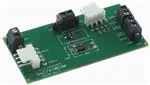
Figure 1. bq27410EVM Layout – Silk Screen
Figure 2. bq27410EVM Layout – Top Assembly
4
bq27410EVM: Single-Cell Impedance Track™ Technology
SLUU482A – February 2011 – Revised August 2011
Submit Documentation Feedback
Copyright © 2011, Texas Instruments Incorporated
�Circuits Module Physical Layout and Bill of Material
www.ti.com
Figure 3. bq27410EVM Layout – Top Layer
Figure 4. bq27410EVM Layout – Bottom Layer
4.2
Bill of Materials
Table 2. Bill of Materials
Coun RefDes
t
Value
Description
Size
Part Number
Mfr
3
C1, C2, C4
0.1 µF
Capacitor, Ceramic, 0.1 µF, 10V, X5R
0402
GRM155R61A104KA01D
Murata
1
C3
0.47 µF
Capacitor, Ceramic, 0.47 µF, 6.3V, X5R
0402
GRM155R60J474KE19D
Murata
1
D1
AZ23C5V6-7
Diode, Dual, Zener, 5.6 V, 300mW
SOT23
AZ23C5V6-7
Diodes
2
J1, J3
22-05-3041
Header, Friction Lock Ass'y, 4-pin Right Angle
0.400 x 0.500
22-05-3041
Molex
4
J2, J4, J5, J6
ED555/2DS
Terminal Block, 2-pin, 6-A, 3.5mm
0.27 x 0.25 inch
ED555/2DS
OST
1
R2
0.01
Resistor, Chip, 1/10W, 1%,
很抱歉,暂时无法提供与“BQ27410EVM”相匹配的价格&库存,您可以联系我们找货
免费人工找货- 国内价格
- 1+1930.07880
- 200+770.11560
- 500+744.37920
- 1000+731.66760