SWRU290B
December 2015
CC1120 Development Kit Quick Start Guide
Opening the Box and Running the Packet Error Rate Test
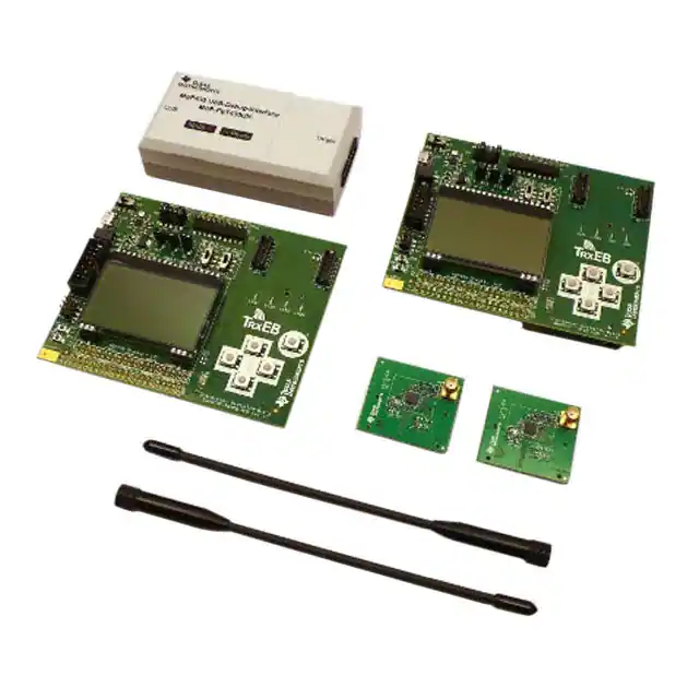
1. Kit Contents
2. TrxEB Overview
Power
Selection
EM
Breakout
3. Plug the EM into the TrxEB
Board Mode
Switches
EM
Connectors
Main
Power
Switch
USB
2 x SmartRF™ Transciever EB (TrxEB)
2 x CC1120EM 868/915 MHz (EM)
2 x W5017 Pulse Antennas, ¼ wave, 2 dBi *
1 x MSP430 Debug Probe (FET)
MSP430
2 x Micro USB Cables
Debug
1 x Standard USB Cable
Interface
1 x 14-pin Flat Cable
Documentation
Insert a CC1120EM board into the TrxEB as
shown above. Connect the antenna firmly to the
SMA connector on the EM.
MSP430
Breakout
LCD
Buttons
LEDs
Caution! The kit contains ESD
sensitive components. Handle with
care to prevent permanent damage.
The boards in this kit are designed to comply
with applicable ETSI, FCC and IC regulatory
requirements.
(* picture may deviate)
4. Select Board Mode
5. Power Options
Use the switches S1 and S2 to select the
operating mode of the board. For the sake of this
quick start guide, please select “Enable” and
“UART”. This configuration will make it possible
to communicate directly with the MSP430 over a
virtual COM port on the PC.
There are several ways of applying power to the
TrxEB.
6. Select Power Source
2 x 1.5V AA Non-Rechargeable Alkaline
Batteries
USB (5V through USB plug)
External Power Supply (requirements below)
MSP430 Debugger
When the power source is batteries or USB, the
voltage regulators on the TrxEB will set the onboard supply voltage to 3.3VDC.
i
External Power Supply Requirements:
Nom Voltage: 3.3VDC
Max Current: 800 mA
Efficiency Level V
Warning! To minimize risk of personal injury or
property damage, never use rechargeable
batteries to power the board.
Depending on the power source, make sure you
connect jumpers to the appropriate pins on the
“Power Source” header. For instance, if you use
batteries, use a jumper to short-circuit pin 1 and
2 on the header. See back side of board for
explanation of the jumpers.
Note that there should only be one active
power source at any one time. Do not leave
the EVM powered when unattended.
7. Welcome Screen
8. Packet Error Rate Test
9. Select Test Mode
Turn on power with the Main Power switch. You
should now see the Texas Instruments logo and
a short description of the buttons on the LCD.
Pushing any of the five buttons on the board will
take you to the main menu.
Select the PER (Packet Error Rate) test by
highlighting the selection using the up/down
buttons. Confirm your selection by pressing
Enter (right button).
The PER test can be run is several modes. Easy
Mode sets up a one-way test and uses default
settings. This test is convenient for practical
range testing.
The other test modes are described in the
“Software Examples for CC112x, CC11xL and
CC1101 User’s Guide”.
NB! If you don’t see anything on the screen
make sure the mode switches are in the
correct positions (see step 4 above).
To proceed, highlight “Easy Mode” and press
Enter (right button).
Web sites:
E2E Forum:
www.ti.com/lprf
www.ti.com/lprf-forum
Make sure to subscribe to the Low-Power RF
Newsletter to receive information about updates to
documentation, new product releases, and more.
Sign up on the TI web pages.
�10. Select Frequency
11. Select Mode
12. Establish Link
One of the boards must operate as the slave
(transmitter) and the other as master (receiver).
Select Slave on one board…
The slave node will now wait for a configuration
package from the Master. The configuration
contains the parameters used for the PER test.
…and Master on the other board.
The configuration package will be sent when you
select “link devices” on the master node.
13. Link Established
14. Start the Receiver (master)
15. PER Test Results
When the initial linking has completed, the slave
node will start the test by continuously
transmitting packets to the master.
On the master node, you can select the number
of packets you want to receive in order to
calculate the packet error.
The master will display a window that plots the
received signal strength (RSSI) for each packet.
When selecting “Start PER Test”, the master
(receiver) will begin to count the number of
received packets and provide some statistics.
Press the “Up” button to go to the detailed
statistical window.
17. Troubleshooting
18. References
It you are experiencing problems with this test,
please check the following:
Please visit www.ti.com and
http://www.ti.com/tool/cc1120dk
Select which frequency to use for the test. Make
sure that the evaluation modules you have
match the selected frequency.
16. PER Test Results
The statistics window will show the error rate
based on the number of lost or erroneous
packets divided by the total number of packets
that should have been received.
Nothing is shown in the display! Make sure
the mode switches are in the correct
positions (see step 4 above).
Please visit the kit web page and check for
updated SW and documentation. Updated
SW can be downloaded to the device using
IAR EW430 or SmartRF Flash Programmer.
If you get poor PER results at short
distances, try to move the transmitter and
receiver further apart. The CC1120 receiver
may experience saturation if it is too close to
the other CC1120 transmitting at full output
power.
On the kit product page, you will find additional
documentation, links to updated software
examples and software tools like SmartRF
Studio.
You will also find a lot of information on the TI
E2E forum at http://e2e.ti.com
We hope that you will enjoy working with the
CC1120 device.
SmartRF™ Studio
1. Download and Install
2. Launch SmartRF Studio
3. Test the Radio
Before connecting SmartRF TrxEB to your PC,
download and install SmartRF Studio from
www.ti.com/smartrfstudio.
After installing the tool, connect the EB to the PC
using the USB cable and start SmartRF Studio.
Select the “Sub 1 GHz” tab and double click the
highlighted CC1120 device icon.
You can now configure the radio, run
performance tests, export register settings and
run link tests with another CC1120 on a
SmartRF TrxEB connected to the PC.
i
When using an external power supply, make sure it meets the listed requirements in addition to complying with applicable regional product regulatory and
safety certification requirements such as UL, CSA, VDE, CCC, and PSE.
�IMPORTANT NOTICE FOR TI DESIGN INFORMATION AND RESOURCES
Texas Instruments Incorporated (‘TI”) technical, application or other design advice, services or information, including, but not limited to,
reference designs and materials relating to evaluation modules, (collectively, “TI Resources”) are intended to assist designers who are
developing applications that incorporate TI products; by downloading, accessing or using any particular TI Resource in any way, you
(individually or, if you are acting on behalf of a company, your company) agree to use it solely for this purpose and subject to the terms of
this Notice.
TI’s provision of TI Resources does not expand or otherwise alter TI’s applicable published warranties or warranty disclaimers for TI
products, and no additional obligations or liabilities arise from TI providing such TI Resources. TI reserves the right to make corrections,
enhancements, improvements and other changes to its TI Resources.
You understand and agree that you remain responsible for using your independent analysis, evaluation and judgment in designing your
applications and that you have full and exclusive responsibility to assure the safety of your applications and compliance of your applications
(and of all TI products used in or for your applications) with all applicable regulations, laws and other applicable requirements. You
represent that, with respect to your applications, you have all the necessary expertise to create and implement safeguards that (1)
anticipate dangerous consequences of failures, (2) monitor failures and their consequences, and (3) lessen the likelihood of failures that
might cause harm and take appropriate actions. You agree that prior to using or distributing any applications that include TI products, you
will thoroughly test such applications and the functionality of such TI products as used in such applications. TI has not conducted any
testing other than that specifically described in the published documentation for a particular TI Resource.
You are authorized to use, copy and modify any individual TI Resource only in connection with the development of applications that include
the TI product(s) identified in such TI Resource. NO OTHER LICENSE, EXPRESS OR IMPLIED, BY ESTOPPEL OR OTHERWISE TO
ANY OTHER TI INTELLECTUAL PROPERTY RIGHT, AND NO LICENSE TO ANY TECHNOLOGY OR INTELLECTUAL PROPERTY
RIGHT OF TI OR ANY THIRD PARTY IS GRANTED HEREIN, including but not limited to any patent right, copyright, mask work right, or
other intellectual property right relating to any combination, machine, or process in which TI products or services are used. Information
regarding or referencing third-party products or services does not constitute a license to use such products or services, or a warranty or
endorsement thereof. Use of TI Resources may require a license from a third party under the patents or other intellectual property of the
third party, or a license from TI under the patents or other intellectual property of TI.
TI RESOURCES ARE PROVIDED “AS IS” AND WITH ALL FAULTS. TI DISCLAIMS ALL OTHER WARRANTIES OR
REPRESENTATIONS, EXPRESS OR IMPLIED, REGARDING TI RESOURCES OR USE THEREOF, INCLUDING BUT NOT LIMITED TO
ACCURACY OR COMPLETENESS, TITLE, ANY EPIDEMIC FAILURE WARRANTY AND ANY IMPLIED WARRANTIES OF
MERCHANTABILITY, FITNESS FOR A PARTICULAR PURPOSE, AND NON-INFRINGEMENT OF ANY THIRD PARTY INTELLECTUAL
PROPERTY RIGHTS.
TI SHALL NOT BE LIABLE FOR AND SHALL NOT DEFEND OR INDEMNIFY YOU AGAINST ANY CLAIM, INCLUDING BUT NOT
LIMITED TO ANY INFRINGEMENT CLAIM THAT RELATES TO OR IS BASED ON ANY COMBINATION OF PRODUCTS EVEN IF
DESCRIBED IN TI RESOURCES OR OTHERWISE. IN NO EVENT SHALL TI BE LIABLE FOR ANY ACTUAL, DIRECT, SPECIAL,
COLLATERAL, INDIRECT, PUNITIVE, INCIDENTAL, CONSEQUENTIAL OR EXEMPLARY DAMAGES IN CONNECTION WITH OR
ARISING OUT OF TI RESOURCES OR USE THEREOF, AND REGARDLESS OF WHETHER TI HAS BEEN ADVISED OF THE
POSSIBILITY OF SUCH DAMAGES.
You agree to fully indemnify TI and its representatives against any damages, costs, losses, and/or liabilities arising out of your noncompliance with the terms and provisions of this Notice.
This Notice applies to TI Resources. Additional terms apply to the use and purchase of certain types of materials, TI products and services.
These include; without limitation, TI’s standard terms for semiconductor products http://www.ti.com/sc/docs/stdterms.htm), evaluation
modules, and samples (http://www.ti.com/sc/docs/sampterms.htm).
Mailing Address: Texas Instruments, Post Office Box 655303, Dallas, Texas 75265
Copyright © 2018, Texas Instruments Incorporated
�


 工商网监
湘ICP备2023018690号
工商网监
湘ICP备2023018690号
