User's Guide
SWRU463C – February 2017 – Revised March 2020
CC3220 SimpleLink™ Wi-Fi® LaunchPad™ Development
Kit Hardware
The CC3220 device is part of the SimpleLink™ microcontroller (MCU) platform which consists of Wi-Fi®,
Bluetooth® low energy, Sub-1 GHz, and host MCUs. All share a common, easy-to-use development
environment with a single core software development kit (SDK) and rich tool set. A one-time integration of
the SimpleLink platform lets you add any combination of devices from the portfolio into your design. The
ultimate goal of the SimpleLink platform is to achieve 100 percent code reuse when your design
requirements change. For more information, visit www.ti.com/simplelink.
The CC3220 SimpleLink LaunchPad™ development kit (CC3220-LAUNCHXL) is a low-cost evaluation
platform for Arm® Cortex®-M4-based MCUs. The LaunchPad kit design highlights the CC3220 Internet-ona chip™ solution and Wi-Fi capabilities. The CC3220 LaunchPad kit also features temperature and
accelerometer sensors, programmable user buttons, three LEDs for custom applications, and onboard
emulation for debugging. The stackable headers of the CC3220 LaunchPad XL interface demonstrate how
easy it is to expand the functionality of the LaunchPad kit when interfacing with other peripherals on many
existing BoosterPack™ plug-in module add-on boards, such as graphical displays, audio codecs, antenna
selection, environmental sensing, and more.
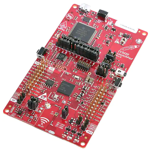
Figure 1 shows the CC3220 LaunchPad development kit.
Figure 1. CC3220 SimpleLink Wi-Fi LaunchPad Development Kit
SWRU463C – February 2017 – Revised March 2020
Submit Documentation Feedback
CC3220 SimpleLink™ Wi-Fi® LaunchPad™ Development Kit Hardware
Copyright © 2017–2020, Texas Instruments Incorporated
1
�www.ti.com
1
2
3
4
Contents
Introduction ................................................................................................................... 4
1.1
CC3220 LaunchPad Development Kit ........................................................................... 4
1.2
Key Features ....................................................................................................... 5
1.3
What's Included .................................................................................................... 5
1.4
Regulatory Compliance ............................................................................................ 5
1.5
First Steps: Out-of-Box Experience .............................................................................. 5
1.6
Next Steps: Looking into the Provided Code.................................................................... 6
Hardware Description ....................................................................................................... 7
2.1
Block Diagram ...................................................................................................... 8
2.2
Hardware Features ................................................................................................. 8
2.3
Connecting a BoosterPack Plug-in Module ..................................................................... 9
2.4
XDS110-Based JTAG Emulator ................................................................................ 10
2.5
Wired Connections, Jumper Settings, Buttons, and LEDs ................................................... 10
2.6
Power ............................................................................................................... 20
2.7
Isolated Current Measurement of the CC3220 ............................................................... 23
2.8
RF Connections ................................................................................................... 25
2.9
Assembly Drawing ................................................................................................ 26
2.10 Design Files ........................................................................................................ 27
2.11 Software ............................................................................................................ 27
Development Environment Requirements .............................................................................. 27
3.1
CCS IDE ............................................................................................................ 27
3.2
IAR IDE ............................................................................................................. 27
Additional Resources ...................................................................................................... 27
4.1
CC3220 Product Page ............................................................................................ 27
4.2
LaunchPad Development Kit Wiki............................................................................... 27
4.3
Download a Development Environment ........................................................................ 28
4.4
SimpleLink™ Academy for CC3220 SDK ..................................................................... 28
4.5
Support Resources ................................................................................................ 28
List of Figures
1
2
3
4
5
6
7
8
9
10
11
12
13
14
15
16
17
18
19
20
21
2
.............................................................. 1
WEEE Statement ............................................................................................................ 4
CC3220 LaunchPad Development Kit Overview ........................................................................ 7
CC3220 Block Diagram ..................................................................................................... 8
Pin 1 Marking on CC3220LP (3V3 Tag) .................................................................................. 9
XDS-110 Debug Probe ................................................................................................... 10
Default Jumper Configuration for JTAG Lines.......................................................................... 10
JTAG IN Connector (J8)................................................................................................... 11
XDS110 OUT Connector (J4) ............................................................................................ 12
I2C Bus Connections ....................................................................................................... 13
Power Jumpers J14, J21, J20, J19, J17, and J18 ..................................................................... 14
SOP Jumpers (Default Setting Shown) ................................................................................. 16
UART Routed to USB COM Port......................................................................................... 17
UART Routed to 20-Pin Header Connector ............................................................................ 17
CC3220 BoosterPack Module Header Pin Assignments ............................................................. 19
Powering From USB Jumper Settings ................................................................................... 20
Powering the CC3220LP From Battery ................................................................................. 21
Only CC3220 and Serial Flash Powered by Battery................................................................... 22
Low-Current Measurement (1 mA) ................................................................................... 24
Using Onboard Antenna (Default Condition) ........................................................................... 25
CC3220 SimpleLink Wi-Fi LaunchPad Development Kit
CC3220 SimpleLink™ Wi-Fi® LaunchPad™ Development Kit Hardware
SWRU463C – February 2017 – Revised March 2020
Submit Documentation Feedback
Copyright © 2017–2020, Texas Instruments Incorporated
�www.ti.com
22
Board Modified for External Antenna Connections .................................................................... 25
23
CC3220x LaunchPad Kit Top-Layer Assembly Drawing .............................................................. 26
24
CC3220 SimpleLink Academy ............................................................................................ 28
List of Tables
1
JTAG Header Pin Definitions ............................................................................................. 11
2
I2C Jumper Definitions ..................................................................................................... 13
3
Default I2C Addresses (of Onboard Sensors)
4
5
6
7
8
9
..........................................................................
Jumper Settings for LaunchPad Kit Power .............................................................................
External Supply Connections and LED Enable Jumper...............................................................
Reset Pullup Jumper.......................................................................................................
SOP[2:0] (J13 on LaunchPad Kit)........................................................................................
Push-Button Definitions ...................................................................................................
LED Indicators ..............................................................................................................
14
15
15
15
16
18
18
Trademarks
SimpleLink, LaunchPad, Internet-on-a chip, BoosterPack, Code Composer Studio, Tiva, E2E are
trademarks of Texas Instruments.
Arm, Cortex are registered trademarks of Arm Limited.
Bluetooth is a registered trademark of Bluetooth SIG.
IAR Embedded Workbench is a registered trademark of IAR Systems AB.
Wi-Fi is a registered trademark of Wi-Fi Alliance.
All other trademarks are the property of their respective owners.
SWRU463C – February 2017 – Revised March 2020
Submit Documentation Feedback
CC3220 SimpleLink™ Wi-Fi® LaunchPad™ Development Kit Hardware
Copyright © 2017–2020, Texas Instruments Incorporated
3
�Introduction
www.ti.com
1
Introduction
1.1
CC3220 LaunchPad Development Kit
Created for the Internet of Things (IoT), the SimpleLink Wi-Fi CC3220 device is a single-chip
microcontroller (MCU) with built-in Wi-Fi connectivity for the LaunchPad ecosystem, which integrates a
high-performance Arm Cortex-M4 MCU and lets customers develop an entire application with one device.
With on-chip Wi-Fi, Internet, and robust security protocols, no prior Wi-Fi experience is required for fast
development.
The CC3220 LaunchPad kit, referred to by its part number CC3220-LAUNCHXL, is a low-cost evaluation
platform for Arm Cortex-M4-based MCUs. The LaunchPad kit design highlights the CC3220 Internet-on-a
chip solution and Wi-Fi capabilities. The CC3220 LaunchPad kit also features temperature and
accelerometer sensors, programmable user buttons, three LEDs for custom applications, and onboard
emulation for debugging. The stackable headers of the CC3220 LaunchPad XL interface demonstrate how
easy it is to expand the functionality of the LaunchPad kit when interfacing with other peripherals on many
existing BoosterPack add-on boards, such as graphical displays, audio codecs, antenna selection,
environmental sensing, and more. Figure 3 shows the CC3220 LaunchPad kit. There are two variants of
the LaunchPad kit: the CC3220S-LAUNCHXL and the CC3220SF-LAUNCHXL. This user's guide applies
to both variants, and any differences are pointed out in relevant sections.
Multiple development environment tools are also available, including TI’s Eclipse-based Code Composer
Studio™ (CCS) integrated development environment (IDE) and IAR Embedded Workbench®. More
information about the LaunchPad kit, the supported BoosterPack modules, and the available resources
can be found at TI’s LaunchPad portal. Also visit the CC3220 Wiki page for design resources and example
projects.
NOTE: The maximum RF power transmitted in each WLAN 2.4-GHz band is 17.5 dBM (EIRP
power).
NOTE: The antennas used for this transmitter must be installed to provide a separation distance of
at least 20 cm from all persons, and must not be colocated or operating in conjunction with
any other antenna or transmitter.
NOTE: All figures and references in this document apply to RevA and RevB. Most of the document
also applies to higher revisions, unless otherwise stated.
Figure 2. WEEE Statement
4
CC3220 SimpleLink™ Wi-Fi® LaunchPad™ Development Kit Hardware
SWRU463C – February 2017 – Revised March 2020
Submit Documentation Feedback
Copyright © 2017–2020, Texas Instruments Incorporated
�Introduction
www.ti.com
1.2
Key Features
•
•
•
•
•
•
•
•
1.3
What's Included
1.3.1
Kit Contents
•
•
•
1.3.2
CC3220 LaunchPad development tool (CC3220S-LAUNCHXL or CC3220SF-LAUNCHXL)
Micro USB cable
Quick start guide
Software Examples
•
1.4
CC3220S/SF, SimpleLink Wi-Fi, Internet-on-a chip solution with integrated MCU
40-pin LaunchPad standard that leverages the BoosterPack ecosystem
XDS110-based JTAG emulation with serial port for flash programming
Two buttons and three LEDs for user interaction
Back-channel universal asynchronous receiver/transmitter (UART) through USB to PC
Onboard chip antenna with U.FL for conducted testing
Onboard accelerometer and temperature sensor for Out-of-Box Experience (OOBE)
Micro USB connector for power and debug connections
Out-of-Box Software
Regulatory Compliance
The SimpleLink CC3220 Wi-Fi LaunchPad kit is tested for and found to be in compliance with FCC and
ISED regulations regarding unlicensed intentional radiators.
Hereby, Texas Instruments Inc. declares that the radio equipment type CC3220S-LAUNCHXL and
CC3220SF-LAUNCHXL are in compliance with Directive 2014/53/EU. The full text of the EU declaration of
conformity is available at the following internet addresses:
• CC3220S-LAUNCHXL
• CC3220SF-LAUNCHXL
1.5
First Steps: Out-of-Box Experience
An easy way to get started with the EVM is by using its preprogrammed out-of-box code. It demonstrates
some key features of the EVM.
1.5.1
Connecting to the Computer
Connect the LaunchPad development kit by connecting the included USB cable to a computer. A red
power LED should illuminate. For proper operation, the SimpleLink drivers and Service Pack from the
CC3220 Software Development Kit (SDK) are needed. The SDK is available at
www.ti.com/tool/SIMPLELINK-CC3220-SDK.
SWRU463C – February 2017 – Revised March 2020
Submit Documentation Feedback
CC3220 SimpleLink™ Wi-Fi® LaunchPad™ Development Kit Hardware
Copyright © 2017–2020, Texas Instruments Incorporated
5
�Introduction
1.5.2
www.ti.com
Running the Out-of-Box Experience
The CC3220 LaunchPad development kit's Out-of-Box Experience (OOBE) demonstrates and highlights
the following features:
• Easy connection to the CC3220 LaunchPad kit:
– Using the SimpleLink Wi-Fi Starter Pro application (available on iOS and Android™), users can use
Access Point (AP) provisioning or SmartConfig™ provisioning for a fast CC3220 connection.
– Configuring the device in AP mode gives users a direct connection to the CC3220 LaunchPad kit.
Once the device is provisioned and connected to an AP in station mode, the profile is stored on the
local file system so that any reset to the CC3220 automatically connects it to the AP.
• Easy access to the CC3220 through its internal web server, using either:
– The SimpleLink Wi-Fi Starter Pro application
– Any browser; web pages stored on the serial flash are loaded on the browser, to provide ease of
use.
This feature demonstrates configuring and reading onboard sensors.
• Over-The-Air (OTA) updates that demonstrate an update of a full image. OTA service enables insystem updates of the MCU application, CC3220 firmware releases (Service Pack) made available by
TI, and other vendor files. An update procedure executed in a full-system integrity fashion, such as
failure to upgrade any image components, results in rolling back to the previous valid version.
See the CC3220 LaunchPad Out-of-Box User's Guide for more details on the Out-of-Box Experience.
1.6
Next Steps: Looking into the Provided Code
After the EVM features have been explored, the user can open an integrated development environment
and start editing the code examples from the SDK. See Section 4.3 for available IDEs and where to
download them. The Out-of-Box source code and more code examples are provided in the CC3220 SDK.
Code is licensed under BSD, and TI encourages reuse and modifications to fit specific needs.
With the onboard XDS110 debug probe, debugging and downloading new code is simple. A USB
connection between the EVM and a PC through the provided USB cable is all that is needed.
6
CC3220 SimpleLink™ Wi-Fi® LaunchPad™ Development Kit Hardware
SWRU463C – February 2017 – Revised March 2020
Submit Documentation Feedback
Copyright © 2017–2020, Texas Instruments Incorporated
�Hardware Description
www.ti.com
2
Hardware Description
Figure 3 shows the CC3220 LaunchPad kit.
Figure 3. CC3220 LaunchPad Development Kit Overview
SWRU463C – February 2017 – Revised March 2020
Submit Documentation Feedback
CC3220 SimpleLink™ Wi-Fi® LaunchPad™ Development Kit Hardware
Copyright © 2017–2020, Texas Instruments Incorporated
7
�Hardware Description
2.1
www.ti.com
Block Diagram
Figure 4 shows the CC3220 block diagram.
U. FL
Filter
USB
Conn
Acceleration
Sensor
BMA222
5V
INT (GPIO13)
I2C
JTAG/SWD
XDS110 JTAG
Debug Probe
UART (Flashing/Log)
S-Flash
32Mbit
40-MHz XTAL
5V
CC3220
32.768-kHz XTAL
VCC
3.3-V LDO
2× AA Battery
Conn
Temp Sensor
TMP006
Reverse
Protection
Push Buttons
LEDs
GPIO 13, 22 GPIO 9,10,11
2× 20 Launchpad Headers
(Compatible with TI MCU Std)
Copyright © 2017, Texas Instruments Incorporated
Figure 4. CC3220 Block Diagram
2.2
Hardware Features
•
•
•
•
•
•
•
•
•
•
•
•
•
8
CC3220S/SF, SimpleLink Wi-Fi, Internet-on-a chip solution with integrated MCU
40-pin LaunchPad standard that leverages the BoosterPack ecosystem
TI Standard XDS110-based JTAG emulation with serial port for flash programming
Supports both 4-wire JTAG and 2-wire SWD
Two buttons and three LEDs for user interaction
Back-channel universal asynchronous receiver/transmitter (UART) through USB to PC
Onboard chip antenna with U.FL for conducted testing selectable using 0-Ω resistors
Onboard accelerometer and temperature sensor for Out-of-Box Experience, with option to isolate them
from the inter-integrated circuit (I2C) bus
Micro USB connector for power and debug connections
Headers for current measurement and external JTAG connection with an option to use the onboard
XDS110 to debug customer platforms
Bus-powered device, with no external power required for Wi-Fi
Long-range transmission with a highly optimized antenna (200-meter typical in open air with a 6-dBi
antenna AP)
Can be powered externally, working down to 2.3 V (typical)
CC3220 SimpleLink™ Wi-Fi® LaunchPad™ Development Kit Hardware
SWRU463C – February 2017 – Revised March 2020
Submit Documentation Feedback
Copyright © 2017–2020, Texas Instruments Incorporated
�Hardware Description
www.ti.com
2.3
Connecting a BoosterPack Plug-in Module
A compatible BoosterPack module can be stacked on top of the LaunchPad kit using the 2-pin × 20-pin
connectors. The connectors do not have a key to prevent the misalignment of the pins or reverse
connection.
Ensure that the VCC and 5-V pins are aligned with the BoosterPack module header pins. On the CC3220
LaunchPad kit, a small white 3V3 tag symbol is provided near pin 1 (see Figure 5) to orient all
BoosterPack modules. This same marking, provided on compatible BoosterPack modules, must be
aligned before powering up the boards.
Figure 5. Pin 1 Marking on CC3220LP (3V3 Tag)
SWRU463C – February 2017 – Revised March 2020
Submit Documentation Feedback
CC3220 SimpleLink™ Wi-Fi® LaunchPad™ Development Kit Hardware
Copyright © 2017–2020, Texas Instruments Incorporated
9
�Hardware Description
2.4
www.ti.com
XDS110-Based JTAG Emulator
To keep development easy and cost effective, TI's LaunchPad development kits integrate an onboard
debug probe, which eliminates the need for expensive programmers. The CC3220 LaunchPad kit has the
XDS-110-based debug probe (see Figure 6), which is a simple and low-cost debugger that supports
nearly all TI Arm device derivatives.
Figure 6. XDS-110 Debug Probe
2.5
2.5.1
Wired Connections, Jumper Settings, Buttons, and LEDs
JTAG Headers
The headers are provided on the board to isolate the CC3220 device from the onboard XDS110-based
JTAG emulator. These jumpers are shorted by default when the board is shipped from TI. Figure 7 and
Table 1 are for default configurations, and Figure 8 shows the external emulator connection.
Figure 7. Default Jumper Configuration for JTAG Lines
10
CC3220 SimpleLink™ Wi-Fi® LaunchPad™ Development Kit Hardware
SWRU463C – February 2017 – Revised March 2020
Submit Documentation Feedback
Copyright © 2017–2020, Texas Instruments Incorporated
�Hardware Description
www.ti.com
Table 1. JTAG Header Pin Definitions
Reference (Rev.
A/C)
Reference (Rev. B) (1)
J3 (TCK) (2)
J8 (TCK)
JTAG / SWD
(2)
J3 (TMS)
Use
J8 (TMS)
JTAG / SWD
J3 (TDI)
J8 (TDI)
JTAG
J3(TDO)
J8 (TDO)
JTAG
(1)
(2)
Comments
Jumpers populated: onboard emulator connected
Jumpers not populated: onboard emulator disconnected
The only difference between Rev. A and Rev. B are the reference designators on the board.
For SWD mode, the TCK and TMS headers must be shorted.
To connect an external emulator, remove these jumpers and place the external emulator on the JTAG IN
connector.
Figure 8. JTAG IN Connector (J8)
SWRU463C – February 2017 – Revised March 2020
Submit Documentation Feedback
CC3220 SimpleLink™ Wi-Fi® LaunchPad™ Development Kit Hardware
Copyright © 2017–2020, Texas Instruments Incorporated
11
�Hardware Description
2.5.2
www.ti.com
Using the XDS110 Debug Probe With a Different Target
The XDS110 debug probe on the LaunchPad development kit can interface to most Arm Cortex-M
devices, not just the onboard target CC3220 device. This functionality is enabled by the J4 10-pin CortexM JTAG connector (See Figure 9) and a 10-pin cable, such as the FFSD-05-D-06.00-01-N (sold
separately from the LaunchPad development kit).
Figure 9. XDS110 OUT Connector (J4)
Header J4 follows the Cortex-M Arm standard; however, pin 1 is not a voltage sense pin. The XDS110
outputs only 3.3-V JTAG signals. If another voltage level is needed, the user must provide level shifters to
translate the JTAG signal voltages.
1. Remove jumpers on the JTAG signals on the isolation block, including RST, TMS, TCK, TDO, and TDI.
2. Plug the 10-pin cable into J4, and connect to an external target.
a. J4 follows the Arm Cortex Debug Connector standard outlined in Cortex-M Debug Connectors.
3. Plug USB power into the LaunchPad development kit, or power it externally.
a. JTAG levels are 3.3-V ONLY
12
CC3220 SimpleLink™ Wi-Fi® LaunchPad™ Development Kit Hardware
SWRU463C – February 2017 – Revised March 2020
Submit Documentation Feedback
Copyright © 2017–2020, Texas Instruments Incorporated
�Hardware Description
www.ti.com
2.5.3
I2C Connections
The board features an accelerometer and a temperature sensor for the out-of-box demo. These are
connected to the I2C bus, and can be isolated using the jumpers provided (shown as yellow jumpers J15
and J16 in Figure 10).
Figure 10. I2C Bus Connections
By removing J15 and J16, the accelerometer and the temperature sensors are isolated from the I2C bus.
This measure also removes the I2C pullup resistors from the sensor side of the circuit, and therefore any
connection to the circuit requires the user to install external pullup resistors.
Table 2 lists the I2C jumper definitions.
Table 2. I2C Jumper Definitions
Reference (Rev.
A/C)
Reference (Rev. B)
J16
J2
Use
I2C SDA
Comments
Populated: CC3220 SDA connected to onboard sensors with
pullup
Open: CC3220 SDA disconnected from onboard sensors
J15
I2C SCL
J3
Populated: CC3220 SCL connected to onboard sensors with
pullup
Open: CC3220 SCL disconnected from onboard sensors
SWRU463C – February 2017 – Revised March 2020
Submit Documentation Feedback
CC3220 SimpleLink™ Wi-Fi® LaunchPad™ Development Kit Hardware
Copyright © 2017–2020, Texas Instruments Incorporated
13
�Hardware Description
www.ti.com
Default I2C Addresses
2.5.3.1
Table 3 lists the default I2C addresses of the onboard sensors.
Table 3. Default I2C Addresses (of Onboard Sensors)
Reference Designator
on LP (Rev. A/C)
Reference Designator
on LP (Rev. B)
Part Number
(Manufacturer)
Default Slave
Address (Hex)
Temperature (MEMS
IR Thermopile)
U10
U6
TMP116 (1) (TI)
0x49
Accelerometer
(Triaxial)
U11
U10
BMA222E (Bosch)
0x18
Sensor Type
(1)
2.5.4
The TMP116 on Rev. C LaunchPad kits replaced the TMP006 (slave address: 0x41) on Rev. A and B.
Power Connections
The board can be powered by using the onboard micro USB connector. An onboard DC-DC converter
provides 3.3 V for the CC3220 and the rest of the board to operate. This supply can be isolated from the
DC-DC using the jumpers on the board. See the yellow jumpers in Figure 11.
Figure 11. Power Jumpers J14, J21, J20, J19, J17, and J18
NOTE: The blue jumpers in Figure 11 are previously discussed (see Section 2.5.1) and are
populated by default. Figure 11 does not show unpopulated jumpers (which would be
populated normally).
14
CC3220 SimpleLink™ Wi-Fi® LaunchPad™ Development Kit Hardware
SWRU463C – February 2017 – Revised March 2020
Submit Documentation Feedback
Copyright © 2017–2020, Texas Instruments Incorporated
�Hardware Description
www.ti.com
Table 4 lists the jumper settings for the LaunchPad kit power.
Table 4. Jumper Settings for LaunchPad Kit Power
Reference
(Rev. A)
Reference
(Rev. B)
Use
Comments
J14
J5
OPAMP EN
J21
J10
GND
J20
J29
+5 VDC power
jumper
J19
J12
J17
J13
Board power
J18
J28
VSENSE
If the jumper is uninstalled, the power supply to the OPAMP is cut off. This
can be used to enable low-current measurements. Ensure that this jumper
is on to use the OPAMP to drive the input to the ADC. The reference
voltage of the ADC is 1.47 V, so up to 3.48 V can be applied to the input of
the OPAMP. For the configuration of the OPAMP, see the CC3220
LaunchPad Kit Design Files.
Ground reference
Connects J19, +5 VDC to emulator section
Current measurement Measures the current flowing into the CC3220 device and the serial flash.
Short: Supply the board power from the onboard DC-DC converter. The
board power includes the sensors, LED, and the OPAMP used to drive the
ADC input.
Used to power the level shifters on the emulator side of the board. The level
shifters can be powered by shorting this jumper. Removing this jumper
enables low-current measurement.
The board can be powered by an external supply when USB power is not available, by using either J22 or
J23. J24 is also available to remove any current draw from LEDs being driven by the GPIOs, see Table 5.
Table 5. External Supply Connections and LED Enable Jumper
2.5.5
Reference
(Rev. A/C)
Reference
(Rev. B)
Use
J19
J12
Alternative 3.3-V
power input
Can be used to power the board from an external 3.3-V supply; this can be
used to test the VBAT voltage range as the reverse voltage protection diode
on J22 drops the input by approximately 150 mV.
J23
J19
5-V power input
Used to power the board from an external 5-V supply.
J22
J20
3.3-V power input
J24
J9
LED EN
Comments
Used to power the board from an external 3.3-V supply. J22 has built-in
reverse voltage protection to prevent the battery from being plugged in the
reverse manner.
If uninstalled, the LEDs connected to the GPIO are disabled; this can be
used to enable low-power measurements.
Reset Pullup Jumper
Table 6 lists the reset pullup jumper.
Table 6. Reset Pullup Jumper
Reference
(Rev. A/C)
Reference
(Rev. B)
Use
J9
J26
RESET pullup
SWRU463C – February 2017 – Revised March 2020
Submit Documentation Feedback
Comments
Install this jumper to enable the pullup resistor on the nRESET pin of the
device, when the board is powered from an external supply.
CC3220 SimpleLink™ Wi-Fi® LaunchPad™ Development Kit Hardware
Copyright © 2017–2020, Texas Instruments Incorporated
15
�Hardware Description
2.5.6
www.ti.com
Sense on Power (SOP)
The CC3220 can be set to operate in four different modes, based on the state of the sense-on-power
(SOP) lines. These SOP lines are pins 21, 34, and 35 on the CC3220 device. Table 7 describes the state
of the device, and Figure 12 shows the SOP jumpers.
Table 7. SOP[2:0] (J13 on LaunchPad Kit)
Binary
Value
Function
000
Functional mode and 4-wire JTAG
001
Functional mode and 2-wire JTAG
010
Functional mode and flash programming
011
Factory default
100
Flash programming
Figure 12. SOP Jumpers (Default Setting Shown)
NOTE: SOP[2:0] corresponds to J13 in the LaunchPad kit schematic design.
NOTE: No jumpers on the block ensure that the line is pulled low using 100-kΩ pulldown resistors.
Placing the jumper pulls the pin high using a 270-Ω resistor.
16
CC3220 SimpleLink™ Wi-Fi® LaunchPad™ Development Kit Hardware
SWRU463C – February 2017 – Revised March 2020
Submit Documentation Feedback
Copyright © 2017–2020, Texas Instruments Incorporated
�Hardware Description
www.ti.com
2.5.7
UART Signals
The board supports a USB-based virtual COM port, using the Tiva™ Arm MCU. The LaunchPad kit is
shipped with the UART lines from the CC3220 connected to the UART on the Tiva MCU. The CC3220
UART TX can also be routed to the 20-pin connector for use as a GPIO or external UART. The selection
is performed using jumpers on the board. The RX signal cannot be routed to the 20 pin connector
because it is interfaced to an op-amp to use with an ADC. To use the pin as GPIO or external UART you
must use the second pin on the J6 column.
Figure 13 shows the UART routed to USB COM port and Figure 14 shows the UART routed to 20-pin
header connector.
Figure 13. UART Routed to USB COM Port
Figure 14. UART Routed to 20-Pin Header Connector
SWRU463C – February 2017 – Revised March 2020
Submit Documentation Feedback
CC3220 SimpleLink™ Wi-Fi® LaunchPad™ Development Kit Hardware
Copyright © 2017–2020, Texas Instruments Incorporated
17
�Hardware Description
2.5.8
www.ti.com
Push-Buttons and LED Indicators
Table 8 list the push-button definitions.
Table 8. Push-Button Definitions
Reference
(Rev. A/C)
Reference
(Rev. B)
Use
Comments
This is used to reset the CC3220 device. This signal is also output on the
20-pin connector to reset any external BoosterPack module which may be
stacked. The reset can be isolated using the jumper block at the center of
the board.
SW1
SW1
RESET
SW2
SW3
GPIO_13
When pushed, GPIO_13 is pulled to VCC.
SW3
SW2
GPIO_22
When pushed, GPIO_22 is pulled to VCC.
SW4
SW4
Factory default
Pressing this button and toggling RESET restores the factory default image
on the serial flash. This can be used to recover a corrupted serial flash,
provided the s-flash was programmed with a recovery image.
Table 9 lists the LED indicators.
Table 9. LED Indicators
(1)
18
Reference
(Rev. A/C)
Reference
(Rev. B)
Color
Use
D1, D2
D2, D9
Green and
Red
Debug
D3
D1
Yellow
nRESET
D6
D8
Red
D7
D4
Red
Power
D8
D5
Green
GPIO_11 (1)
On when the GPIO is logic-1.
(1)
On when the GPIO is logic-1.
D9
D6
Yellow
D10
D7
Red
Comments
Indicates the state of the JTAG emulator. For TI use only.
Indicates the state of the nRESET pin. If this LED is on, the device
is functional.
Factory Reset Indicates that the push-button for the factory reset is pressed.
GPIO_10
Indicates when the 3.3-V power is supplied to the board.
GPIO_09
On when the GPIO is logic-1.
GPIO_10 and GPIO_11 are also used as I2C. Thus, when the pullup resistors are enabled, the LEDs are on by default, without
configuring the GPIOs.
CC3220 SimpleLink™ Wi-Fi® LaunchPad™ Development Kit Hardware
SWRU463C – February 2017 – Revised March 2020
Submit Documentation Feedback
Copyright © 2017–2020, Texas Instruments Incorporated
�Hardware Description
www.ti.com
2.5.9
BoosterPack Module Header Pin Assignment
The TI BoosterPack module header pinout specification is at Build Your Own BoosterPack. Also see the BoosterPack Pinout Standard.
The CC3220 LaunchPad kit follows this standard, with the exception of naming. (P1:P4 is used instead of J1:J4.) See Figure 15 for CC3220 pinmapping assignments and functions.
J1
J2
+3.3 V
58
ANALOG_IN
4
UART_RX
3
UART_TX
GND
GPIO_03 *
GPIO_28
GPIO
GPIO_13
GPIO_17
SPI CS Wls.
8
GPIO_12
GPIO_31
GPIO
45
7
18
61
GPIO
GPIO_06
RST
59
ADC_CH2
GPIO_04 *
GPIO_16
MOSI
5
SPI_CLK
GPIO_14 *
GPIO_15
MISO
6
62
GPIO
GPIO_07
GPIO_25
MOSI
21
1
12C SCL
GPIO_10
GPIO_01
MISO
55
2
12C SDA
GPIO_11
GPIO_22
GPIO
15
CC3220
Wi-Fi
NWP
+5 V
OUT
PWM
GND
OUT
PWM
1
NA
PWM
17
2
57
ANALOG_IN
GPIO_02
60
ANALOG_IN
GPIO_05
IN
PWM
64
58
ANALOG_IN
GPIO_03
OUT
CCAP
21
59
ANALOG_IN
GPIO_04
NA
CCAP/GPIO
18
63
I2C WS
GPIO_08
OUT
GPIO
62
53
12S SCLK
GPIO_30
OUT
GPIO
60
64
I2S SDout
GPIO_09
IN
GPIO
16
50
12S SDin
GPIO_00
GPIO_24
GPIO
17
J3
J4
Copyright © 2017, Texas Instruments Incorporated
Figure 15. CC3220 BoosterPack Module Header Pin Assignments
NOTE: RESET output is an open-drain-type output and can only drive the pin low. The pullup ensures that the line is pulled back high when the
button is released. No external BoosterPack module can drive this pin low.
All the signals are referred to by the pin number in the SDK; Figure 15 shows the default mappings. Some of the pins are repeated across the
connector. For instance, pin 62 is available on P1 and P4, but only P1 is connected by default. The signal on P4 is marked with an asterisk (*) to
signify that it is not connected by default. The signal can be routed to the pin by using a 0-Ω resistor in the path. For the exact resistor placement,
see the CC3220 SimpleLink Wi-Fi Wireless MCU LaunchPad Board Design Files.
SWRU463C – February 2017 – Revised March 2020
Submit Documentation Feedback
CC3220 SimpleLink™ Wi-Fi® LaunchPad™ Development Kit Hardware
Copyright © 2017–2020, Texas Instruments Incorporated
19
�Hardware Description
2.6
2.6.1
www.ti.com
Power
USB Power
The LaunchPad kit is designed to work from the USB-provided power supply. The LaunchPad kit provides
addresses as a bus-powered device on the computer. To power the CC3220 device from the USB, the
jumpers must be placed on the following headers, as shown in Figure 16.
Figure 16. Powering From USB Jumper Settings
20
CC3220 SimpleLink™ Wi-Fi® LaunchPad™ Development Kit Hardware
SWRU463C – February 2017 – Revised March 2020
Submit Documentation Feedback
Copyright © 2017–2020, Texas Instruments Incorporated
�Hardware Description
www.ti.com
2.6.2
Battery Power
The LaunchPad kit can also be powered from an external battery pack by feeding the voltage on the J22
header. This input features reverse voltage protection to ensure that the board is not damaged due to an
accidental reverse voltage. Perform the following steps before using the board with a battery. The board
would appear as shown in Figure 17.
1. Remove the USB cable.
2. Plug in the battery pack on J22 with the correct polarity.
3. Ensure that a jumper is placed on RST_PU (J9) of the LaunchPad kit.
4. Connect a jumper across J17 and J19. This is done to supply board power from the battery.
Figure 17. Powering the CC3220LP From Battery
SWRU463C – February 2017 – Revised March 2020
Submit Documentation Feedback
CC3220 SimpleLink™ Wi-Fi® LaunchPad™ Development Kit Hardware
Copyright © 2017–2020, Texas Instruments Incorporated
21
�Hardware Description
2.6.3
www.ti.com
Battery Powering Only the CC3220 and U8 (Onboard Serial Flash)
In some cases, there may be a requirement to power only the CC3220 and the serial flash from the
battery. The usage may not require LEDs, OPAMP for the ADC, and the sensors. In this case, the other
sections can be powered off by removing the appropriate jumpers. Ensure that a jumper is placed on
RST_PU (J9) of the LaunchPad kit. The board would appear as shown in Figure 18.
Figure 18. Only CC3220 and Serial Flash Powered by Battery
22
CC3220 SimpleLink™ Wi-Fi® LaunchPad™ Development Kit Hardware
SWRU463C – February 2017 – Revised March 2020
Submit Documentation Feedback
Copyright © 2017–2020, Texas Instruments Incorporated
�Hardware Description
www.ti.com
2.7
Isolated Current Measurement of the CC3220
To measure the current draw of the CC3220 when powering with a USB cable, use the VBAT jumper on
the jumper isolation block (J19). The current measured in this mode includes only the CC3220 current and
the serial flash current, and no external blocks. However, if a GPIO of the CC3220 is driving a high-current
load such as an LED, then that is also included in this measurement.
2.7.1
Low-Current Measurement With USB Power (< 1 mA)
To measure the current draw of the CC3220 MCU and serial flash using a ammeter, use the VBAT jumper
on the isolation block. Follow these steps to measure ultra-low power operation of the CC3220:
1. Remove the VBAT jumper (J19) in the isolation block; attach an ammeter across this jumper, as shown
in Figure 19.
2. Consider the effect that the backchannel UART and any circuitry attached to the CC3220 may have on
current draw. Considering disconnecting these at the isolation jumper block, or at least consider their
sinking and sourcing capability in the final measurement. The CC3220 device should not drive any
high-current loads directly (such as an LED) because this can draw a large current.
Figure 19. Low-Current Measurement (1 mA)
Follow these steps to measure active operation of the CC3220:
1. Remove the VBAT jumper (J19).
2. Solder a 0.1-Ω resistor on a wire, which can be connected to an oscilloscope, as shown in Figure 20.
Or, attach a jumper wire between J19 so that it can be used with a current probe.
Figure 20. Active Power Measurements (>1 mA)
3. Measure the voltage across the resistor using an oscilloscope with a differential probe. (For the current
probe, coil the wire around the sensor multiple times for good sensitivity.) An ammeter can also be
used for this measurement, but the results may be erroneous due to the switching nature of the
current.
More information on how to experience the low-power modes and test cases of the CC3220 LaunchPad
kit can be found in the CC3120, CC3220 SimpleLink™ Wi-Fi® Internet-on-a chip™ Networking Subsystem
Power Management (see the Power Measurement Guide section).
24
CC3220 SimpleLink™ Wi-Fi® LaunchPad™ Development Kit Hardware
SWRU463C – February 2017 – Revised March 2020
Submit Documentation Feedback
Copyright © 2017–2020, Texas Instruments Incorporated
�Hardware Description
www.ti.com
2.8
2.8.1
RF Connections
AP Connection Testing
By default, the board ships with the RF signals routed to the onboard chip antenna, as shown in
Figure 21.
Figure 21. Using Onboard Antenna (Default Condition)
A miniature UMC connector (Murata MM8030-2610) provides a way to test in the lab using a compatible
cable. Alternately, for testing the conducted measurement a U.FL connector is provided on the board. A
rework must be performed before this connector can be used; this involves swapping the position of a
resistor. The modified board would appear as in Figure 22.
Figure 22. Board Modified for External Antenna Connections
SWRU463C – February 2017 – Revised March 2020
Submit Documentation Feedback
CC3220 SimpleLink™ Wi-Fi® LaunchPad™ Development Kit Hardware
Copyright © 2017–2020, Texas Instruments Incorporated
25
�Hardware Description
2.9
www.ti.com
Assembly Drawing
Figure 23 shows the top layer assembly drawing of the CC3220x LaunchPad kit (Rev. A).
Figure 23. CC3220x LaunchPad Kit Top-Layer Assembly Drawing
26
CC3220 SimpleLink™ Wi-Fi® LaunchPad™ Development Kit Hardware
SWRU463C – February 2017 – Revised March 2020
Submit Documentation Feedback
Copyright © 2017–2020, Texas Instruments Incorporated
�Hardware Description
www.ti.com
2.10 Design Files
2.10.1
Hardware Design Files
All design files, including schematics, layout, Bill of Materials (BOM), Gerber files, and documentation are
available for download from CC3220-LAUNCHXL-RD.
2.11 Software
All design files, including firmware patches, software example projects, and documentation are available
from the CC3220 Software Development Kit.
Inside of the SDK, a set of very simple CC3220 code examples can be found that demonstrates how to
use the entire set of CC3220 peripherals. When starting a new project or adding a new peripheral, these
examples serve as a great starting point.
3
Development Environment Requirements
The following software examples with the LaunchPad kit require an integrated development environment
(IDE) that supports the CC3220 device.
The CC3220, CC3220S, CC3220SF SimpleLink™ Wi-Fi® and Internet of Things Solution, A Single-Chip
Wireless MCU programmer's guide has detailed information about software environment setup with
examples. See this document for further details on the software sample examples.
3.1
CCS IDE
CCS 6.0 or higher is required. When CCS is launched, and a workspace directory is chosen, use Project
→ Import Existing CCS Eclipse Project. Direct it to the desired demo project directory containing main.c.
3.2
IAR IDE
IAR 6.70 or higher is required. To open the demo in IAR, choose File → Open → Workspace…, and direct
it to the *.eww workspace file inside the \IAR subdirectory of the desired demo. All workspace information
is within this file.
The subdirectory also has an *.ewp project file; this file can be opened into an existing workspace, using
Project → Add-Existing-Project….
4
Additional Resources
4.1
CC3220 Product Page
For more information on the CC3220 device, visit the CC3220 product page, which includes the CC3220x
SimpleLink™ Wi-Fi® Wireless and Internet-of-Things Solution, a Single-Chip Wireless MCU Data Sheet
and key documents such as the CC3220, CC3220S, CC3220SF SimpleLink™ Wi-Fi® and Internet-ofThings Technical Reference Manual and the http://www.ti.com/SimpleLinkWiFi-Wiki, which contains
information on getting started, hardware details, software details including porting information, testing and
certification, support, and the CC3220 community.
4.2
LaunchPad Development Kit Wiki
Most updated information is available on the CC3220 Wiki page.
SWRU463C – February 2017 – Revised March 2020
Submit Documentation Feedback
CC3220 SimpleLink™ Wi-Fi® LaunchPad™ Development Kit Hardware
Copyright © 2017–2020, Texas Instruments Incorporated
27
�Additional Resources
4.3
www.ti.com
Download a Development Environment
Although the files can be viewed with any text editor, more can be done with the projects if they are
opened with a development environment such as Code Composer Studio (CCS), IAR, or Energia.
CCS and IAR are each available in a full version, or a free, code-size-limited version. The full out-of-box
demo cannot be built with the free version of CCS or IAR (IAR Kickstart), due to the code-size limit. To
bypass this limitation, a code-size-limited CCS version is provided that has most functionality integrated
into a library. The code built into the library is able to be viewed by the user, but it cannot be edited. For
full functionality, download the full version of either CCS or IAR.
4.4
SimpleLink™ Academy for CC3220 SDK
The SimpleLink™ Academy is a collection of curated training modules developed by TI subject matter
experts to help developers get up and running as quickly as possible with a SimpleLink MCU device and
its SDK. The training is delivered using TI Resource Explorer, which offers a powerful cloud-enabled
environment that includes background information, interactive exercises, code snippets, quizzes, and
more.
Experience the SimpleLink™ Academy now using the TI Resource Explorer at dev.ti.com.
Figure 24. CC3220 SimpleLink Academy
4.5
Support Resources
TI E2E™ support forums are an engineer's go-to source for fast, verified answers and design help —
straight from the experts. Search existing answers or ask your own question to get the quick design help
you need.
Linked content is provided "AS IS" by the respective contributors. They do not constitute TI specifications
and do not necessarily reflect TI's views; see TI's Terms of Use.
28
CC3220 SimpleLink™ Wi-Fi® LaunchPad™ Development Kit Hardware
SWRU463C – February 2017 – Revised March 2020
Submit Documentation Feedback
Copyright © 2017–2020, Texas Instruments Incorporated
�Revision History
www.ti.com
Revision History
NOTE: Page numbers for previous revisions may differ from page numbers in the current version.
Changes from B Revision (August 2018) to C Revision ................................................................................................ Page
•
•
•
Updated the Part Number and Slave Address for the temperature sensor row in Table 3 Default I2C Addresses (of
Onboard Sensors) ....................................................................................................................... 14
Added note (1) to Table 3 Default I2C Addresses (of Onboard Sensors) ........................................................ 14
J15, J16, and J17 to J13 in Sense on Power (SOP) section ...................................................................... 16
SWRU463C – February 2017 – Revised March 2020
Submit Documentation Feedback
Copyright © 2017–2020, Texas Instruments Incorporated
Revision History
29
�IMPORTANT NOTICE AND DISCLAIMER
TI PROVIDES TECHNICAL AND RELIABILITY DATA (INCLUDING DATA SHEETS), DESIGN RESOURCES (INCLUDING REFERENCE
DESIGNS), APPLICATION OR OTHER DESIGN ADVICE, WEB TOOLS, SAFETY INFORMATION, AND OTHER RESOURCES “AS IS”
AND WITH ALL FAULTS, AND DISCLAIMS ALL WARRANTIES, EXPRESS AND IMPLIED, INCLUDING WITHOUT LIMITATION ANY
IMPLIED WARRANTIES OF MERCHANTABILITY, FITNESS FOR A PARTICULAR PURPOSE OR NON-INFRINGEMENT OF THIRD
PARTY INTELLECTUAL PROPERTY RIGHTS.
These resources are intended for skilled developers designing with TI products. You are solely responsible for (1) selecting the appropriate
TI products for your application, (2) designing, validating and testing your application, and (3) ensuring your application meets applicable
standards, and any other safety, security, regulatory or other requirements.
These resources are subject to change without notice. TI grants you permission to use these resources only for development of an
application that uses the TI products described in the resource. Other reproduction and display of these resources is prohibited. No license
is granted to any other TI intellectual property right or to any third party intellectual property right. TI disclaims responsibility for, and you
will fully indemnify TI and its representatives against, any claims, damages, costs, losses, and liabilities arising out of your use of these
resources.
TI’s products are provided subject to TI’s Terms of Sale or other applicable terms available either on ti.com or provided in conjunction with
such TI products. TI’s provision of these resources does not expand or otherwise alter TI’s applicable warranties or warranty disclaimers for
TI products.
TI objects to and rejects any additional or different terms you may have proposed. IMPORTANT NOTICE
Mailing Address: Texas Instruments, Post Office Box 655303, Dallas, Texas 75265
Copyright © 2022, Texas Instruments Incorporated
�


 工商网监
湘ICP备2023018690号
工商网监
湘ICP备2023018690号
