CDCLVP215
www.ti.com
SCAS853B – APRIL 2008 – REVISED NOVEMBER 2009
LOW-VOLTAGE DUAL DIFFERENTIAL 1:5 LVPECL
CLOCK DRIVER
Check for Samples: CDCLVP215
FEATURES
1
•
•
•
•
APPLICATIONS
•
•
QA3
QA4
QA4
QB0
QB0
QB1
QB1
QA3
24 23 22 21 20 19 18 17
VCC
QA2
QA2
QA1
QA1
QA0
QA0
VCC
25
16
26
15
27
14
PowerPAD
(0)
28
29
13
12
30
11
31
10
32
9
1
2 3 4
VCC
QB2
QB2
QB3
QB3
QB4
QB4
VCC
5 6 7 8
CLKB
CLKB
VEE
•
•
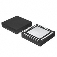
QFN32 PACKAGE
(TOP VIEW)
NC
CLKA
CLKA
VBB
•
•
2× One Differential Clock Input Pair LVPECL to
5 Differential LVPECL Clock Outputs
Fully Compatible With LVPECL/LVECL
Supports a Wide Supply Voltage Range From
2.375 V to 3.8 V
Open Input Default State
Low-Output Skew (Typ 15 ps) for
Clock-Distribution Applications
VBB Reference Voltage Output for
Single-Ended Clocking
Available in the QFN32 Package
Frequency Range From DC to 3.5 GHz
Pin-to-Pin Compatible With the MC100 Series
EP111, LVEP210, ES6111, LVEP111
VCC
•
2
Designed for Driving 50-Ω Transmission Lines
High Performance Clock Distribution
DESCRIPTION
The CDCLVP215 clock driver distributes two times one differential clock pair of LVPECL, (CLKA, CLKB) to 5
pairs of differential LVPECL clock (QA0..QA4, QB0..QB4) outputs with minimum skew for clock distribution. The
CDCLVP215 specifies low output-to-output skew. The CDCLVP215 is specifically designed for driving 50-Ω
transmission lines. When an output pair is not used, leaving it open is recommended to reduce power
consumption. If only one of the output pairs is used, the other output pair must be identically terminated to 50 Ω.
The VBB reference voltage output is used if single-ended input operation is required. In this case, the VBB pin
should be connected to CLKA or CLKB and bypassed to GND via a 10-nF capacitor.
However, for high-speed performance up to 3.5 GHz, the differential mode is strongly recommended.
The CDCLVP215 is characterized for operation from –40°C to 85°C.
1
2
Please be aware that an important notice concerning availability, standard warranty, and use in critical applications of Texas
Instruments semiconductor products and disclaimers thereto appears at the end of this data sheet.
PowerPAD is a trademark of Texas Instruments.
PRODUCTION DATA information is current as of publication date.
Products conform to specifications per the terms of the Texas
Instruments standard warranty. Production processing does not
necessarily include testing of all parameters.
Copyright © 2008–2009, Texas Instruments Incorporated
�CDCLVP215
SCAS853B – APRIL 2008 – REVISED NOVEMBER 2009
www.ti.com
This integrated circuit can be damaged by ESD. Texas Instruments recommends that all integrated circuits be handled with
appropriate precautions. Failure to observe proper handling and installation procedures can cause damage.
ESD damage can range from subtle performance degradation to complete device failure. Precision integrated circuits may be more
susceptible to damage because very small parametric changes could cause the device not to meet its published specifications.
31
30
29
28
27
26
24
23
CLKA
+
CLKA
CLKB
+
3
22
4
21
6
20
7
19
18
CLKB
17
15
14
13
12
11
5
VBB
QA0
QA0
QA1
QA1
QA2
QA2
QA3
QA3
QA4
QA4
QB0
QB0
QB1
QB1
QB2
QB2
QB3
QB3
QB4
10
QB4
PIN FUNCTIONS
PIN
NAME
NC
DESCRIPTION
NO.
2
Not connected
CLKA, CLKA
3, 4
Differential LVECL/LVPECL input pair
CLKB, CLKB
6, 7
Differential LVECL/LVPECL input pair
Q [A0:A4]
22, 24, 27, 29, 31
LVECL/LVPECL clock outputs, these outputs provide low-skew copies of CLKA.
Q [A0:A4]
21,23, 26, 28, 30
LVECL/LVPECL complementary clock outputs, these outputs provide low-skew copies of
CLKA.
Q [B0:B4]
11, 13, 15, 18, 20
LVECL/LVPECL clock outputs, these outputs provide low-skew copies of CLKB.
Q [B0:B4]
10, 12, 14, 17, 19
LVECL/LVPECL complementary clock outputs, these outputs provide low-skew copies of
CLKB.
VBB
5
VCC
1, 9, 16, 25, 32
VEE
8
Device ground or negative supply voltage in ECL mode
PowerPAD™
0
The PowerPAD of the QFN32 package is thermally connected to the die to improve the heat
transfer out of the package. This pad is connected to VEE.
•
•
•
CLKn pull down resistor 75 kΩ
CLKn pull up resistor 37.5 kΩ
CLKn pull down resistor 50 kΩ
2
Submit Documentation Feedback
Reference voltage output for single-ended input operation
Supply voltage
Copyright © 2008–2009, Texas Instruments Incorporated
Product Folder Link(s): CDCLVP215
�CDCLVP215
www.ti.com
SCAS853B – APRIL 2008 – REVISED NOVEMBER 2009
ABSOLUTE MAXIMUM RATINGS
over operating free-air temperature range (unless otherwise noted)
VALUE
UNIT
–0.3 to 4.6
V
Input voltage
–0.3 to VCC + 0.5
V
Output voltage
–0.3 to VCC + 0.5
V
±20
mA
-4.6 to 0.3
V
–1 to 1
mA
–50
mA
–65 to 150
°C
VCC
Supply voltage (relative to VEE)
VI
VO
IIN
Input current
VEE
Negative supply voltage (relative to VCC)
IBB
Sink/source current
IO
DC output current
Tstg
Storage temperature range
RECOMMENDED OPERATING CONDITIONS
VCC
Supply voltage (relative to VEE)
TA
Operating free-air temperature
MIN
NOM
MAX
2.375
2.5/3.3
3.8
V
85
°C
–40
UNIT
PACKAGE THERMAL IMPEDANCE
TEST CONDITION
θJA
θJC
(1)
Thermal resistance junction to ambient (1)
MIN
MAX
UNIT
0 LFM
49
°C/W
150 LFM
37
°C/W
250 LFM
36
°C/W
500 LFM
32
°C/W
19
°C/W
MAX
UNIT
Thermal resistance junction to case
According to JESD 51-7 standard.
LVECL DC ELECTRICAL CHARACTERISTICS
Vsupply: VCC = 0 V, VEE = –2.375 V to –3.8 V
over operating free-air temperature range (unless otherwise noted)
PARAMETER
TEST CONDITIONS
IEE
Supply internal current
Absolute value of current
ICC
Output and internal supply
current
All outputs terminated 50 Ω to VCC – 2 V
IIN
VBB
Input current
TYP
40
90
–40°C
354
25°C
380
85°C
405
mA
mA
Includes pullup/pulldown resistors
VIH = VCC, VIL = VCC - 2 V
–40°C,
25°C,
85°C
–150
For VEE = –3 to –3.8 V, IBB = –0.2 mA
–40°C,
25°C,
85°C
–1.45
VEE = –2.375 to –2.75 V, IBB = –0.2 mA
–40°C,
25°C,
85°C
–1.4
(1)
-40°C,
25°C,
85°C
0.5
1.3
V
-40°C,
25°C,
85°C
VEE + 1
–0.3
V
Internally generated bias
voltage
VID
Input amplitude (CLKn, CLKn)
Difference of input | VIH – VIL | , See
VCM
Common-mode voltage
(CLKn, CLKn)
DC offset relative to VEE
(1)
MIN
–40°C,
25°C,
85°C
150
–1.3
μA
–1.15
V
–1.25
–1.1
VID minimum and maximum is required to maintain ac specifications, actual device function tolerates a minimum VID of 100 mV.
Submit Documentation Feedback
Copyright © 2008–2009, Texas Instruments Incorporated
Product Folder Link(s): CDCLVP215
3
�CDCLVP215
SCAS853B – APRIL 2008 – REVISED NOVEMBER 2009
www.ti.com
LVECL DC ELECTRICAL CHARACTERISTICS (continued)
Vsupply: VCC = 0 V, VEE = –2.375 V to –3.8 V
over operating free-air temperature range (unless otherwise noted)
PARAMETER
TEST CONDITIONS
MIN
–40°C
VOH
VOL
VOD
High-level output voltage
IOH = –21 mA
Low-level output voltage
IOL = –5 mA
Differential output voltage swing
Terminated with 50 Ω to VCC – 2 V,
See Figure 3
TYP
MAX
–1.26
–0.85
25°C
–1.2
–0.85
85°C
–1.15
–0.85
–40°C
–1.85
–1.5
25°C
–1.85
–1.45
85°C
–1.85
–1.4
–40°C
25°C,
85°C
600
UNIT
V
V
mV
LVPECL DC ELECTRICAL CHARACTERISTICS
Vsupply: VCC = 2.375 V to 3.8 V, VEE= 0 V
over operating free-air temperature range (unless otherwise noted)
PARAMETER
TEST CONDITIONS
IEE
Supply internal current
Absolute value of current
ICC
Output and internal
supply current
All outputs terminated 50 Ω to VCC – 2 V
IIN
VBB
Input current
380
85°C
405
mA
VCC – 1.45
VCC = 2.375 to 2.75 V, IBB = –0.2 mA
–40°C,
25°C,
85°C
VCC – 1.4
–40°C,
25°C,
85°C
0.5
1.3
V
–40°C,
25°C,
85°C
1
VCC – 0.3
V
–40°C
VCC – 1.26
VCC – 0.85
25°C
VCC – 1.2
VCC – 0.85
85°C
VCC – 1.15
VCC – 0.85
–40°C
VCC – 1.85
VCC – 1.5
25°C
VCC - 1.85
VCC – 1.45
85°C
VCC – 1.85
VCC – 1.4
Common-mode
voltage (CLKn, CLKn)
DC offset relative to VEE
VOH
High-level output
voltage
4
354
25°C
–40°C,
25°C,
85°C
VCM
(1)
-40°C
mA
VCC = 3 to 3.8 V, IBB= –0.2 mA
Difference of input | VIH – VIL| , see
Differential output
voltage swing
90
UNIT
–150
Input amplitude (CLKn,
CLKn)
VOD
40
MAX
Includes pullup/pulldown resistors
VIH = VCC, VIL = VCC - 2 V
Internally generated
bias voltage
Low-level output
voltage
TYP
–40°C,
25°C,
85°C
VID
VOL
MIN
–40°C,
25°C,
85C
IOH = –21 mA
IOL = –5 mA
Terminated with 50 Ω to VCC – 2 V
(1)
–40°C,
25°C,
85°C
150
VCC – 1.3
μA
VCC – 1.15
V
VCC – 1.25
VCC – 1.1
600
V
V
mV
VID minimum and maximum is required to maintain ac specifications, actual device function tolerates a minimum VID of 100 mV.
Submit Documentation Feedback
Copyright © 2008–2009, Texas Instruments Incorporated
Product Folder Link(s): CDCLVP215
�CDCLVP215
www.ti.com
SCAS853B – APRIL 2008 – REVISED NOVEMBER 2009
AC ELECTRICAL CHARACTERISTICS
Vsupply: VCC = 2.375 V to 3.8 V, VEE = 0 V or LVECL/LVPECL input VCC = 0 V, VEE = -2.375 V to -3.8 V
over operating free-air temperature range (unless otherwise noted)
PARAMETER
TEST CONDITIONS
MAX
UNIT
300
ps
30
ps
70
ps
Additive phase jitter, rms
Integration bandwidth of
20 kHz to 20 MHz,
fout = 125 MHz at 25°C
< 0.8
ps
f(max)
Maximum frequency
Functional up to 3.5 GHz, timing
specifications apply at 1 GHz,
see Figure 3
3500
MHz
tr/tf
Output rise and fall time (20%, 80%)
200
ps
tpd
Differential propagation delay CLKn, CLKn
to all QA0, QA0… QB4, QB4
Input condition: VCM = 1 V,
VID = 0.5 V
tsk(o)
Output-to-output skew
See Note A of Figure 1
tsk(pp)
Part-to-part skew
See Note B of Figure 1
taj
MIN
TYP
135
15
90
CLKn
CLKn
tPLHn0
tPLHn0
tPLHn1
tPLHn1
Qn0
Qn0
Qn1
Qn1
tPLHn2
Qn2
tPLHn2
Qn2
o
o
o
o
o
tPLHn4
tPLHn4
Qn4
Qn4
A.
Output skew is calculated as the greater of: The difference between the fastest and the slowest tPLHn (n = n0,
n1,...n4) or the difference between the fastest and the slowest tPHLn (n = n0, n1,...n4).
B.
Part-to-part skew, is calculated as the greater of: The difference between the fastest and the slowest tPLHn (n = n0,
n1,...n4) across multiple devices or the difference between the fastest and the slowest tPHLn (n = n0, n1,...n4) across
multiple devices.
C.
Output skew is measured per the output group.
Figure 1. Waveform for Calculating Both Output and Part-to-Part Skew
Submit Documentation Feedback
Copyright © 2008–2009, Texas Instruments Incorporated
Product Folder Link(s): CDCLVP215
5
�CDCLVP215
SCAS853B – APRIL 2008 – REVISED NOVEMBER 2009
www.ti.com
VCC
ZO = 50 W
Yn
CDCLVP215
Driver
LVPECL
Receiver
ZO = 50 W
Yn
50 W
50 W
VEE
VT = VCC - 2 V
Figure 2. Typical Termination for Output Driver (See the Application Note Interfacing Between LVPECL,
LVDS, and CML, Literature Number SCAA056)
VODmin - Differential Output Voltage Swing - mV
DIFFERENTIAL OUTPUT VOLTAGE SWING
vs
FREQUENCY
900
800
VCC = 2.375 V
TA = -40°C to 85°C
700
600
500
400
300
200
100
0
1
1.5
2
2.5
3
3.5
f - Frequency - GHz
Figure 3. LVPECL Input Using CLKB Pair, VCM = 1 V, VID = 0.5 V
6
Submit Documentation Feedback
Copyright © 2008–2009, Texas Instruments Incorporated
Product Folder Link(s): CDCLVP215
�CDCLVP215
www.ti.com
SCAS853B – APRIL 2008 – REVISED NOVEMBER 2009
REVISION HISTORY
Changes from Original (April 2008) to Revision A
Page
•
Changed Status from: Product Preview To: Production ....................................................................................................... 1
•
Changed Features bullet From: Fully Compatible With LVPECL/LVPECL To: Fully Compatible With LVPECL/LVECL .... 1
•
Changed Features Bullet From: Single Supply Voltage Required ±3.3 V or ±2.5 V Supply To: Supports a Wide
Supply Voltage Range From 2.375 V to 3.8 V ..................................................................................................................... 1
•
Deleted PTN1111 from The Pin-to-Pin Features bullet ........................................................................................................ 1
•
Changed EP210 in The Pin-to-Pin Features bullet From: EP210 to LVEP210. ................................................................... 1
•
Added Application bullet: High Performance Clock Distribution ........................................................................................... 1
•
Changed paragraph - From: The bottom of the QFN32 To: The PowerPAD™ of the QFN32... ......................................... 2
•
Changed list item From: CLKn pull up resistor 31.4 kΩ To: CLKn pull up resistor 37.5 kΩ ................................................ 2
•
Changed Abs Max table - Negative supply voltage value From -0.3 to 4.6 To: -4.6 to 0.3 ................................................. 3
•
Changed PACKAGE THERMAL IMPEDANCE max values. ................................................................................................ 3
•
Changed LVECL DC ELECTRICAL CHARACTERISTICS values. ...................................................................................... 3
•
Added to the input current Test Conditions: VIH = VCC, VIL = VCC - 2V ................................................................................. 3
•
Changed From: Cross point of input 9 average (VIH, VIL) To: DC offset relative to VEE ....................................................... 3
•
Changed LVPECL DC ELECTRICAL CHARACTERISTICS values. ................................................................................... 4
•
Added to the input current Test Conditions: VIH = VCC, VIL = VCC - 2V ................................................................................. 4
•
Changed From: Cross point of input 9 average (VIH, VIL) To: DC offset relative to VEE ....................................................... 4
•
Changed AC ELECTRICAL CHARACTERISTICS values. ................................................................................................... 5
•
Changed From: Cycle to Cycle RMS jitter To: Additive phase jitter. .................................................................................... 5
•
Changed Output rise and fall time (20%, 80%) MIN Value From: 100 To: 90 ..................................................................... 5
Changes from Revision A (October 2008) to Revision B
Page
•
Added PowerPAD information to the Pinout Package .......................................................................................................... 1
•
Added PowerPAD information to the Pin Functions table .................................................................................................... 2
•
Deleted The PowerPAD™ of the QFN32 ............................................................................................................................. 2
Submit Documentation Feedback
Copyright © 2008–2009, Texas Instruments Incorporated
Product Folder Link(s): CDCLVP215
7
�PACKAGE OPTION ADDENDUM
www.ti.com
10-Dec-2020
PACKAGING INFORMATION
Orderable Device
Status
(1)
Package Type Package Pins Package
Drawing
Qty
Eco Plan
(2)
Lead finish/
Ball material
MSL Peak Temp
Op Temp (°C)
Device Marking
(3)
(4/5)
(6)
CDCLVP215RHBR
ACTIVE
VQFN
RHB
32
3000
RoHS & Green
NIPDAU
Level-2-260C-1 YEAR
-40 to 85
LVP215
CDCLVP215RHBT
ACTIVE
VQFN
RHB
32
250
RoHS & Green
NIPDAU
Level-2-260C-1 YEAR
-40 to 85
LVP215
(1)
The marketing status values are defined as follows:
ACTIVE: Product device recommended for new designs.
LIFEBUY: TI has announced that the device will be discontinued, and a lifetime-buy period is in effect.
NRND: Not recommended for new designs. Device is in production to support existing customers, but TI does not recommend using this part in a new design.
PREVIEW: Device has been announced but is not in production. Samples may or may not be available.
OBSOLETE: TI has discontinued the production of the device.
(2)
RoHS: TI defines "RoHS" to mean semiconductor products that are compliant with the current EU RoHS requirements for all 10 RoHS substances, including the requirement that RoHS substance
do not exceed 0.1% by weight in homogeneous materials. Where designed to be soldered at high temperatures, "RoHS" products are suitable for use in specified lead-free processes. TI may
reference these types of products as "Pb-Free".
RoHS Exempt: TI defines "RoHS Exempt" to mean products that contain lead but are compliant with EU RoHS pursuant to a specific EU RoHS exemption.
Green: TI defines "Green" to mean the content of Chlorine (Cl) and Bromine (Br) based flame retardants meet JS709B low halogen requirements of