User's Guide
SLLU136A – September 2011 – Revised November 2012
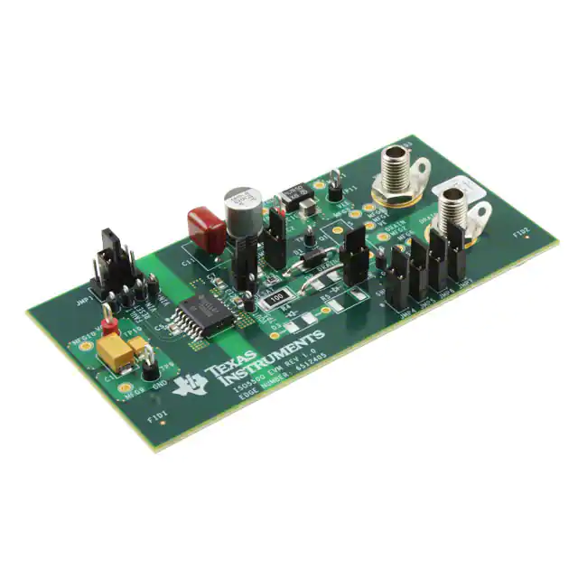
ISO5500EVM
This document describes the ISO5500 Evaluation Module (EVM) and allows designers to analyze and
evaluate the Texas Instruments ISO5500 Isolated Gate Driver.
The ISO5500EVM can be used to evaluate device parameters while acting as a guide for board layout.
The board allows the user to evaluate device performance using a simulated (10-nF) IGBT load installed
on the board, or to install an IGBT or MOSFET (TO-247 package) onto the board and drive it with the
ISO5500.
1
2
Contents
Introduction ..................................................................................................................
1.1
Overview ............................................................................................................
1.2
ISO5500EVM Kit Contents .......................................................................................
Printed-Circuit Board .......................................................................................................
2.1
ISO5500 Operation ................................................................................................
2.2
Schematic and Bill of Materials ..................................................................................
1
1
2
2
2
5
List of Figures
1
2
3
4
........................................................................
High-Side Interconnection Diagram ......................................................................................
Low-Side Interconnection Diagram .......................................................................................
Component Changes to Change Turnon/Turnoff .......................................................................
ISO5500 Pinout and Functional Block Diagram
2
4
4
5
List of Tables
1
Test Points ................................................................................................................... 5
2
Bill of Materials .............................................................................................................. 6
1
Introduction
1.1
Overview
This ISO5500EVM was designed to allow the user to evaluate the performance and features of the
ISO5500. This includes the IGBT desaturation protection (DESAT) and the UVLO circuit that ensures a
sufficient gate voltage is available to drive the IGBT or MOSFET. The printed-circuit board (PCB) also
includes provisions to adjust the turnon/turnoff characteristics by changing the loading between the
ISO5500 output and the IGBT (or MOSFET) gate.
The EVM kit includes the ISO5500 data sheet. Figure 1 shows the device pinout and the functional block
diagram.
QuietZone is a trademark of 3M.
SLLU136A – September 2011 – Revised November 2012
Submit Documentation Feedback
Copyright © 2011–2012, Texas Instruments Incorporated
ISO5500EVM
1
�Printed-Circuit Board
www.ti.com
DEVICE PINOUT
1
2
3
4
5
6
7
8
VIN+
VE
VIN-
VEE
VCC1
16
15
14
DESAT
VCC2
13
VC
12
VOUT
11
NC
VEE
10
GND1
VEE
9
GND1
RESET
FAULT
Figure 1. ISO5500 Pinout and Functional Block Diagram
1.2
ISO5500EVM Kit Contents
•
•
•
2
ISO5500EVM printed-circuit board with ISO5500DW installed (P/N 6512405)
ISO5500EVM User’s Guide (This document)
ISO5500 data sheet
Printed-Circuit Board
The ISO5500 is an isolated gate driver with several important features. The printed-circuit board (PCB)
has been designed to support this device and to allow the user to evaluate its basic operation and
features. The left side of the PCB contains the interface to the input, control, and status functions of the
integrated circuit (IC). The right side of the PCB has been designed to interface to an IGBT (or MOSFET).
No electrical connections exist between the right and left sides of the PCB.
Refer to the ISO5500EVM schematic and bill of materials to become familiar with the PCB components
and layout. The PCB files (Gerber/ODB) are available from Texas Instruments on request.
2.1
ISO5500 Operation
2.1.1
Left-Side Operation: DC Power, Control, and Status
2.1.1.1
DC Power
The left side of the ISO5500 (and therefore the PCB) can be operated using either a +3.3-V (±10%) or +5V (±10%) dc power supply. The small amount of dc current required (
很抱歉,暂时无法提供与“ISO5500EVM”相匹配的价格&库存,您可以联系我们找货
免费人工找货