Order
Now
Product
Folder
Support &
Community
Tools &
Software
Technical
Documents
ISO7240CF, ISO7240C, ISO7240M
ISO7241C, ISO7241M, ISO7242C, ISO7242M
SLLS868T – SEPTEMBER 2007 – REVISED APRIL 2017
ISO724x High-Speed, Quad-Channel Digital Isolators
1 Features
3 Description
•
The ISO7240x, ISO7241x, and ISO7242x devices are
quad-channel digital isolators with multiple channel
configurations and output-enable functions. These
devices have logic-input and logic-output buffers
separated by Texas Instrument’s silicon-dioxide
(SiO2) isolation barrier. Used in conjunction with
isolated power supplies, these devices help block
high voltage, isolate grounds, and prevent noise
currents from entering the local ground and interfering
with or damaging sensitive circuitry.
1
•
•
•
•
•
•
•
25 and 150-Mbps Signaling Rate Options
– Low Channel-to-Channel Output Skew;
1 ns Maximum
– Low Pulse-Width Distortion (PWD);
2 ns Maximum
– Low Jitter Content; 1 ns Typ at 150 Mbps
Selectable Default Output (ISO7240CF)
> 25-Year Life at Rated Working Voltage
(see High-Voltage Lifetime of the ISO72x Family
of Digital Isolators and Isolation Capacitor Lifetime
Projection)
4-kV ESD Protection
Operates With 3.3-V or 5-V Supplies
High Electromagnetic Immunity
(see ISO72x Digital Isolator Magnetic-Field
Immunity)
–40°C to +125°C Operating Temperature Range
Safety-Related Certifications:
– VDE 4000 VPK Basic Insulation per DIN V VDE
V 0884-10 (VDE V 0884-10):2006-12
– 2.5 kVRMS Insulation for 1 minute per UL 1577
– CSA Component Acceptance Notice #5A and
IEC 60950-1 End Equipment Standard
The ISO7240x family of devices has all four channels
in the same direction. The ISO7241x family of
devices has three channels in the same direction and
one channel in the opposition direction. The
ISO7242x family of devices has two channels in each
direction.
Device Information(1)
PART NUMBER
BODY SIZE (NOM)
SOIC (16)
10.30 mm × 7.50 mm
ISO7240C
ISO7240M
ISO7241C
ISO7241M
ISO7242C
ISO7242M
(1) For all available packages, see the orderable addendum at
the end of the data sheet.
2 Applications
•
•
•
•
PACKAGE
ISO7240CF
Industrial Fieldbus
Computer Peripheral Interface
Servo Control Interface
Data Acquisition
Simplified Schematic
VCCI
INx
Isolation
Capacitor
VCCO
OUTx
Disable
(ISO7240CF only)
GNDI
ENx
or
CTRL (ISO7240CF only)
GNDO
Copyright © 2016, Texas Instruments Incorporated
VCCI and GNDI are supply and ground connections respectively for the input channels.
VCCO and GNDO are supply and ground connections respectively for the output channels.
1
An IMPORTANT NOTICE at the end of this data sheet addresses availability, warranty, changes, use in safety-critical applications,
intellectual property matters and other important disclaimers. PRODUCTION DATA.
�ISO7240CF, ISO7240C, ISO7240M
ISO7241C, ISO7241M, ISO7242C, ISO7242M
SLLS868T – SEPTEMBER 2007 – REVISED APRIL 2017
www.ti.com
Table of Contents
1
2
3
4
5
6
7
Features ..................................................................
Applications ...........................................................
Description .............................................................
Revision History.....................................................
Description (Continued) ........................................
Pin Configurations and Functions .......................
Specifications.........................................................
7.18 Switching Characteristics: VCC1 at 5-V, VCC2 at 3.3V Operation ............................................................. 16
7.19 Switching Characteristics: VCC1 at 3.3-V and VCC2
at 5-V Operation....................................................... 17
7.20 Switching Characteristics: VCC1 and VCC2 at 3.3-V
Operation ................................................................ 17
7.21 Insulation Characteristics Curves ......................... 18
7.22 Typical Characteristics .......................................... 19
1
1
1
2
7
8
9
7.1
7.2
7.3
7.4
7.5
7.6
7.7
7.8
7.9
Absolute Maximum Ratings ...................................... 9
ESD Ratings.............................................................. 9
Recommended Operating Conditions....................... 9
Thermal Information ................................................ 10
Power Ratings......................................................... 10
Insulation Specifications.......................................... 11
Safety-Related Certifications................................... 11
Safety Limiting Values ............................................ 12
Electrical Characteristics: VCC1 and VCC2 at 5-V
Operation ................................................................. 12
7.10 Supply Current Characteristics: VCC1 and VCC2 at 5V Operation.............................................................. 12
7.11 Electrical Characteristics: VCC1 at 5-V, VCC2 at 3.3-V
Operation ................................................................. 13
7.12 Supply Current Characteristics: VCC1 at 5-V, VCC2 at
3.3-V Operation........................................................ 13
7.13 Electrical Characteristics: VCC1 at 3.3-V, VCC2 at 5-V
Operation ................................................................. 14
7.14 Supply Current Characteristics: VCC1 at 3.3-V, VCC2
at 5-V Operation....................................................... 14
7.15 Electrical Characteristics: VCC1 and VCC2 at 3.3 V
Operation ................................................................. 15
7.16 Supply Current Characteristics: VCC1 and VCC2 at
3.3 V Operation........................................................ 15
7.17 Switching Characteristics: VCC1 and VCC2 at 5-V
Operation ................................................................. 16
8
9
Parameter Measurement Information ................ 21
Detailed Description ............................................ 24
9.1
9.2
9.3
9.4
Overview .................................................................
Functional Block Diagram .......................................
Feature Description.................................................
Device Functional Modes........................................
24
24
25
25
10 Application and Implementation........................ 27
10.1 Application Information.......................................... 27
10.2 Typical Application ................................................ 27
11 Power Supply Recommendations ..................... 32
12 Layout................................................................... 32
12.1 Layout Guidelines ................................................. 32
12.2 Layout Example .................................................... 32
13 Device and Documentation Support ................. 33
13.1
13.2
13.3
13.4
13.5
13.6
13.7
Documentation Support ........................................
Related Links ........................................................
Receiving Notification of Documentation Updates
Community Resources..........................................
Trademarks ...........................................................
Electrostatic Discharge Caution ............................
Glossary ................................................................
33
33
33
33
33
34
34
14 Mechanical, Packaging, and Orderable
Information ........................................................... 34
4 Revision History
NOTE: Page numbers for previous revisions may differ from page numbers in the current version.
Changes from Revision S (April 2016) to Revision T
Page
•
Added isolation resistance for 100°C ≤ TA ≤ 125°C in the Insulation Specifications table................................................... 11
•
Deleted the maximum transient overvoltage from VDE in the Safety-Related Certifications table...................................... 11
•
Added the Receiving Notification of Documentation Updates and the Community Resources section............................... 33
Changes from Revision R (September 2015) to Revision S
Page
•
Changed the HBM value from ±4 V to ±4000 V and the CDM value from ±1 V to ±1000 V in the ESD Ratings table......... 9
•
Moved the device power dissipation parameter from the Thermal Information table to the Power Dissipation
Characteristics table ............................................................................................................................................................ 10
Changes from Revision Q (January 2015) to Revision R
Page
•
Changed Features From: "Basic Isolation per DIN EN 60747-5-5 (VDE 0884-5) & DIN EN 61010-1" To:"Basic
Insulation per DIN V VDE V 0884-10 (VDE V 0884-10):2006-12" ......................................................................................... 1
•
Changed VCC1 To VCCI, VCC2 To VCCO, GND1 To GNDI, and GND2 To GNDO, and added Notes 1 and 2 to the
2
Submit Documentation Feedback
Copyright © 2007–2017, Texas Instruments Incorporated
Product Folder Links: ISO7240CF ISO7240C ISO7240M ISO7241C ISO7241M ISO7242C ISO7242M
�ISO7240CF, ISO7240C, ISO7240M
ISO7241C, ISO7241M, ISO7242C, ISO7242M
www.ti.com
SLLS868T – SEPTEMBER 2007 – REVISED APRIL 2017
Simplified Schematic .............................................................................................................................................................. 1
•
Changed the CTI Test Conditions From: IEC 60112/VDE 0303 Part 1 To: DIN EN 60112 (VDE 0303-11); IEC 60112
in the Package Characteristics table ................................................................................................................................... 11
•
Changed section title From: DIN EN 60747-5-5 Insulation Characteristics To: DIN V VDE V 0884-10 (VDE V 088410):2006-1 Insulation Characteristics( .................................................................................................................................. 11
•
Deleted CI - Input capacitance to ground from the Package Characteristics table ............................................................. 11
•
Changed RS Test Conditions From: VIO = 500 V at TS To: VIO = 500 V at TS = 150°C in the DIN V VDE V 0884-10
(VDE V 0884-10):2006-1 Insulation Characteristics table.................................................................................................... 11
•
Changed "DIN EN 60747-5-5 & DIN EN 61010-1" To: DIN V VDE V 0884-10 (VDE V 0884-10):2006-12 and DIN EN
61010-1 (VDE 0411-1): 2011-07 in the Regulatory Information table.................................................................................. 11
•
Changed title From: IEC Safety Limiting Values To: Safety Limiting Values ....................................................................... 12
•
Changed VOH MIN values From: VCC - 0.8 To: VCCO - 0.8 and VCC - 0.1 To: VCCO - 0.1 in the Electrical
Characteristics: VCC1 and VCC2 at 5-V Operation ................................................................................................................. 12
•
Changed VOH Test Condition ISO7240 To: 3.3-V side and the MIN value From: VCC - 0.4 To VCCO -0.4 in the
Electrical Characteristics: VCC1 at 5-V, VCC2 at 3.3-V Operation .......................................................................................... 13
•
Changed VOH Test Condition ISO724x (5-V side) To: 5-V side and the MIN value From: VCC - 0.8 To: VCCO - 0.8 in
the Electrical Characteristics: VCC1 at 5-V, VCC2 at 3.3-V Operation .................................................................................... 13
•
Changed VOH, Test Condition IOH = -20 µA MIN value From: VCC - 0.1 To VCCO - 0.1 in the lectrical Characteristics:
VCC1 at 5-V, VCC2 at 3.3-V Operation ............................................................................................................................... 13
•
Changed VOH Test Condition ISO7240 To: 3.3-V side and the MIN value From: VCC - 0.4 To VCCO -0.4 in the
Electrical Characteristics: VCC1 at 3.3-V, VCC2 at 5-V Operation .......................................................................................... 14
•
Changed VOH Test Condition ISO724x (5-V side) To: 5-V side and the MIN value From: VCC - 0.8 To: VCCO - 0.8 in
the Electrical Characteristics: VCC1 at 3.3-V, VCC2 at 5-V Operation .................................................................................... 14
•
Changed VOH, Test Condition IOH = -20 µA MIN value From: VCC - 0.1 To VCCO - 0.1 in the Electrical Characteristics:
VCC1 at 3.3-V, VCC2 at 5-V Operation .................................................................................................................................... 14
•
Changed VOH MIN values From: VCC - 0.4 To: VCCO - 0.4 and VCC - 0.1 To: VCCO - 0.1 in the Electrical
Characteristics: VCC1 and VCC2 at 3.3 V Operation .............................................................................................................. 15
•
Changed Figure 2 title From: Thermal Derating Curve per DIN EN 60747-5-5 To: Thermal Derating Curve per VDE ...... 18
•
Changed VCC1 To: VCCI and VCC2 To: VCCO in Common-Mode Transient Immunity Test Circuit and Voltage Waveform ... 23
Changes from Revision P (August 2014) to Revision Q
Page
•
Changed the VI MAX value in the Absolute Maximum Ratings table From: 6 V To: VCC + 0.5 V .......................................... 9
•
Added Note 3 to the Absolute Maximum Ratings table.......................................................................................................... 9
•
Moved TSTG - Storage From the ESD Ratings table to the Absolute Maximum Ratings table .............................................. 9
•
Changed the Handling Rating table to the ESD Ratings table. ............................................................................................. 9
•
Added one row to the ISO7240CF Functions Table table. Values: X, PD, X, X, X, Undetermined .................................... 25
•
Added one row to the Device Function Table ISO724x table. Values: X, PD, X, X, Undetermined ................................... 25
•
Changed the Device I/O Schematics labels From: "ISO7240CF Input" To: "ISO7240CF Input, Disable" and From:
"Enable" To: "Enable, Control" ............................................................................................................................................ 26
Changes from Revision O (November 2012) to Revision P
Page
•
Added Pin Configuration and Functions section, Handling Rating table, Feature Description section, Device
Functional Modes, Application and Implementation section, Power Supply Recommendations section, Layout
section, Device and Documentation Support section, and Mechanical, Packaging, and Orderable Information
section ................................................................................................................................................................................... 1
•
Changed ISO7241C minimum supply from 2.8 V to 3.15 V................................................................................................... 9
Copyright © 2007–2017, Texas Instruments Incorporated
Submit Documentation Feedback
Product Folder Links: ISO7240CF ISO7240C ISO7240M ISO7241C ISO7241M ISO7242C ISO7242M
3
�ISO7240CF, ISO7240C, ISO7240M
ISO7241C, ISO7241M, ISO7242C, ISO7242M
SLLS868T – SEPTEMBER 2007 – REVISED APRIL 2017
www.ti.com
Changes from Revision N (January 2012) to Revision O
•
Page
Added the Safety Limiting Values section ............................................................................................................................ 12
Changes from Revision M (January 2011) to Revision N
Page
•
Changed Feature From: Operates 3.3-V or 5-V Supplies To: Operates With 2.8-V (ISO7241C), 3.3-V or 5-V Supplies ..... 1
•
Added device options to VCC in the RECOMMENDED OPERATING CONDITIONS table ................................................... 9
•
Changed Table Note (1) ......................................................................................................................................................... 9
•
Changed the CTI MIN value From: ≥175 V To:≥400 V ........................................................................................................ 11
•
Changed the Regulatory Information table........................................................................................................................... 11
•
Changed Table Note (1) ....................................................................................................................................................... 12
•
Changed ICC1 and ICC2 test conditions in the VCC1 and VCC2 at 5-V Electrical Characteristics: VCC1 and VCC2 at 5-V
Operation table ..................................................................................................................................................................... 12
•
Changed Table Note (1) ....................................................................................................................................................... 13
•
Changed ICC1 and ICC2 test conditions in the VCC1 at 5-V, VCC2 at 3.3-V Electrical Characteristics: VCC1 at 5-V, VCC2 at
3.3-V Operation table ........................................................................................................................................................... 13
•
Changed Table Note (1) ....................................................................................................................................................... 14
•
Changed ICC1 and ICC2 test conditions in the VCC1 at 3.3-V, VCC2 at 5-V Electrical Characteristics: VCC1 at 3.3-V, VCC2
at 5-V Operation table .......................................................................................................................................................... 14
•
Changed Table Note (1) ....................................................................................................................................................... 15
•
Added ELECTRICAL and Switching CHARACTERISTICS tables forVCC1 and VCC2 at 2.8V (ISO722xC-only)................... 15
•
Changed ICC1 and ICC2 test conditions in the VCC1 and VCC2 at 3.3 V table .......................................................................... 15
•
Changed VCC Undervoltage Threshold vs Free-Air Temperature From VCC1 Failsafe Threshold To: VCC Undervoltage
Threshold.............................................................................................................................................................................. 19
Changes from Revision L (January 2010) to Revision M
Page
•
Changed the CSA File Number From: 1698195 To: 220991 ............................................................................................... 11
•
Changed Switching Characteristic Test Circuit and Voltage Waveforms, Failsafe Delay Time Test Circuit and
Voltage Waveforms, and Wake Time From Input Disable Test Circuit and Voltage Waveforms ........................................ 21
Changes from Revision K (Decemberl 2009) to Revision L
Page
•
Added CTI - Tracking resistance (comparative tracking index to the Package Characteristics table.................................. 11
•
Added the IEC 60664-1 RATINGS TABLE .......................................................................................................................... 11
•
Added the IEC 60747-5-2 INSULATION CHARACTERISTIC table..................................................................................... 11
Changes from Revision J (April 2009) to Revision K
Page
•
Changed the Input circuit in the DEVICE I/O SCHEMATICS illustration ............................................................................... 1
•
Added Note 1 to LI01), and changed the MIN value From: 8.34 To 8 mm in the Package Characteristics table .............. 11
•
Added Note 1 to LI02), and changed the MIN value From: 8.1 To 8 mm in the Package Characteristics table ................ 11
Changes from Revision I (December 2008) to Revision J
Page
•
Changed ICC1 for Quiescent and 1Mbps From: 10mA To: 11mA ......................................................................................... 12
•
Changed ICC1 for Quiescent and 1Mbps From: 10mA To: 11mA ......................................................................................... 13
4
Submit Documentation Feedback
Copyright © 2007–2017, Texas Instruments Incorporated
Product Folder Links: ISO7240CF ISO7240C ISO7240M ISO7241C ISO7241M ISO7242C ISO7242M
�ISO7240CF, ISO7240C, ISO7240M
ISO7241C, ISO7241M, ISO7242C, ISO7242M
www.ti.com
SLLS868T – SEPTEMBER 2007 – REVISED APRIL 2017
Changes from Revision G (July 2008) to Revision H
Page
•
Added Device number ISO7240CF. ....................................................................................................................................... 1
•
Added Features Bullet: Selectable Failsafe Output (ISO7240CF) ......................................................................................... 1
•
Changed description paragraph 4 text. .................................................................................................................................. 7
•
Changed VI in the Absolute Maximum Ratings table From: Voltage at IN, OUT, EN To: Voltage at IN, OUT, EN,
DISABLE, CTRL ..................................................................................................................................................................... 9
•
Added twake, Wake time from input disable ........................................................................................................................... 16
•
Added twake, Wake time from input disable ........................................................................................................................... 16
•
Added twake, Wake time from input disable ........................................................................................................................... 17
•
Added twake, Wake time from input disable ........................................................................................................................... 17
Changes from Revision F (May 2008) to Revision G
•
Page
Changed the Package Characteristics table, line , L(IO1) MIN value from7.7mm to 8.34mm................................................ 11
Changes from Revision E (May 2008) to Revision F
Page
•
Deleted ISO724xA devices. See SLLS905 for the ISO7240A, ISO7241A, and ISO7242A................................................... 1
•
Changed Title From: QUAD DIGITAL ISOLATORS To: HIGH SPEED QUAD DIGITAL ISOLATORS................................. 1
•
Changed Feature Low Jitter Content - From: 1, 25, and 150-Mbps Signaling Rate Options To: 25, and 150-Mbps
Signaling Rate Options ........................................................................................................................................................... 1
•
Added tsk(pp) footnote............................................................................................................................................................. 16
•
Added tsk(o) footnote. ............................................................................................................................................................. 16
•
Added tsk(pp) footnote............................................................................................................................................................. 17
•
Added tsk(o) footnote. ............................................................................................................................................................. 17
Changes from Revision D (April 2008) to Revision E
Page
•
Added Table Note (1): For the 5-V operation, VCC1 or VCC2 is specified from 4.5 V to 5.5 V. ............................................... 9
•
Added Table Note (1): For the 5-V operation, VCC1 or VCC2 is specified from 4.5 V to 5.5 V .............................................. 13
•
Added Table Note (1): For the 5-V operation, VCC1 or VCC2 is specified from 4.5 V to 5.5 V .............................................. 14
•
Added Table Note (1): For the 5-V operation, VCC1 or VCC2 is specified from 4.5 V to 5.5 V .............................................. 15
Changes from Revision C (April 2008) to Revision D
Page
•
Added tsk(pp) Part-to-part skew .............................................................................................................................................. 16
•
Added tsk(pp) Part-to-part skew .............................................................................................................................................. 16
•
Added tsk(pp) Part-to-part skew .............................................................................................................................................. 17
•
Added tsk(pp) Part-to-part skew .............................................................................................................................................. 17
•
Changed Typical ISO724x Application Circuit, Isolated Data Acquisition System for Process Control .............................. 27
Changes from Revision B (August 2008) to Revision C
Page
•
Deleted Min = 4.5 V and max = 5.5 V for Supply Voltage of the ROC Table. ....................................................................... 9
•
Changed VCC Supply Voltage in the ROC Table From: 3.6 To: 5.5 ....................................................................................... 9
Copyright © 2007–2017, Texas Instruments Incorporated
Submit Documentation Feedback
Product Folder Links: ISO7240CF ISO7240C ISO7240M ISO7241C ISO7241M ISO7242C ISO7242M
5
�ISO7240CF, ISO7240C, ISO7240M
ISO7241C, ISO7241M, ISO7242C, ISO7242M
SLLS868T – SEPTEMBER 2007 – REVISED APRIL 2017
www.ti.com
Changes from Revision A (December 2007) to Revision B
•
Page
Changed VCC Supply Voltage in the ROC Table From: 3.45 To: 3.6 ..................................................................................... 9
Changes from Original (September 2007) to Revision A
Page
•
Changed VCC Supply Voltage in the ROC Table From: 3.6 To: 3.45 ..................................................................................... 9
•
Changed VCC Supply Voltage in the ROC Table From: 3 To: 3.15 ........................................................................................ 9
•
Changed CIO - typ value From: 1 To: 2 ................................................................................................................................ 11
•
Changed the Regulatory Information.................................................................................................................................... 11
•
Changed CI - typ value From: 1 To: 2 in the Electrical Characteristics: VCC1 and VCC2 at 5-V Operation ........................... 12
•
Changed TBDs to actual values. .......................................................................................................................................... 12
•
Changed CI - typ value From: 1 To: 2 in the Electrical Characteristics: VCC1 at 5-V, VCC2 at 3.3-V Operation.................... 13
•
Changed CI - typ value From: 1 To: 2 in the Electrical Characteristics: VCC1 at 3.3-V, VCC2 at 5-V Operation.................... 14
•
Changed typ value From: 1 To: 2 in the Electrical Characteristics: VCC1 and VCC2 at 3.3 V Operation ............................... 15
•
Changed Propagation delay max From: 22 To: 23 .............................................................................................................. 16
•
Changed Propagation delay max From: 46 To: 50 .............................................................................................................. 16
•
Changed Propagation delay max From: 28 To: 29 .............................................................................................................. 16
•
Changed ISO724xA/C max value From: 2.5 To: 3............................................................................................................... 16
•
Changed Propagation delay max From: 26 To: 30 .............................................................................................................. 17
•
Changed Propagation delay max From: 32 To: 34 .............................................................................................................. 17
•
Changed ISO724xA/C max value From: 3 To: 3.5............................................................................................................... 17
•
Changed ISO7240C/M RMS Supply Current vs Signaling Rate, ISO7241C/M RMS Supply Current vs Signaling
Rate, and Propagation Delay vs Free-Air Temperature. Added ISO7242C/M RMS Supply Current vs Signaling Rate. .... 19
6
Submit Documentation Feedback
Copyright © 2007–2017, Texas Instruments Incorporated
Product Folder Links: ISO7240CF ISO7240C ISO7240M ISO7241C ISO7241M ISO7242C ISO7242M
�ISO7240CF, ISO7240C, ISO7240M
ISO7241C, ISO7241M, ISO7242C, ISO7242M
www.ti.com
SLLS868T – SEPTEMBER 2007 – REVISED APRIL 2017
5 Description (Continued)
The devices with the C suffix (C option) have TTL input thresholds and a noise-filter at the input that prevents
transient pulses from being passed to the output of the device. The devices with the M suffix (M option) have
CMOS VCC/2 input thresholds and do not have the input noise filter or the additional propagation delay.
The ISO7240CF device has an input disable function on pin 7, and a selectable high or low failsafe-output
function with the CTRL pin (pin 10). The failsafe output is a logic high when a logic high is placed on the CTRL
pin or it is left unconnected. If a logic low signal is applied to the CTRL pin, the failsafe output becomes a logiclow output state. The input disable function of the ISO7240CF device prevents data from being passed across
the isolation barrier to the output. When the inputs are disabled or VCC1 is powered down, the outputs are set by
the CTRL pin.
These devices can be powered from 3.3-V or 5-V supplies on either side, in any combination. The signal input
pins are 5-V tolerant regardless of the voltage supply level that is used.
These devices are characterized for operation over the ambient temperature range of –40°C to +125°C.
Copyright © 2007–2017, Texas Instruments Incorporated
Submit Documentation Feedback
Product Folder Links: ISO7240CF ISO7240C ISO7240M ISO7241C ISO7241M ISO7242C ISO7242M
7
�ISO7240CF, ISO7240C, ISO7240M
ISO7241C, ISO7241M, ISO7242C, ISO7242M
SLLS868T – SEPTEMBER 2007 – REVISED APRIL 2017
www.ti.com
6 Pin Configurations and Functions
ISO7240CF DW Package
16-Pin SOIC
Top View
ISO7240C and ISO7240M DW Package
16-Pin SOIC
Top View
16
VCC2
VCC1
1
16
VCC2
15
GND2
GND1
2
15
GND2
INA
3
14
OUTA
INA
3
14
OUTA
13
OUTB
INB
4
13
OUTB
12
OUTC
INC
5
12
OUTC
11
OUTD
IND
6
11
OUTD
EN
INB
4
INC
5
IND
6
ISOLATION
1
2
ISOLATION
VCC1
GND1
DISABLE
7
10
CTRL
NC
7
10
GND1
8
9
GND2
GND1
8
9
ISO7241C and ISO7241M DW Package
16-Pin SOIC
Top View
GND2
ISO7242C and ISO7242M DW Package
16-Pin SOIC
Top View
16
VCC2
VCC1
1
16
VCC2
2
15
GND2
GND1
2
15
GND2
INA
3
14
OUTA
INA
3
14
OUTA
13
OUTB
INB
4
13
OUTB
12
OUTC
OUTC
5
12
INC
11
IND
OUTD
6
11
IND
EN2
EN2
INB
4
INC
5
OUTD
6
EN1
7
10
GND1
8
9
GND2
ISOLATION
1
ISOLATION
VCC1
GND1
EN1
7
10
GND1
8
9
GND2
Pin Functions
PIN
NO.
NAME
I/O
DESCRIPTION3
ISO7240CF
ISO7240C
ISO7240M
ISO7241C
ISO7241M
ISO7242C
ISO7242M
CTRL
10
—
—
—
I
Failsafe output control. Output state is determined by CTRL pin when DISABLE is high or VCC1 is
powered down. Output is high when CTRL is high or open and low when CTRL is low.
DISABLE
7
—
—
—
I
Input disable. All input pins are disabled when DISABLE is high and enabled when DISABLE is low or
open.
EN
—
10
—
—
I
Output enable. All output pins are enabled when EN is high or open and disabled when EN is low.
EN1
—
—
7
7
I
Output enable 1. Output pins on side 1 are enabled when EN1 is high or open and disabled when EN1 is
low.
EN2
—
—
10
10
I
Output enable 2. Output pins on side-2 are enabled when EN2 is high or open and disabled when EN2 is
low.
GND1
2, 8
2, 8
2, 8
2, 8
—
Ground connection for VCC1
GND2
9, 15
9, 15
9, 15
9, 15
—
Ground connection for VCC2
INA
3
3
3
3
I
Input, channel A
INB
4
4
4
4
I
Input, channel B
INC
5
5
5
12
I
Input, channel C
IND
6
6
11
11
I
Input, channel D
NC
—
7
—
—
—
No Connect pins are floating with no internal connection
OUTA
14
14
14
14
O
Output, channel A
OUTB
13
13
13
13
O
Output, channel B
OUTC
12
12
12
5
O
Output, channel C
OUTD
11
11
6
6
O
Output, channel D
VCC1
1
1
1
1
—
Power supply, VCC1
VCC2
16
16
16
16
—
Power supply, VCC2
8
Submit Documentation Feedback
Copyright © 2007–2017, Texas Instruments Incorporated
Product Folder Links: ISO7240CF ISO7240C ISO7240M ISO7241C ISO7241M ISO7242C ISO7242M
�ISO7240CF, ISO7240C, ISO7240M
ISO7241C, ISO7241M, ISO7242C, ISO7242M
www.ti.com
SLLS868T – SEPTEMBER 2007 – REVISED APRIL 2017
7 Specifications
7.1 Absolute Maximum Ratings
See
(1)
MIN
MAX
UNIT
VCC
Supply voltage (2), VCC1, VCC2
–0.5
6
V
VI
Voltage at IN, OUT, EN, DISABLE, CTRL
–0.5
VCC + 0.5 (3)
V
IO
Output current
–15
15
mA
TJ
Maximum junction temperature
170
°C
Tstg
Storage temperature
150
°C
(1)
(2)
(3)
–65
Stresses beyond those listed under Absolute Maximum Ratings may cause permanent damage to the device. These are stress ratings
only and functional operation of the device at these or any other conditions beyond those indicated under Recommended Operating
Conditions is not implied. Exposure to absolute-maximum-rated conditions for extended periods may affect device reliability.
All voltage values are with respect to network ground terminal and are peak voltage values.
Maximum voltage must not exceed 6 V.
7.2 ESD Ratings
VALUE
Human body model (HBM), per ANSI/ESDA/JEDEC JS-001
V(ESD)
(1)
(2)
Electrostatic
discharge
(1)
UNIT
±4000
Charged device model (CDM), per JEDEC specification JESD22-C101 (2)
±1000
Machine model (MM), per ANSI/ESDS5.2-1996
±200
V
JEDEC document JEP155 states that 500-V HBM allows safe manufacturing with a standard ESD control process.
JEDEC document JEP157 states that 250-V CDM allows safe manufacturing with a standard ESD control process.
7.3 Recommended Operating Conditions
MIN
VCC
Supply voltage (1), VCC1, VCC2
IOH
High-level output current
IOL
Low-level output current
5.5
ISO724xC
40
ISO724xM
6.67
5
ISO724xC
0
30 (2)
25
ISO724xM
0
200 (2)
150
1/tui
Signaling rate
VIH
High-level input voltage (IN)
VIL
Low-level input voltage (IN)
VIH
High-level input voltage (IN, DISABLE, CTRL, EN)
VIL
Low-level input voltage (IN, DISABLE, CTRL, EN)
TJ
Junction temperature
H
External magnetic field-strength immunity per IEC 61000-4-8 and IEC 61000-4-9 certification
ISO724xM
ISO724xC
UNIT
V
mA
4
Input pulse width
(2)
MAX
–4
tui
(1)
NOM
3.15
mA
ns
Mbps
0.7 VCC
VCC
V
0
0.3 VCC
V
2
5.5
V
0
0.8
V
150
°C
1000
A/m
For the 5-V operation, VCC1 or VCC2 is specified from 4.5 V to 5.5 V.
For the 3.3-V operation, VCC1 or VCC2 is specified from 3.15 V to 3.6 V.
Typical value at room temperature and well-regulated power supply.
Copyright © 2007–2017, Texas Instruments Incorporated
Submit Documentation Feedback
Product Folder Links: ISO7240CF ISO7240C ISO7240M ISO7241C ISO7241M ISO7242C ISO7242M
9
�ISO7240CF, ISO7240C, ISO7240M
ISO7241C, ISO7241M, ISO7242C, ISO7242M
SLLS868T – SEPTEMBER 2007 – REVISED APRIL 2017
www.ti.com
7.4 Thermal Information
ISO724xx
THERMAL METRIC (1)
DW (SOIC)
UNIT
16 PINS
RθJA
Junction-to-ambient thermal
resistance
Low-K board
168
°C/W
RθJC(top)
Junction-to-case (top) thermal resistance
High-K board
77.3
°C/W
39.5
RθJB
°C/W
Junction-to-board thermal resistance
41.9
°C/W
ψJT
Junction-to-top characterization parameter
13.5
°C/W
ψJB
Junction-to-board characterization parameter
41.9
°C/W
RθJC(bot)
Junction-to-case (bottom) thermal resistance
n/a
°C/W
(1)
For more information about traditional and new thermal metrics, see the Semiconductor and IC Package Thermal Metrics application
report.
7.5 Power Ratings
VCC1 = VCC2 = 5.5 V, TJ = 150°C, CL = 15 pF, Input a 50% duty cycle square wave (unless otherwise noted)
PARAMETER
PD
10
TEST CONDITIONS
MIN
TYP
Maximum power dissipation
Submit Documentation Feedback
MAX
UNIT
220
mW
Copyright © 2007–2017, Texas Instruments Incorporated
Product Folder Links: ISO7240CF ISO7240C ISO7240M ISO7241C ISO7241M ISO7242C ISO7242M
�ISO7240CF, ISO7240C, ISO7240M
ISO7241C, ISO7241M, ISO7242C, ISO7242M
www.ti.com
SLLS868T – SEPTEMBER 2007 – REVISED APRIL 2017
7.6 Insulation Specifications
PARAMETER
TEST CONDITIONS
VALUE
UNIT
GENERAL
External clearance (1)
Shortest terminal-to-terminal distance through air
8
mm
CPG
External creepage (1)
Shortest terminal-to-terminal distance across the
package surface
8
mm
DTI
Distance through the insulation
Minimum internal gap (internal clearance)
0.008
mm
CTI
Comparative tracking index
DIN EN 60112 (VDE 0303-11); IEC 60112
≥ 400
V
CLR
Material group
II
Overvoltage Category
DIN V VDE V 0884-10 (VDE V 0884-10):2006-12
VIORM
VIOTM
qpd
Rated mains voltage ≤ 300 VRMS
I-III
(2)
VTEST = VIOTM
t = 60 s (qualification), t = 1 s (100% production)
Maximum transient isolation voltage
(3)
Barrier capacitance, input to output (4)
Isolation resistance, input to output (4)
RIO
I-IV
Maximum repetitive peak isolation voltage AC voltage (bipolar)
Apparent charge
CIO
Rated mains voltage ≤ 150 VRMS
560
VPK
4000
VPK
Method a: After I/O safety test subgroup 2/3.
Vini = VIOTM, tini = 60 s;
Vpd(m) = 1.2 × VIORM , tm = 10 s,
≤5
Method a: After environmental tests subgroup 1,
Vini = VIOTM, tini = 60 s;
Vpd(m) = 1.3 × VIORM , tm = 10 s,
≤5
Method b1: At routine test (100% production) and
preconditioning (type test)
Vini = VIOTM, tini = 1 s;
Vpd(m) = 1.5 × VIORM , tm = 1 s,
≤5
VI = 0.4 sin (4E6πt)
2
pC
pF
12
VIO = 500 V, TA = 25°C
> 10
VIO = 500 V, 100°C ≤ TA ≤ 125°C
>1011
VIO = 500 V at TS = 150°C
>109
Pollution degree
2
Climatic category
40/125/21
Ω
UL 1577
VISO
(1)
(2)
(3)
(4)
VTEST = VISO = 2500 VRMS, t = 60 s (qualification);
VTEST = 1.2 × VISO = 3000 VRMS, t = 1 s (100%
production)
Withstand isolation voltage
2500
VRMS
Creepage and clearance requirements should be applied according to the specific equipment isolation standards of an application. Care
should be taken to maintain the creepage and clearance distance of a board design to ensure that the mounting pads of the isolator on
the printed-circuit board do not reduce this distance. Creepage and clearance on a printed-circuit board become equal in certain cases.
Techniques such as inserting grooves and/or ribs on a printed circuit board are used to help increase these specifications.
This coupler is suitable for basic electrical insulation only within the maximum operating ratings. Compliance with the safety ratings shall
be ensured by means of suitable protective circuits.
Apparent charge is electrical discharge caused by a partial discharge (pd).
All pins on each side of the barrier tied together creating a two-terminal device
7.7 Safety-Related Certifications
VDE
CSA
UL
Certified according to DIN V VDE V 0884-10
(VDE V 0884-10):2006-12 and DIN EN
61010-1 (VDE 0411-1): 2011-07
Approved under CSA Component
Acceptance Notice 5A and IEC 60950-1
Recognized under UL 1577 Component
Recognition Program
Basic Insulation
Maximum Transient Isolation Voltage, 4000
VPK;
Maximum Repetitive Peak Isolation Voltage,
560 VPK
4000 VPK maximum isolation rating;
Basic insulation per CSA 60950-1-07 and
IEC 60950-1 (2nd Ed), 366 VRMS maximum
working voltage,
Single protection, 2500 VRMS
Certificate Number: 40016131
Master Contract Number: 220991
File Number: E181974
Copyright © 2007–2017, Texas Instruments Incorporated
Submit Documentation Feedback
Product Folder Links: ISO7240CF ISO7240C ISO7240M ISO7241C ISO7241M ISO7242C ISO7242M
11
�ISO7240CF, ISO7240C, ISO7240M
ISO7241C, ISO7241M, ISO7242C, ISO7242M
SLLS868T – SEPTEMBER 2007 – REVISED APRIL 2017
www.ti.com
7.8 Safety Limiting Values
Safety limiting (1) intends to minimize potential damage to the isolation barrier upon failure of input or output circuitry. A failure
of the I/O can allow low resistance to ground or the supply and, without current limiting, dissipate sufficient power to overheat
the die and damage the isolation barrier, potentially leading to secondary system failures.
PARAMETER
Safety input, output, or supply
current
IS
TS
(1)
TEST CONDITIONS
MIN
TYP
MAX
RθJA = 168°C/W, VI = 5.5 V, TJ = 170°C, TA = 25°C,
see Figure 2
156
RθJA = 168°C/W, VI = 3.6 V, TJ = 170°C, TA = 25°C,
see Figure 2
239
UNIT
mA
Safety temperature
150
°C
The safety-limiting constraint is the maximum junction temperature specified in the data sheet. The power dissipation and junction-to-air
thermal impedance of the device installed in the application hardware determines the junction temperature. The assumed junction-to-air
thermal resistance in the Thermal Information table is that of a device installed on a high-K test board for leaded surface-mount
packages. The power is the recommended maximum input voltage times the current. The junction temperature is then the ambient
temperature plus the power times the junction-to-air thermal resistance.
7.9 Electrical Characteristics: VCC1 and VCC2 at 5-V Operation
For the 5-V operation, VCC1 or VCC2 is specified from 4.5 V to 5.5 V. Over recommended operating conditions (unless
otherwise noted)
PARAMETER
TEST CONDITIONS
IOFF
Sleep mode output current
VOH
High-level output voltage
VOL
Low-level output voltage
VI(HYS)
Input voltage hysteresis
IIH
High-level input current
IN at VCCI
IIL
Low-level input current
IN at 0 V
CI
Input capacitance to ground
IN at VCC, VI = 0.4 sin (4E6πt)
CMTI
Common-mode transient immunity
VI = VCC or 0 V, See Figure 15
MIN
EN at 0 V, Single channel
TYP
MAX
UNIT
0
IOH = –4 mA, See Figure 11
VCCO – 0.8
IOH = –20 μA, See Figure 11
VCCO – 0.1
μA
V
IOL = 4 mA, See Figure 11
0.4
IOL = 20 μA, See Figure 11
0.1
V
150
mV
10
μA
–10
25
2
pF
50
kV/μs
7.10 Supply Current Characteristics: VCC1 and VCC2 at 5-V Operation
For the 5-V operation, VCC1 or VCC2 is specified from 4.5 V to 5.5 V. Over recommended operating conditions (unless
otherwise noted)
PARAMETER
TEST CONDITIONS
MIN
TYP
MAX
UNIT
ISO7240C/M
ICC1
Supply current, side 1
ICC2
Supply current, side 2
Quiescent, All channels, no load, EN at 3 V, VI = VCC or 0 V
1
3
25 Mbps, All channels, no load, EN at 3 V, 12.5-MHz input-clock signal
7
10.5
Quiescent, VI = VCC or 0 V
15
22
25 Mbps, 12.5-MHz input-clock signal
17
25
Quiescent, VI = VCC or 0 V
6.5
11
25 Mbps, 12.5-MHz input-clock signal
12
18
Quiescent, VI = VCC or 0 V
13
20
25 Mbps, 12.5-MHz input-clock signal
18
28
Quiescent, VI = VCC or 0 V
10
16
25 Mbps, 12.5-MHz input-clock signal
15
24
Quiescent, VI = VCC or 0 V
10
16
25 Mbps, 12.5-MHz input-clock signal
15
24
All channels, no load, EN at 3 V
mA
mA
ISO7241C/M
ICC1
Supply current, side 1
All channels, no load, EN1 at 3 V, EN2 at 3 V
ICC2
Supply current, side 2
All channels, no load, EN1 at 3 V, EN2 at 3 V
mA
mA
ISO7242C/M
ICC1
Supply current, side 1
All channels, no load, EN1 at 3 V, EN2 at 3 V
ICC2
Supply current, side 2
All channels, no load,
EN1 at 3 V, EN2 at 3 V
12
Submit Documentation Feedback
mA
mA
Copyright © 2007–2017, Texas Instruments Incorporated
Product Folder Links: ISO7240CF ISO7240C ISO7240M ISO7241C ISO7241M ISO7242C ISO7242M
�ISO7240CF, ISO7240C, ISO7240M
ISO7241C, ISO7241M, ISO7242C, ISO7242M
www.ti.com
SLLS868T – SEPTEMBER 2007 – REVISED APRIL 2017
7.11 Electrical Characteristics: VCC1 at 5-V, VCC2 at 3.3-V Operation
For the 5-V operation, VCC1 or VCC2 is specified from 4.5 V to 5.5 V. For the 3.3-V operation, VCC1 or VCC2 is specified from
3.15 V to 3.6 V. Over recommended operating conditions (unless otherwise noted)
PARAMETER
IOFF
VOH
TEST CONDITIONS
Sleep mode output current
High-level output voltage
MIN
EN at 0 V, Single channel
IOH = –4 mA, See Figure 11
TYP
MAX
3.3-V side
VCCO – 0.4
5-V side
VCCO – 0.8
IOH = –20 μA, See Figure 11
μA
V
VCCO – 0.1
IOL = 4 mA, See Figure 11
0.4
IOL = 20 μA, See Figure 11
0.1
VOL
Low-level output voltage
VI(HYS)
Input voltage hysteresis
IIH
High-level input current
IN at VCCI
IIL
Low-level input current
IN at 0 V
CI
Input capacitance to ground
IN at VCC, VI = 0.4 sin (4E6πt)
CMTI
Common-mode transient immunity
VI = VCC or 0 V, See Figure 15
UNIT
0
V
150
mV
10
μA
–10
25
2
pF
50
kV/μs
7.12 Supply Current Characteristics: VCC1 at 5-V, VCC2 at 3.3-V Operation
For the 5-V operation, VCC1 or VCC2 is specified from 4.5 V to 5.5 V. For the 3.3-V operation, VCC1 or VCC2 is specified from
3.15 V to 3.6 V. Over recommended operating conditions (unless otherwise noted)
PARAMETER
TEST CONDITIONS
MIN
TYP
MAX
UNIT
ISO7240C/M
ICC1
Supply current, side 1
All channels, no load, EN at 3 V
ICC2
Supply current, side 2
All channels, no load, EN at 3 V
Quiescent, VI = VCC or 0 V
1
3
25 Mbps, 12.5-MHz input-clock signal
7
10.5
Quiescent, VI = VCC or 0 V
9.5
15
10.5
17
Quiescent, VI = VCC or 0 V
6.5
11
12.5-MHz input-clock signal
12
18
25 Mbps, 12.5-MHz input-clock signal
mA
mA
ISO7241C/M
ICC1
Supply current, side 1
All channels, no load, EN1 at 3 V, EN2 at 3 V
ICC2
Supply current, side 2
All channels, no load, EN1 at 3 V, EN2 at 3 V
Quiescent, VI = VCC or 0 V
8
13
11.5
18
Quiescent, VI = VCC or 0 V
10
16
12.5-MHz input-clock signal
15
24
Quiescent, VI = VCC or 0 V
6
10
25 Mbps, 12.5-MHz input-clock signal
9
14
25 Mbps, 12.5-MHz input-clock signal
mA
mA
ISO7242C/M
ICC1
Supply current, side 1
All channels, no load, EN1 at 3 V, EN2 at 3 V
ICC2
Supply current, side 2
All channels, no load, EN1 at 3 V, EN2 at 3 V
Copyright © 2007–2017, Texas Instruments Incorporated
Submit Documentation Feedback
Product Folder Links: ISO7240CF ISO7240C ISO7240M ISO7241C ISO7241M ISO7242C ISO7242M
mA
mA
13
�ISO7240CF, ISO7240C, ISO7240M
ISO7241C, ISO7241M, ISO7242C, ISO7242M
SLLS868T – SEPTEMBER 2007 – REVISED APRIL 2017
www.ti.com
7.13 Electrical Characteristics: VCC1 at 3.3-V, VCC2 at 5-V Operation
For the 5-V operation, VCC1 or VCC2 is specified from 4.5 V to 5.5 V. For the 3.3-V operation, VCC1 or VCC2 is specified from
3.15 V to 3.6 V. Over recommended operating conditions (unless otherwise noted)
PARAMETER
IOFF
VOH
TEST CONDITIONS
Sleep mode output current
High-level output voltage
MIN
EN at 0 V, Single channel
IOH = –4 mA, See Figure 11
TYP
MAX
3.3-V side
VCCO – 0.4
5-V side
VCCO – 0.8
IOH = –20 μA, See Figure 11
μA
V
VCCO – 0.1
IOL = 4 mA, See Figure 11
0.4
IOL = 20 μA, See Figure 11
0.1
VOL
Low-level output voltage
VI(HYS)
Input voltage hysteresis
IIH
High-level input current
IN at VCCI
IIL
Low-level input current
IN at 0 V
CI
Input capacitance to ground
IN at VCC, VI = 0.4 sin (4E6πt)
CMTI
Common-mode transient immunity
VI = VCC or 0 V, See Figure 15
UNIT
0
V
150
mV
10
μA
–10
25
2
pF
50
kV/μs
7.14 Supply Current Characteristics: VCC1 at 3.3-V, VCC2 at 5-V Operation
For the 5-V operation, VCC1 or VCC2 is specified from 4.5 V to 5.5 V. For the 3.3-V operation, VCC1 or VCC2 is specified from
3.15 V to 3.6 V. Over recommended operating conditions (unless otherwise noted)
PARAMETER
TEST CONDITIONS
MIN
TYP
MAX
0.5
1
3
5
Quiescent, VI = VCC or 0 V
15
22
25 Mbps, 12.5-MHz input-clock signal
17
25
UNIT
ISO7240C/M
ICC1
Supply current, side 1
All channels, no load, EN at 3 V
ICC2
Supply current, side 2
All channels, no load, EN at 3 V
Quiescent, VI = VCC or 0 V
25 Mbps, 12.5-MHz input-clock signal
mA
mA
ISO7241C/M
ICC1
Supply current, side 1
All channels, no load, EN1 at 3 V, EN2 at 3 V
ICC2
Supply current, side 2
All channels, no load, EN1 at 3 V, EN2 at 3 V
Quiescent, VI = VCC or 0 V
4
7
25 Mbps, 12.5-MHz input-clock signal
6.5
11
Quiescent, VI = VCC or 0 V
13
20
25 Mbps, 12.5-MHz input-clock signal
18
28
Quiescent, VI = VCC or 0 V
6
10
25 Mbps, 12.5-MHz input-clock signal
9
14
Quiescent, VI = VCC or 0 V
10
16
25 Mbps, 12.5-MHz input-clock signal
15
24
mA
mA
ISO7242C/M
ICC1
Supply current, side 1
All channels, no load, EN1 at 3 V, EN2 at 3 V
ICC2
Supply current, side 2
All channels, no load, EN1 at 3 V, EN2 at 3 V
14
Submit Documentation Feedback
mA
mA
Copyright © 2007–2017, Texas Instruments Incorporated
Product Folder Links: ISO7240CF ISO7240C ISO7240M ISO7241C ISO7241M ISO7242C ISO7242M
�ISO7240CF, ISO7240C, ISO7240M
ISO7241C, ISO7241M, ISO7242C, ISO7242M
www.ti.com
SLLS868T – SEPTEMBER 2007 – REVISED APRIL 2017
7.15 Electrical Characteristics: VCC1 and VCC2 at 3.3 V Operation
For the 3.3-V operation, VCC1 or VCC2 is specified from 3.15 V to 3.6 V. Over recommended operating conditions (unless
otherwise noted)
PARAMETER
IOFF
TEST CONDITIONS
Sleep mode output current
MIN
EN at 0 V, single channel
VCCO – 0.4
IOH = –20 μA, See Figure 11
VCCO – 0.1
High-level output voltage
VOL
Low-level output voltage
VI(HYS)
Input voltage hysteresis
IIH
High-level input current
IN at VCCI
IIL
Low-level input current
IN at 0 V
CI
Input capacitance to ground
IN at VCC, VI = 0.4 sin (4E6πt)
CMTI
Common-mode transient immunity
VI = VCC or 0 V, See Figure 15
MAX
UNIT
0
IOH = –4 mA, See Figure 11
VOH
TYP
μA
V
IOL = 4 mA, See Figure 11
0.4
IOL = 20 μA, See Figure 11
0.1
V
150
mV
10
μA
–10
25
2
pF
50
kV/μs
7.16 Supply Current Characteristics: VCC1 and VCC2 at 3.3 V Operation
For the 3.3-V operation, VCC1 or VCC2 is specified from 3.15 V to 3.6 V. Over recommended operating conditions (unless
otherwise noted)
PARAMETER
TEST CONDITIONS
MIN
TYP
MAX
0.5
1
3
5
9.5
15
10.5
17
UNIT
ISO7240C/M
ICC1
Supply current, side 1
All channels, no load, EN at 3 V
ICC2
Supply current, side 2
All channels, no load, EN at 3 V
Quiescent, VI = VCC or 0 V
25 Mbps, 12.5-MHz input-clock signal
Quiescent, VI = VCC or 0 V
25 Mbps, 12.5-MHz input-clock signal
mA
mA
ISO7241C/M
ICC1
Supply current, side 1
All channels, no load, EN1 at 3 V, EN2 at 3 V
ICC2
Supply current, side 2
All channels, no load, EN1 at 3 V, EN2 at 3 V
Quiescent, VI = VCC or 0 V
25 Mbps, 12.5-MHz input-clock signal
Quiescent, VI = VCC or 0 V
4
7
6.5
11
8
13
11.5
18
Quiescent, VI = VCC or 0 V
6
10
25 Mbps, 12.5-MHz input-clock signal
9
14
Quiescent, VI = VCC or 0 V
6
10
25 Mbps, 12.5-MHz input-clock signal
9
14
25 Mbps, 12.5-MHz input-clock signal
mA
mA
ISO7242C/M
ICC1
Supply current, side 1
All channels, no load, EN1 at 3 V, EN2 at 3 V
ICC2
Supply current, side 2
All channels, no load, EN1 at 3 V, EN2 at 3 V
Copyright © 2007–2017, Texas Instruments Incorporated
Submit Documentation Feedback
Product Folder Links: ISO7240CF ISO7240C ISO7240M ISO7241C ISO7241M ISO7242C ISO7242M
mA
mA
15
�ISO7240CF, ISO7240C, ISO7240M
ISO7241C, ISO7241M, ISO7242C, ISO7242M
SLLS868T – SEPTEMBER 2007 – REVISED APRIL 2017
www.ti.com
7.17 Switching Characteristics: VCC1 and VCC2 at 5-V Operation
over recommended operating conditions (unless otherwise noted)
PARAMETER
tPLH,
tPHL
TEST CONDITIONS
Propagation delay
PWD
Pulse-width distortion
tPLH,
tPHL
Propagation delay
|tPHL – tPLH|
MAX
42
UNIT
ns
2.5
See Figure 11
10
ISO724xM
(1)
TYP
18
ISO724xC
(1)
MIN
Pulse-width distortion
tsk(pp)
Part-to-part skew
tsk(o)
Channel-to-channel output skew
tr
Output signal rise time
tf
Output signal fall time
tPHZ
Propagation delay, high-level-to-high-impedance output
15
20
tPZH
Propagation delay, high-impedance-to-high-level output
15
20
tPLZ
Propagation delay, low-level-to-high-impedance output
15
20
tPZL
Propagation delay, high-impedance-to-low-level output
15
20
tfs
Failsafe output delay time from input power loss
See Figure 13
12
μs
twake
Wake time from input disable
See Figure 14
15
μs
Peak-to-peak eye-pattern jitter
150 Mbps NRZ data input, Same polarity
input on all channels, See Figure 16
1
ns
(1)
(2)
(3)
1
ns
PWD
tjit(pp)
|tPHL – tPLH|
23
ISO724xC
(2)
8
ISO724xM
0
ISO724xC
(3)
3
2
ISO724xM
0
1
2
See Figure 11
ISO724xM
2
ns
ns
2
See Figure 12
ns
ns
Also referred to as pulse skew.
tsk(pp) is the magnitude of the difference in propagation delay times between any specified terminals of two devices when both devices
operate with the same supply voltages, at the same temperature, and have identical packages and test circuits.
tsk(o) is the skew between specified outputs of a single device with all driving inputs connected together and the outputs switching in the
same direction while driving identical specified loads.
7.18 Switching Characteristics: VCC1 at 5-V, VCC2 at 3.3-V Operation
over recommended operating conditions (unless otherwise noted)
PARAMETER
TEST CONDITIONS
MIN
TYP
PWD
Pulse-width distortion (1) |tPHL – tPLH|
tPLH, tPHL
Propagation delay
PWD
Pulse-width distortion(1) |tPHL – tPLH|
tsk(pp)
Part-to-part skew
tsk(o)
Channel-to-channel output skew
tr
Output signal rise time
tf
Output signal fall time
tPHZ
Propagation delay, high-level-to-high-impedance output
15
20
tPZH
Propagation delay, high-impedance-to-high-level output
15
20
tPLZ
Propagation delay, low-level-to-high-impedance output
15
20
tPZL
Propagation delay, high-impedance-to-low-level output
15
20
tfs
Failsafe output delay time from input power loss
See Figure 13
18
μs
twake
Wake time from input disable
See Figure 14
15
μs
Peak-to-peak eye-pattern jitter
150 Mbps PRBS NRZ data input, Same
polarity input on all channels, See Figure 16
1
ns
(1)
(2)
(3)
16
ISO724xC
50
UNIT
Propagation delay
tjit(pp)
20
MAX
tPLH, tPHL
3
See Figure 11
12
ISO724xM
29
1
ISO724xC
(2)
(3)
0
ISO724xC
5
3
ISO724xM
0
1
2
See Figure 11
ISO724xM
2
10
ISO724xM
ns
ns
ns
ns
2
See Figure 12
ns
ns
Also known as pulse skew
tsk(pp) is the magnitude of the difference in propagation delay times between any specified terminals of two devices when both devices
operate with the same supply voltages, at the same temperature, and have identical packages and test circuits.
tsk(o) is the skew between specified outputs of a single device with all driving inputs connected together and the outputs switching in the
same direction while driving identical specified loads.
Submit Documentation Feedback
Copyright © 2007–2017, Texas Instruments Incorporated
Product Folder Links: ISO7240CF ISO7240C ISO7240M ISO7241C ISO7241M ISO7242C ISO7242M
�ISO7240CF, ISO7240C, ISO7240M
ISO7241C, ISO7241M, ISO7242C, ISO7242M
www.ti.com
SLLS868T – SEPTEMBER 2007 – REVISED APRIL 2017
7.19 Switching Characteristics: VCC1 at 3.3-V and VCC2 at 5-V Operation
over recommended operating conditions (unless otherwise noted)
PARAMETER
TEST CONDITIONS
tPLH, tPHL
Propagation delay
PWD
Pulse-width distortion (1) |tPHL – tPLH|
MIN
TYP
22
ISO724xC
MAX
51
3
See Figure 11
ns
tPLH, tPHL
Propagation delay
PWD
Pulse-width distortion(1) |tPHL – tPLH|
tsk(pp)
Part-to-part skew
tsk(o)
Channel-to-channel output skew
tr
Output signal rise time
tf
Output signal fall time
tPHZ
Propagation delay, high-level-to-high-impedance output
15
20
tPZH
Propagation delay, high-impedance-to-high-level output
15
20
tPLZ
Propagation delay, low-level-to-high-impedance output
15
20
tPZL
Propagation delay, high-impedance-to-low-level output
15
20
tfs
Failsafe output delay time from input power loss
See Figure 13
12
μs
twake
Wake time from input disable
See Figure 14
15
μs
Peak-to-peak eye-pattern jitter
150 Mbps NRZ data input, Same polarity
input on all channels, See Figure 16
1
ns
tjit(pp)
(1)
(2)
(3)
12
UNIT
ISO724xM
30
1
ISO724xC
(2)
10
ISO724xM
(3)
0
ISO724xC
5
2.5
ISO724xM
0
1
2
See Figure 11
ISO724xM
2
ns
ns
ns
2
See Figure 12
ns
ns
Also known as pulse skew
tsk(pp) is the magnitude of the difference in propagation delay times between any specified terminals of two devices when both devices
operate with the same supply voltages, at the same temperature, and have identical packages and test circuits.
tsk(o) is the skew between specified outputs of a single device with all driving inputs connected together and the outputs switching in the
same direction while driving identical specified loads.
7.20 Switching Characteristics: VCC1 and VCC2 at 3.3-V Operation
over recommended operating conditions (unless otherwise noted)
PARAMETER
TEST CONDITIONS
MIN
TYP
PWD
Pulse-width distortion |tPHL – tPLH| (1)
tPLH, tPHL
Propagation delay
PWD
Pulse-width distortion |tPHL – tPLH| (1)
tsk(pp)
Part-to-part skew
tsk(o)
Channel-to-channel output skew
tr
Output signal rise time
tf
Output signal fall time
tPHZ
Propagation delay, high-level-to-high-impedance output
tPZH
Propagation delay, high-impedance-to-high-level output
tPLZ
Propagation delay, low-level-to-high-impedance output
tPZL
Propagation delay, high-impedance-to-low-level output
tfs
Failsafe output delay time from input power loss
See Figure 13
18
μs
twake
Wake time from input disable
See Figure 14
15
μs
Peak-to-peak eye-pattern jitter
150 Mbps PRBS NRZ data input, same
polarity input on all channels, See Figure 16
1
ns
(1)
(2)
(3)
ISO724xC
56
UNIT
Propagation delay
tjit(pp)
25
MAX
tPLH, tPHL
4
See Figure 11
12
ISO724xM
34
1
ISO724xC
(2)
10
ISO724xM
(3)
0
ISO724xC
5
3.5
ISO724xM
0
1
2
See Figure 11
ISO724xM
2
ns
ns
ns
ns
2
See Figure 12
ns
ns
15
20
15
20
15
20
15
20
ns
Also referred to as pulse skew.
tsk(pp) is the magnitude of the difference in propagation delay times between any specified terminals of two devices when both devices
operate with the same supply voltages, at the same temperature, and have identical packages and test circuits.
tsk(o) is the skew between specified outputs of a single device with all driving inputs connected together and the outputs switching in the
same direction while driving identical specified loads.
Copyright © 2007–2017, Texas Instruments Incorporated
Submit Documentation Feedback
Product Folder Links: ISO7240CF ISO7240C ISO7240M ISO7241C ISO7241M ISO7242C ISO7242M
17
�ISO7240CF, ISO7240C, ISO7240M
ISO7241C, ISO7241M, ISO7242C, ISO7242M
SLLS868T – SEPTEMBER 2007 – REVISED APRIL 2017
www.ti.com
7.21 Insulation Characteristics Curves
300
VCC1,2 at 3.6 V
250
Safety Limiting Current - mA
Working Life [Years]
100
VIORM at 560 VPK
28 Years
10
0
120
250
500
750
880
Working Voltage (VIORM) [VPK]
1000
200
150
VCC1,2 at 5.5 V
100
50
0
0
Figure 1. Isolation Capacitor Lifetime Projection
18
Submit Documentation Feedback
50
100
150
TC - Case Temperature - °C
200
Figure 2. Thermal Derating Curve for Limiting Current per
VDE
Copyright © 2007–2017, Texas Instruments Incorporated
Product Folder Links: ISO7240CF ISO7240C ISO7240M ISO7241C ISO7241M ISO7242C ISO7242M
�ISO7240CF, ISO7240C, ISO7240M
ISO7241C, ISO7241M, ISO7242C, ISO7242M
www.ti.com
SLLS868T – SEPTEMBER 2007 – REVISED APRIL 2017
45
45
40
40
ICC - Supply Current - mA/RMS
ICC - Supply Current - mA/RMS
7.22 Typical Characteristics
35
5-V ICC2
30
3.3-V ICC2
25
20
5-V ICC1
15
10
5
35
5-V ICC2
30
25
20
3.3-V ICC2
15
5
3.3-V ICC1
25
50
75
100
Signaling Rate - Mbps
TA = 25°C
3.3-V ICC1
10
0
0
0
0
5-V ICC1
125
150
25
Load = 15 pF
All Channels
TA = 25°C
45
45
40
40
35
35
Propagation Delay - ns
ICC - Supply Current - mA/RMS
100
125
150
Load = 15 pF
All Channels
Figure 4. ISO7241C/M RMS Supply Current vs
Signaling Rate
30
5-V ICC1,ICC2
25
20
15
3.3-V ICC1,ICC2
3.3-V t pLH , t pHL ( C-grade)
5-V tpLH, tpHL (C-grade)
30
25
3.3-V tpLH, tpHL (M-grade)
20
15
10
10
5
5
5-V tpLH, tpHL (M-grade)
0
25
50
75
100
125
150
-40
-25
-10
Signaling Rate - Mbps
TA = 25°C
Load = 15 pF
All Channels
80
65
35
20
50
TA - Free-Air Temperature - °C
95
Load = 15 pF
110
125
All Channels
Figure 6. Propagation Delay vs Free-Air Temperature
3
1.4
5 V Vth+
2.9
VCC - Undervoltage Threshold - V
1.35
1.3
3.3 V Vth+
1.25
1.2
1.15
5 V Vth1.1
1.05
-25
-10
Air Flow at 7 cf/m
2.8
VCC Rising
2.7
2.6
2.5
VCC Falling
2.4
2.3
2.2
2.1
3.3 V Vth1
-40
5
TA = 25°C
Figure 5. ISO7242C/M RMS Supply Current vs
Signaling Rate
Input Voltage Threshold - V
75
Signaling Rate - Mbps
Figure 3. ISO7240C/M RMS Supply Current vs
Signaling Rate
0
0
50
5
20
35
50
65
80
TA - Free-Air Temperature - °C
95
110
125
2
-40
-25
-10
5
20
35
50
65
80
95
110
125
TA - Free-Air Temperature - °C
Low_K Board
Figure 7. Input Voltage Threshold vs Free-Air Temperature
Copyright © 2007–2017, Texas Instruments Incorporated
Figure 8. VCC Undervoltage Threshold vs
Free-Air Temperature
Submit Documentation Feedback
Product Folder Links: ISO7240CF ISO7240C ISO7240M ISO7241C ISO7241M ISO7242C ISO7242M
19
�ISO7240CF, ISO7240C, ISO7240M
ISO7241C, ISO7241M, ISO7242C, ISO7242M
SLLS868T – SEPTEMBER 2007 – REVISED APRIL 2017
www.ti.com
Typical Characteristics (continued)
50
50
VCC = 5 V
45
40
IO - Output Current - mA
IO - Output Current - mA
40
VCC = 3.3 V
30
20
10
35
VCC = 3.3 V
30
25
VCC = 5 V
20
15
10
5
0
0
2
TA = 25°C
4
VO - Output Voltage - V
Load = 15 pF
Figure 9. High-Level Output Current vs
High-Level Output Voltage
20
Submit Documentation Feedback
6
0
0
1
TA = 25°C
2
3
VO - Output Voltage - V
4
5
Load = 15 pF
Figure 10. Low-Level Output Current vs
Low-Level Output Voltage
Copyright © 2007–2017, Texas Instruments Incorporated
Product Folder Links: ISO7240CF ISO7240C ISO7240M ISO7241C ISO7241M ISO7242C ISO7242M
�ISO7240CF, ISO7240C, ISO7240M
ISO7241C, ISO7241M, ISO7242C, ISO7242M
www.ti.com
SLLS868T – SEPTEMBER 2007 – REVISED APRIL 2017
8 Parameter Measurement Information
Isolation Barrier
IN
Input
Generator
(See Note A)
VI
VCC
VI
OUT
VCC/2
VCC/2
0V
tPLH
CL
See Note B
VO
50
tPHL
VO
VOH
90%
50%
50%
10%
VOL
tf
tr
Copyright © 2016, Texas Instruments Incorporated
A.
The input pulse is supplied by a generator having the following characteristics: PRR ≤ 50 kHz, 50% duty cycle, tr ≤ 3
ns, tf ≤ 3 ns, ZO = 50 Ω.
B.
CL = 15 pF and includes instrumentation and fixture capacitance within ±20%.
Figure 11. Switching Characteristic Test Circuit and Voltage Waveforms
VCC
VCC
Isolation Barrier
IN
0V
VO
VI
tPZL
0V
tPLZ
VCC
EN
0.5 V
VO
50%
VOL
50
OUT
VCC
VO
VCC / 2
VCC / 2
VI
0V
EN
CL
See Note B
VI
VCC/2
VCC/2
VI
CL
See Note B
IN
Input
Generator
(See Note A)
±1%
OUT
Isolation Barrier
Input
Generator
(See Note A)
3V
RL = 1 k
tPZH
RL = 1 k
±1%
VOH
VO
50
50%
0.5 V
tPHZ
0V
Copyright © 2016, Texas Instruments Incorporated
A.
The input pulse is supplied by a generator having the following characteristics: PRR ≤ 50 kHz, 50% duty cycle, tr ≤ 3
ns, tf ≤ 3 ns, ZO = 50Ω.
B.
CL = 15 pF and includes instrumentation and fixture capacitance within ±20%.
Figure 12. Enable or Disable Propagation-Delay Time Test Circuit and Waveform
Copyright © 2007–2017, Texas Instruments Incorporated
Submit Documentation Feedback
Product Folder Links: ISO7240CF ISO7240C ISO7240M ISO7241C ISO7241M ISO7242C ISO7242M
21
�ISO7240CF, ISO7240C, ISO7240M
ISO7241C, ISO7241M, ISO7242C, ISO7242M
SLLS868T – SEPTEMBER 2007 – REVISED APRIL 2017
www.ti.com
Parameter Measurement Information (continued)
VI
VCC
VCC
A.
Isolation Barrier
0 V (fs high)
or
VCC1 (fs low)
VI
IN
OUT
2.7 V
0V
tfs
VO
VOH
50%
VO
CL
See Note A
fs high
fs low
VOL
CL = 15 pF and includes instrumentation and fixture capacitance within ±20%.
3V
IN
DISABLE
Isolation Barrier
Figure 13. Failsafe Delay Time Test Circuit and Voltage Waveforms
VCC
OUT
VI
VI
VCC/2
0V
CRTL
0V
Input
Generator
(See Note A)
VO
twake
CL
See Note B
VCC
50
50%
VO
0V
IN
DISABLE
Isolation Barrier
0V
VCC
OUT
VI
VI
VCC/2
CRTL
3V
Input
Generator
(See Note A)
VO
0V
twake
CL
See Note B
VCC
50
50%
VO
0V
Copyright © 2016, Texas Instruments Incorporated
NOTE: The test that yields the longest time is used in this data sheet.
A.
The input pulse is supplied by a generator having the following characteristics: PRR ≤ 50 kHz, 50% duty cycle, tr ≤ 3
ns, tf ≤ 3 ns, ZO = 50Ω.
B.
CL = 15 pF and includes instrumentation and fixture capacitance within ±20%.
Figure 14. Wake Time From Input Disable Test Circuit and Voltage Waveforms
22
Submit Documentation Feedback
Copyright © 2007–2017, Texas Instruments Incorporated
Product Folder Links: ISO7240CF ISO7240C ISO7240M ISO7241C ISO7241M ISO7242C ISO7242M
�ISO7240CF, ISO7240C, ISO7240M
ISO7241C, ISO7241M, ISO7242C, ISO7242M
www.ti.com
SLLS868T – SEPTEMBER 2007 – REVISED APRIL 2017
Parameter Measurement Information (continued)
S1
C = 0.1 µF ±1%
VCCO
IN
C = 0.1 µF ±1%
Pass-fail criteria –
output must remain
stable.
Isolation Barrier
VCCI
OUT
+
CL
See Note A
GNDI
GNDO
VOH or VOL
–
+ VCM –
A.
CL = 15 pF and includes instrumentation and fixture capacitance within ±20%.
B.
The input pulse is supplied by a generator having the following characteristics: PRR ≤ 50 kHz, 50% duty cycle, tr ≤ 3
ns, tf ≤ 3 ns, ZO = 50 Ω.
Figure 15. Common-Mode Transient Immunity Test Circuit and Voltage Waveform
VCC
DUT
Input
IN
0V
Tektronix
HFS9009
OUT
Pattern
Generator
Tektronix
784D
Output
VCC/2
Jitter
Copyright © 2016, Texas Instruments Incorporated
NOTE: PRBS bit pattern run length is 216 – 1. Transition time is 800 ps. NRZ data input has no more than five consecutive 1s
or 0s.
Figure 16. Peak-to-Peak Eye-Pattern Jitter Test Circuit and Voltage Waveform
Copyright © 2007–2017, Texas Instruments Incorporated
Submit Documentation Feedback
Product Folder Links: ISO7240CF ISO7240C ISO7240M ISO7241C ISO7241M ISO7242C ISO7242M
23
�ISO7240CF, ISO7240C, ISO7240M
ISO7241C, ISO7241M, ISO7242C, ISO7242M
SLLS868T – SEPTEMBER 2007 – REVISED APRIL 2017
www.ti.com
9 Detailed Description
9.1 Overview
The isolator in Figure 17 is based on a capacitive isolation-barrier technique. The I/O channel of the device
consists of two internal data channels, a high-frequency channel (HF) with a bandwidth from 100 kbps up to 150
Mbps, and a low-frequency channel (LF) covering the range from 100 kbps down to DC. In principle, a singleended input signal entering the HF-channel is split into a differential signal through the inverter gate at the input.
The following capacitor-resistor networks differentiate the signal into transients, which then are converted into
differential pulses by two comparators. The comparator outputs drive a NOR-gate flip-flop the output of which
feeds an output multiplexer. A decision logic (DCL) at the driving output of the flip-flop measures the durations
between signal transients. If the duration between two consecutive transients exceeds a certain time limit, as in
the case of a low-frequency signal, the DCL forces the output-multiplexer to switch from the high- to the lowfrequency channel.
Because low-frequency input signals require the internal capacitors to assume prohibitively large values, these
signals are pulse-width modulated (PWM) with the carrier frequency of an internal oscillator, thus creating a
sufficiently high frequency signal, capable of passing the capacitive barrier. As the input is modulated, a low-pass
filter (LPF) is required to remove the high-frequency carrier from the actual data before passing it on to the output
multiplexer.
9.2 Functional Block Diagram
Isolation Barrier
OSC
LPF
Low t Frequency
Channel
(DC...100 kbps)
PWM
VREF
0
OUT
1 S
IN
DCL
High t Frequency
Channel
(100 kbps...150 Mbps)
VREF
Copyright © 2016, Texas Instruments Incorporated
Figure 17. Conceptual Block Diagram of a Digital Capacitive Isolator
24
Submit Documentation Feedback
Copyright © 2007–2017, Texas Instruments Incorporated
Product Folder Links: ISO7240CF ISO7240C ISO7240M ISO7241C ISO7241M ISO7242C ISO7242M
�ISO7240CF, ISO7240C, ISO7240M
ISO7241C, ISO7241M, ISO7242C, ISO7242M
www.ti.com
SLLS868T – SEPTEMBER 2007 – REVISED APRIL 2017
9.3 Feature Description
The ISO724xx family of devices is available in multiple channel configurations and default output-state options to
enable wide variety of application uses. Table 1 lists these device features.
Table 1. Device Features
PRODUCT
SIGNALING
RATE
INPUT
THRESHOLD
ISO7240C
25 Mbps
~1.5 V (TTL)
ISO7240CF
25 Mbps
~1.5 V (TTL)
ISO7240M
150 Mbps
VCC/ 2 (CMOS)
ISO7241C
25 Mbps
~1.5 V (TTL)
ISO7241M
150 Mbps
VCC/ 2 (CMOS)
ISO7242C
25 Mbps
~1.5 V (TTL)
ISO7242M
150 Mbps
VCC/ 2 (CMOS)
CHANNEL
CONFIGURATION
4/0
3/1
2/2
9.4 Device Functional Modes
Table 2 lists the ISO724xx functional modes. Table 3 lists the ISO7240CF functional modes.
Table 2. Device Function Table ISO724x (1)
INPUT VCC
(1)
OUTPUT VCC
INPUT
(IN)
OUTPUT ENABLE
(EN)
OUTPUT
(OUT)
H
H or Open
H
L
H or Open
L
X
L
Z
PU
PU
Open
H or Open
H
PD
PU
X
H or Open
H
PD
PU
X
L
Z
X
PD
X
X
Undetermined
PU = Powered Up; PD = Powered Down; X = Irrelevant; H = High Level; L = Low Level; Z = High
Impedance; Open = Not Connected
Table 3. ISO7240CF Functions Table (1)
(1)
VCC1
VCC2
DATA INPUT
(IN)
DISABLE INPUT
(DISABLE)
FAILSAFE CONTROL
(CTRL)
DATA OUTPUT
(OUT)
PU
PU
H
L or Open
X
H
PU
PU
L
L or Open
X
L
X
PU
X
H
H or Open
H
X
PU
X
H
L
L
PD
PU
X
X
H or Open
H
PD
PU
X
X
L
L
X
PD
X
X
X
Undetermined
PU = Powered Up; PD = Powered Down; X = Irrelevant; H = High Level; L = Low Level; Z = High Impedance; Open = Not Connected
Copyright © 2007–2017, Texas Instruments Incorporated
Submit Documentation Feedback
Product Folder Links: ISO7240CF ISO7240C ISO7240M ISO7241C ISO7241M ISO7242C ISO7242M
25
�ISO7240CF, ISO7240C, ISO7240M
ISO7241C, ISO7241M, ISO7242C, ISO7242M
SLLS868T – SEPTEMBER 2007 – REVISED APRIL 2017
www.ti.com
9.4.1 Device I/O Schematics
Input
VCC
Output
VCC
VCC
VCC
1 MW
IN
8W
500 W
OUT
13 W
Enable, Control
ISO7240CF
Input, Disable
VCC
VCC
VCC
VCC
VCC
1 MW
IN
or
DISABLE
500 W
EN
or
CTRL
500 W
1 MW
Copyright © 2016, Texas Instruments Incorporated
Figure 18. Device I/O Schematics
26
Submit Documentation Feedback
Copyright © 2007–2017, Texas Instruments Incorporated
Product Folder Links: ISO7240CF ISO7240C ISO7240M ISO7241C ISO7241M ISO7242C ISO7242M
�ISO7240CF, ISO7240C, ISO7240M
ISO7241C, ISO7241M, ISO7242C, ISO7242M
www.ti.com
SLLS868T – SEPTEMBER 2007 – REVISED APRIL 2017
10 Application and Implementation
NOTE
Information in the following applications sections is not part of the TI component
specification, and TI does not warrant its accuracy or completeness. TI’s customers are
responsible for determining suitability of components for their purposes. Customers should
validate and test their design implementation to confirm system functionality.
10.1 Application Information
The ISO724xx family of devices uses a single-ended TTL or CMOS-logic switching technology. The supply
voltage range is from 3.15 V to 5.5 V for both supplies, VCC1 and VCC2. When designing with digital isolators,
keep in mind that because of the single-ended design structure, digital isolators do not conform to any specific
interface standard and are only intended for isolating single-ended CMOS or TTL digital signal lines. The isolator
is typically placed between the data controller (that is, μC or UART), and a data converter or a line transceiver,
regardless of the interface type or standard.
10.2 Typical Application
10.2.1 Isolated Data Acquisition System for Process Control
The ISO724xx family of devices can be used with Texas Instruments' precision analog-to-digital converter and
mixed signal microcontroller to create an advanced isolated data acquisition system as shown in Figure 19.
5 VISO
Isolation
Barrier
5 VISO
5 VISO
0.1 F
22
AVDD
11
RTD
12
16
1
0.1 F
DVDD
AIN1+
A0
AIN1±
A1
SCLK
Bridge
18
17
AIN2+
DOUT
ADS1234
AIN2±
REF+
13
Thermo
couple
14
16
Current
shunt
15
AIN3+
AIN3±
REF±
GAIN0
GAIN1
AIN4+
AIN4±
SPEED
PWDN
14
7
13
27
12
28
11
9, 15
5 VISO
VCC2
VCC1
EN2
EN1
INA
OUTA
OUTB
ISO7241
OUTC
INB
INC
IND
OUTD
GND2
GND1
0.1 F
1
7
0.1 F
19
0.1 F
0.1 F
16
10
23
14
24
13
25
12
26
11
9, 15
VCC2
VCC1
EN
NC
OUTA
INA
OUTB
ISO7240
INB
OUTC
INC
OUTD
IND
GND2
GND1
2
DVcc
3
11 P3.0
4
12 P3.1
MSP430F2132
14
6
XIN
CLK
13
18
P3.7
SOMI
17
P3.6
15
16
P3.4
P3.5
DVss
5
6
2, 8
3.3 V
20
AGND DGND
21
10
8
5 VISO
3.3 V
3.3 V
0.1 F
1
7
0.1 F
XOUT
5
4
3
4
5
6
2, 8
2
Copyright © 2016, Texas Instruments Incorporated
Figure 19. Isolated Data Acquisition System for Process Control
10.2.1.1 Design Requirements
Unlike optocouplers, which require external components to improve performance, provide bias, or limit current,
the ISO724x family of devices only require two external bypass capacitors to operate.
Copyright © 2007–2017, Texas Instruments Incorporated
Submit Documentation Feedback
Product Folder Links: ISO7240CF ISO7240C ISO7240M ISO7241C ISO7241M ISO7242C ISO7242M
27
�ISO7240CF, ISO7240C, ISO7240M
ISO7241C, ISO7241M, ISO7242C, ISO7242M
SLLS868T – SEPTEMBER 2007 – REVISED APRIL 2017
www.ti.com
Typical Application (continued)
10.2.1.2 Detailed Design Procedure
2 mm maximum
from VCC2
2 mm maximum
from VCC1
ISO7240C and ISO7240M
0.1 µF
0.1 µF
1
16
2
15
INA
3
14
OUTA
INB
4
13
OUTB
INC
5
12
OUTC
IND
6
11
OUTD
7
10
8
9
VCC2
VCC1
GND2
GND1
NC
EN
GND1
GND2
Copyright © 2016, Texas Instruments Incorporated
Figure 20. ISO7240x Typical Circuit Hook-Up
2 mm maximum
from VCC2
2 mm maximum
from VCC1
ISO7240CF
0.1 µF
0.1 µF
1
16
2
15
INA
3
14
OUTA
INB
4
13
OUTB
INC
5
12
OUTC
IND
6
11
OUTD
7
10
8
9
VCC2
VCC1
GND2
GND1
DISABLE
CTRL
GND2
GND1
Copyright © 2016, Texas Instruments Incorporated
Figure 21. ISO7240CF Typical Circuit Hook-Up
28
Submit Documentation Feedback
Copyright © 2007–2017, Texas Instruments Incorporated
Product Folder Links: ISO7240CF ISO7240C ISO7240M ISO7241C ISO7241M ISO7242C ISO7242M
�ISO7240CF, ISO7240C, ISO7240M
ISO7241C, ISO7241M, ISO7242C, ISO7242M
www.ti.com
SLLS868T – SEPTEMBER 2007 – REVISED APRIL 2017
Typical Application (continued)
2 mm maximum
from VCC1
2 mm maximum
from VCC2
ISO7241C and ISO7241M
0.1 µF
0.1 µF
1
16
2
15
INA
3
14
OUTA
INB
4
13
OUTB
INC
5
12
OUTC
OUTD
6
11
IND
7
10
8
9
VCC2
VCC1
GND2
GND1
EN2
EN1
GND1
GND2
Copyright © 2016, Texas Instruments Incorporated
Figure 22. ISO7241x Typical Circuit Hook-Up
2 mm maximum
from VCC1
2 mm maximum
from VCC2
ISO7242C and ISO7242M
0.1 µF
0.1 µF
1
16
2
15
INA
3
14
OUTA
INB
4
13
OUTB
OUTC
5
12
INC
OUTD
6
11
IND
7
10
8
9
VCC2
VCC1
GND2
GND1
EN2
EN1
GND1
GND2
Copyright © 2016, Texas Instruments Incorporated
Figure 23. ISO7242x Typical Circuit Hook-Up
Copyright © 2007–2017, Texas Instruments Incorporated
Submit Documentation Feedback
Product Folder Links: ISO7240CF ISO7240C ISO7240M ISO7241C ISO7241M ISO7242C ISO7242M
29
�ISO7240CF, ISO7240C, ISO7240M
ISO7241C, ISO7241M, ISO7242C, ISO7242M
SLLS868T – SEPTEMBER 2007 – REVISED APRIL 2017
www.ti.com
Typical Application (continued)
10.2.1.3 Application Curves
Figure 25. ISO7242M Eye Diagram at 150 Mbps,
3.3 V and 25°C
Figure 24. ISO7242M Eye Diagram at 25 Mbps,
3.3 V and 25°C
10.2.2 Isolated SPI for an Analog Input Module with 16 Inputs
The ISO7241x family of devices and several other components from Texas Instruments can be used to create an
isolated SPI for an input module with 16 inputs.
VS
3.3 V
0.1 F
2
VCC D2 3
1:1.33
MBR0520L
4
SN6501
10 F
GND D1
0.1 F
1
IN
OUT
1
TLV70733
3
EN
GND
2
3.3VISO
10 F
2
10 F
4, 5
MBR0520L
1 F
4.7 k
2
7
DVCC
P1.4
XOUT
XIN
22 F
GND
0.1 F
1
6
6
0.1 F
0.1 F
5
VOUT
REF5025
4
Isolation Barrier
0.1 F
VIN
6
3
7
4
SCLK
MSP430G2132
8
SDO
(14-PW)
9
SDI
DVss
4
5
6
16
VCC1
VCC2
EN1
INA
EN2
OUTA
ISO7241x
INB
INC
OUTD
GND1
2, 8
OUTB
OUTC
IND
GND2
9, 15
4.7 k
3
10
14
23
13
24
12
25
11
26
2
28
AINP MXO VBD
32
31
VA REFP
CS
CH0
SCLK
20
16 Analog
Inputs
ADS7953
SDI
SDO
CH15
BDGND
27
AGND
1, 22
5
REFM
30
Copyright © 2016, Texas Instruments Incorporated
Figure 26. Isolated SPI for an Analog Input Module With 16 Inputs
10.2.2.1 Design Requirements
See the Design Requirements in the Isolated Data Acquisition System for Process Control section.
30
Submit Documentation Feedback
Copyright © 2007–2017, Texas Instruments Incorporated
Product Folder Links: ISO7240CF ISO7240C ISO7240M ISO7241C ISO7241M ISO7242C ISO7242M
�ISO7240CF, ISO7240C, ISO7240M
ISO7241C, ISO7241M, ISO7242C, ISO7242M
www.ti.com
SLLS868T – SEPTEMBER 2007 – REVISED APRIL 2017
Typical Application (continued)
10.2.2.2 Detailed Design Procedure
See the Detailed Design Procedure in the Isolated Data Acquisition System for Process Control section..
10.2.2.3 Application Curve
See the Application Curves in the Isolated Data Acquisition System for Process Control section..
10.2.3 Isolated RS-232 Interface
Figure 27 shows a typical isolated RS-232 interface implementation.
VIN
3.3 V
0.1 F
2
VCC
D2
1:2.1
3
MBR0520L
1
SN6501
10 F 0.1 F
GND D1
1
10 F
4, 5
OUT
IN
5VISO
5
LP2985-50
3
ON
MBR0520L
3.3 F
4
BP
GND
2
10 nF
Isolation Barrier
0.1 F
0.1 F
0.1 F
16
1 F
0.1 F
16
1
4.7 k
2
7
VCC1
VCC2
EN1
DVCC
5
6
XOUT
XIN
UCA0TXD
15
3
16
5
UCA0RXD
MSP430F2132
12
P3.1
11
P3.0
DVSS
4
6
INA
ISO7242x
OUTC
INB
OUTD
2, 8
1 F
3
EN2
GND1
4
1
4.7 k
10
2
OUTA
INC
OUTB
IND
14
11
12
12
13
10
11
9
GND2
9, 15
VCC
VS+
VS-
C1+
C2+
TRS232
C1-
C2T1OUT
T1IN
R1IN
R1OUT
T2OUT
T2IN
R2IN
R2OUT
6
1 F
4
5
1 F
14
13
7
8
TxD
RxD
RST
CST
GND
15
ISOGND
Copyright © 2016, Texas Instruments Incorporated
Figure 27. Isolated RS-232 Interface
10.2.3.1 Design Requirements
See the Design Requirements in the Isolated Data Acquisition System for Process Control section.
10.2.3.2 Detailed Design Procedure
See the Detailed Design Procedure in the Isolated Data Acquisition System for Process Control section..
10.2.3.3 Application Curve
See the Application Curves in the Isolated Data Acquisition System for Process Control section..
Copyright © 2007–2017, Texas Instruments Incorporated
Submit Documentation Feedback
Product Folder Links: ISO7240CF ISO7240C ISO7240M ISO7241C ISO7241M ISO7242C ISO7242M
31
�ISO7240CF, ISO7240C, ISO7240M
ISO7241C, ISO7241M, ISO7242C, ISO7242M
SLLS868T – SEPTEMBER 2007 – REVISED APRIL 2017
www.ti.com
11 Power Supply Recommendations
To help ensure reliable operation at data rates and supply voltages, a 0.1-μF bypass capacitor is recommended
at input and output supply pins (VCC1 and VCC2). The capacitors should be placed as close to the supply pins
as possible. If only a single primary-side power supply is available in an application, isolated power can be
generated for the secondary-side with the help of a transformer driver such as Texas Instruments' SN6501
device. For such applications, detailed power supply design and transformer selection recommendations are
available in SN6501 Transformer Driver for Isolated Power Supplies.
12 Layout
12.1 Layout Guidelines
A minimum of four layers is required to accomplish a low EMI PCB design (see Figure 28). Layer stacking should
be in the following order (top-to-bottom): high-speed signal layer, ground plane, power plane and low-frequency
signal layer.
• Routing the high-speed traces on the top layer avoids the use of vias (and the introduction of their
inductances) and allows for clean interconnects between the isolator and the transmitter and receiver circuits
of the data link.
• Placing a solid ground plane next to the high-speed signal layer establishes controlled impedance for
transmission line interconnects and provides an excellent low-inductance path for the return current flow.
• Placing the power plane next to the ground plane creates additional high-frequency bypass capacitance of
approximately 100 pF/in2.
• Routing the slower speed control signals on the bottom layer allows for greater flexibility as these signal links
usually have margin to tolerate discontinuities such as vias.
If an additional supply voltage plane or signal layer is needed, add a second power or ground plane system to
the stack to keep it symmetrical. This makes the stack mechanically stable and prevents it from warping. Also the
power and ground plane of each power system can be placed closer together, thus increasing the high-frequency
bypass capacitance significantly.
For detailed layout recommendations, refer to Digital Isolator Design Guide.
12.1.1 PCB Material
For digital circuit boards operating at less than 150 Mbps, (or rise and fall times greater than 1 ns), and trace
lengths of up to 10 inches, use standard FR-4 UL94V-0 printed circuit board. This PCB is preferred over cheaper
alternatives because of lower dielectric losses at high frequencies, less moisture absorption, greater strength and
stiffness, and the self-extinguishing flammability-characteristics.
12.2 Layout Example
High-speed traces
10 mils
Ground plane
40 mils
Keep this
space free
from planes,
traces, pads,
and vias
FR-4
0r ~ 4.5
Power plane
10 mils
Low-speed traces
Figure 28. Recommended Layer Stack
32
Submit Documentation Feedback
Copyright © 2007–2017, Texas Instruments Incorporated
Product Folder Links: ISO7240CF ISO7240C ISO7240M ISO7241C ISO7241M ISO7242C ISO7242M
�ISO7240CF, ISO7240C, ISO7240M
ISO7241C, ISO7241M, ISO7242C, ISO7242M
www.ti.com
SLLS868T – SEPTEMBER 2007 – REVISED APRIL 2017
13 Device and Documentation Support
13.1 Documentation Support
13.1.1 Related Documentation
For related documentation, see the following:
• ADS1234 24-Bit Analog-to-Digital Converter For Bridge Sensors
• ADS79xx 12/10/8-Bit, 1 MSPS, 16/12/8/4-Channel, Single-Ended, MicroPower, Serial Interface ADCs
• Digital Isolator Design Guide
• High-Voltage Lifetime of the ISO72x Family of Digital Isolators
• ISO72x Digital Isolator Magnetic-Field Immunity
• Isolation Glossary
• LP2985 150-mA Low-noise Low-dropout Regulator With Shutdown
• MSP430F2132 Mixed Signal Microcontroller
• MSP430G2x32, MSP430G2x02 Mixed Signal Microcontroller
• REF50xx Low-Noise, Very Low Drift, Precision Voltage Reference
• SN6501 Transformer Driver for Isolated Power Supplies
• TLV707, TLV707P 200-mA, Low-IQ, Low-Noise, Low-Dropout Regulator for Portable Devices
• TRS232 Dual RS-232 Driver/Receiver With IEC61000-4-2 Protection
13.2 Related Links
The table below lists quick access links. Categories include technical documents, support and community
resources, tools and software, and quick access to sample or buy.
Table 4. Related Links
PARTS
PRODUCT FOLDER
ORDER NOW
TECHNICAL
DOCUMENTS
TOOLS &
SOFTWARE
SUPPORT &
COMMUNITY
ISO7240CF
Click here
Click here
Click here
Click here
Click here
ISO7240C
Click here
Click here
Click here
Click here
Click here
ISO7240M
Click here
Click here
Click here
Click here
Click here
ISO7241C
Click here
Click here
Click here
Click here
Click here
ISO7241M
Click here
Click here
Click here
Click here
Click here
ISO7242C
Click here
Click here
Click here
Click here
Click here
ISO7242M
Click here
Click here
Click here
Click here
Click here
13.3 Receiving Notification of Documentation Updates
To receive notification of documentation updates, navigate to the device product folder on ti.com. In the upper
right corner, click on Alert me to register and receive a weekly digest of any product information that has
changed. For change details, review the revision history included in any revised document.
13.4 Community Resources
The following links connect to TI community resources. Linked contents are provided "AS IS" by the respective
contributors. They do not constitute TI specifications and do not necessarily reflect TI's views; see TI's Terms of
Use.
TI E2E™ Online Community TI's Engineer-to-Engineer (E2E) Community. Created to foster collaboration
among engineers. At e2e.ti.com, you can ask questions, share knowledge, explore ideas and help
solve problems with fellow engineers.
Design Support TI's Design Support Quickly find helpful E2E forums along with design support tools and
contact information for technical support.
13.5 Trademarks
Copyright © 2007–2017, Texas Instruments Incorporated
Submit Documentation Feedback
Product Folder Links: ISO7240CF ISO7240C ISO7240M ISO7241C ISO7241M ISO7242C ISO7242M
33
�ISO7240CF, ISO7240C, ISO7240M
ISO7241C, ISO7241M, ISO7242C, ISO7242M
SLLS868T – SEPTEMBER 2007 – REVISED APRIL 2017
www.ti.com
13.5 Trademarks (continued)
E2E is a trademark of Texas Instruments.
All other trademarks are the property of their respective owners.
13.6 Electrostatic Discharge Caution
These devices have limited built-in ESD protection. The leads should be shorted together or the device placed in conductive foam
during storage or handling to prevent electrostatic damage to the MOS gates.
13.7 Glossary
SLYZ022 — TI Glossary.
This glossary lists and explains terms, acronyms, and definitions.
14 Mechanical, Packaging, and Orderable Information
The following pages include mechanical, packaging, and orderable information. This information is the most
current data available for the designated devices. This data is subject to change without notice and revision of
this document. For browser-based versions of this data sheet, refer to the left-hand navigation.
34
Submit Documentation Feedback
Copyright © 2007–2017, Texas Instruments Incorporated
Product Folder Links: ISO7240CF ISO7240C ISO7240M ISO7241C ISO7241M ISO7242C ISO7242M
�PACKAGE OPTION ADDENDUM
www.ti.com
14-Oct-2022
PACKAGING INFORMATION
Orderable Device
Status
(1)
Package Type Package Pins Package
Drawing
Qty
Eco Plan
(2)
Lead finish/
Ball material
MSL Peak Temp
Op Temp (°C)
Device Marking
(3)
Samples
(4/5)
(6)
ISO7240CDW
ACTIVE
SOIC
DW
16
40
RoHS & Green
NIPDAU
Level-2-260C-1 YEAR
-40 to 125
ISO7240C
Samples
ISO7240CDWG4
ACTIVE
SOIC
DW
16
40
RoHS & Green
NIPDAU
Level-2-260C-1 YEAR
-40 to 125
ISO7240C
Samples
ISO7240CDWR
ACTIVE
SOIC
DW
16
2000
RoHS & Green
NIPDAU
Level-2-260C-1 YEAR
-40 to 125
ISO7240C
Samples
ISO7240CFDW
ACTIVE
SOIC
DW
16
40
RoHS & Green
NIPDAU
Level-2-260C-1 YEAR
-40 to 125
ISO7240CF
Samples
ISO7240CFDWG4
ACTIVE
SOIC
DW
16
40
RoHS & Green
NIPDAU
Level-2-260C-1 YEAR
-40 to 125
ISO7240CF
Samples
ISO7240CFDWR
ACTIVE
SOIC
DW
16
2000
RoHS & Green
NIPDAU
Level-2-260C-1 YEAR
-40 to 125
ISO7240CF
Samples
ISO7240MDW
ACTIVE
SOIC
DW
16
40
RoHS & Green
NIPDAU
Level-2-260C-1 YEAR
-40 to 125
ISO7240M
Samples
ISO7240MDWG4
ACTIVE
SOIC
DW
16
40
RoHS & Green
NIPDAU
Level-2-260C-1 YEAR
-40 to 125
ISO7240M
Samples
ISO7240MDWR
ACTIVE
SOIC
DW
16
2000
RoHS & Green
NIPDAU
Level-2-260C-1 YEAR
-40 to 125
ISO7240M
Samples
ISO7240MDWRG4
ACTIVE
SOIC
DW
16
2000
RoHS & Green
NIPDAU
Level-2-260C-1 YEAR
-40 to 125
ISO7240M
Samples
ISO7241CDW
ACTIVE
SOIC
DW
16
40
RoHS & Green
NIPDAU
Level-2-260C-1 YEAR
-40 to 125
ISO7241C
Samples
ISO7241CDWG4
ACTIVE
SOIC
DW
16
40
RoHS & Green
NIPDAU
Level-2-260C-1 YEAR
-40 to 125
ISO7241C
Samples
ISO7241CDWR
ACTIVE
SOIC
DW
16
2000
RoHS & Green
NIPDAU
Level-2-260C-1 YEAR
-40 to 125
ISO7241C
Samples
ISO7241CDWRG4
ACTIVE
SOIC
DW
16
2000
RoHS & Green
NIPDAU
Level-2-260C-1 YEAR
-40 to 125
ISO7241C
Samples
ISO7241MDW
ACTIVE
SOIC
DW
16
40
RoHS & Green
NIPDAU
Level-2-260C-1 YEAR
-40 to 125
ISO7241M
Samples
ISO7241MDWG4
ACTIVE
SOIC
DW
16
40
RoHS & Green
NIPDAU
Level-2-260C-1 YEAR
-40 to 125
ISO7241M
Samples
ISO7241MDWR
ACTIVE
SOIC
DW
16
2000
RoHS & Green
NIPDAU
Level-2-260C-1 YEAR
-40 to 125
ISO7241M
Samples
ISO7241MDWRG4
ACTIVE
SOIC
DW
16
2000
RoHS & Green
NIPDAU
Level-2-260C-1 YEAR
-40 to 125
ISO7241M
Samples
ISO7242CDW
ACTIVE
SOIC
DW
16
40
RoHS & Green
NIPDAU
Level-2-260C-1 YEAR
-40 to 125
ISO7242C
Samples
ISO7242CDWG4
ACTIVE
SOIC
DW
16
40
RoHS & Green
NIPDAU
Level-2-260C-1 YEAR
-40 to 125
ISO7242C
Samples
Addendum-Page 1
�PACKAGE OPTION ADDENDUM
www.ti.com
Orderable Device
14-Oct-2022
Status
(1)
Package Type Package Pins Package
Drawing
Qty
Eco Plan
(2)
Lead finish/
Ball material
MSL Peak Temp
Op Temp (°C)
Device Marking
(3)
Samples
(4/5)
(6)
ISO7242CDWR
ACTIVE
SOIC
DW
16
2000
RoHS & Green
NIPDAU
Level-2-260C-1 YEAR
-40 to 125
ISO7242C
Samples
ISO7242MDW
ACTIVE
SOIC
DW
16
40
RoHS & Green
NIPDAU
Level-2-260C-1 YEAR
-40 to 125
ISO7242M
Samples
ISO7242MDWG4
ACTIVE
SOIC
DW
16
40
RoHS & Green
NIPDAU
Level-2-260C-1 YEAR
-40 to 125
ISO7242M
Samples
ISO7242MDWR
ACTIVE
SOIC
DW
16
2000
RoHS & Green
NIPDAU
Level-2-260C-1 YEAR
-40 to 125
ISO7242M
Samples
ISO7242MDWRG4
ACTIVE
SOIC
DW
16
2000
RoHS & Green
NIPDAU
Level-2-260C-1 YEAR
-40 to 125
ISO7242M
Samples
(1)
The marketing status values are defined as follows:
ACTIVE: Product device recommended for new designs.
LIFEBUY: TI has announced that the device will be discontinued, and a lifetime-buy period is in effect.
NRND: Not recommended for new designs. Device is in production to support existing customers, but TI does not recommend using this part in a new design.
PREVIEW: Device has been announced but is not in production. Samples may or may not be available.
OBSOLETE: TI has discontinued the production of the device.
(2)
RoHS: TI defines "RoHS" to mean semiconductor products that are compliant with the current EU RoHS requirements for all 10 RoHS substances, including the requirement that RoHS substance
do not exceed 0.1% by weight in homogeneous materials. Where designed to be soldered at high temperatures, "RoHS" products are suitable for use in specified lead-free processes. TI may
reference these types of products as "Pb-Free".
RoHS Exempt: TI defines "RoHS Exempt" to mean products that contain lead but are compliant with EU RoHS pursuant to a specific EU RoHS exemption.
Green: TI defines "Green" to mean the content of Chlorine (Cl) and Bromine (Br) based flame retardants meet JS709B low halogen requirements of
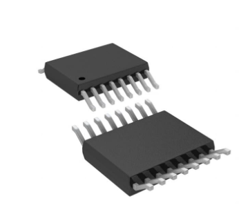


 工商网监
湘ICP备2023018690号
工商网监
湘ICP备2023018690号
