LM2902-EP
www.ti.com
SGLS335A – APRIL 2006 – REVISED APRIL 2006
QUADRUPLE OPERATIONAL AMPLIFIER
FEATURES
•
•
•
•
•
(1)
•
•
•
•
Controlled Baseline
– One Assembly/Test Site, One Fabrication
Site
Extended Temperature Performance of -55°C
to 125°C
Enhanced Diminishing Manufacturing
Sources (DMS) Support
Enhanced Product-Change Notification
Qualification Pedigree
Component qualification in accordance with JEDEC and
industry standards to ensure reliable operation over an
extended temperature range. This includes, but is not limited
to, Highly Accelerated Stress Test (HAST) or biased 85/85,
temperature cycle, autoclave or unbiased HAST,
electromigration, bond intermetallic life, and mold compound
life. Such qualification testing should not be viewed as
justifying use of this component beyond specified
performance and environmental limits.
ESD Protection 2 kV Machine
Model >200 V and Charge Device Model = 2
kV For K-Suffix Devices.
Low Supply-Current Drain Independent of
Supply Voltage . . . 0.8 mA Typ
Low Input Bias and Offset Parameters:
– Input Offset Voltage . . . 3 mV Typ
– Input Offset Current . . . 2 nA Typ
– Input Bias Current . . . 20 nA Typ
•
•
•
•
Common-Mode Input Voltage Range Includes
Ground, Allowing Direct Sensing Near
Ground
Differential Input Voltage Range Equal to
Maximum-Rated Supply Voltage:
– Non-V devices . . . 26 V
– V-Suffix devices . . . 32 V
V-Suffix devices . . . 32 V D Open-Loop
Differential Voltage Amplification . . . 100
V/mV Typ
Internal Frequency Compensation
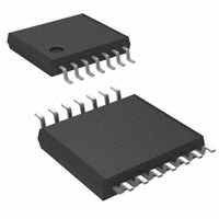
D OR PW PACKAGE
(TOP VIEW)
1OUT
1IN−
1IN+
VCC
2IN+
2IN−
2OUT
1
14
2
13
3
12
4
11
5
10
6
9
7
8
4OUT
4IN−
4IN+
GND
3IN+
3IN−
3OUT
DESCRIPTION
This device consists of four independent high-gain frequency-compensated operational amplifiers that are
designed specifically to operate from a single supply over a wide range of voltages. Operation from split supplies
is possible when the difference between the two supplies is 3 V to 26 V (3 V to 32 V for V-suffixed devices) and
VCC is at least 1.5 V more positive than the input common-mode voltage. The low supply-current drain is
independent of the magnitude of the supply voltage.
Applications include transducer amplifiers, dc amplification blocks, and all the conventional operational-amplifier
circuits that now can be more easily implemented in single-supply voltage systems. For example, the LM2902
can be operated directly from the standard 5-V supply that is used in digital systems and easily provides the
required interface electronics without requiring additional ±15-V supplies.
Please be aware that an important notice concerning availability, standard warranty, and use in critical applications of Texas
Instruments semiconductor products and disclaimers thereto appears at the end of this data sheet.
PRODUCTION DATA information is current as of publication date.
Products conform to specifications per the terms of the Texas
Instruments standard warranty. Production processing does not
necessarily include testing of all parameters.
Copyright © 2006, Texas Instruments Incorporated
�LM2902-EP
www.ti.com
SGLS335A – APRIL 2006 – REVISED APRIL 2006
ORDERING INFORMATION
TA
–40°C to 125°C
VIO max
AT 25°C
MAX VCC
7 mV
26 V
7 mV
3 mV
7 mV
–55°C to 125°C
7 mV
3 mV
(1)
(2)
PACKAGE (1)
32 V
32 V
26 V
32 V
32 V
TOP-SIDE
MARKING
2902EP
SOIC (D)
Reel of 2500
LM2902QDREP (2)
TSSOP(PW)
Reel of 2500
LM2902QPWREP (2)
2902EP
SOIC (D)
Reel of 2500
LM2902KVQDREP (2)
2902KVE
TSSOP(PW)
Reel of 2500
LM2902KVQPWREP (2)
2902KVE
SOIC (D)
Reel of 2500
LM2902KAVQDREP (2)
LM2902E
TSSOP(PW)
Reel of 2500
LM2902KAVQPWREP
LM2902E
SOIC (D)
Reel of 2500
LM2902MDREP (2)
2902ME
TSSOP(PW)
Reel of 2000
LM2902MPWREP (2)
2902ME
SOIC (D)
Reel of 2500
LM2902KVMDREP (2)
2902KME
TSSOP(PW)
Reel of 2000
LM2902KVMPWREP (2)
2902KME
SOIC (D)
Reel of 2500
LM2902KAVMDREP (2)
2902KAE
TSSOP(PW)
Reel of 2000
LM2902KAVMPWREP (2)
2902KAE
Package drawings, standard packing quantities, thermal data, symbolization, and PCB design guidelines are available at
www.ti.com/sc/package.
Product Preview
SYMBOL (EACH AMPLIFIER)
−
IN−
OUT
+
IN+
2
ORDERABLE
PART NUMBER
Submit Documentation Feedback
�LM2902-EP
www.ti.com
SGLS335A – APRIL 2006 – REVISED APRIL 2006
SCHEMATIC (EACH AMPLIFIER)
VCC
≈6-µA
Current
Regulator
≈6-µA
Current
Regulator
≈100-µA
Current
Regulator
OUT
IN−
≈50-µA
Current
Regulator
IN+
GND
To Other
Amplifiers
COMPONENT COUNT
(TOTAL DEVICE)
Epi-FET
Transistors
Diodes
Resistors
Capacitors
1
95
4
11
4
Submit Documentation Feedback
3
�LM2902-EP
www.ti.com
SGLS335A – APRIL 2006 – REVISED APRIL 2006
ABSOLUTE MAXIMUM RATINGS
over operating free-air temperature range (unless otherwise noted) (1)
LM2902-EP
LM2902KV-EP
UNIT
VCC
Supply voltage (2)
26
32
V
VID
Differential input voltage (3)
±26
±32
V
VI
Input voltage (either input)
–0.3 to 26
–0.3 to 32
V
Duration of output short circuit (one amplifier) to ground at (or below) TA = 25°C,
VCC≤ 15 V (4)
Unlimited
Unlimited
D package (0 LFPM)
101
101
PW package
113
113
θJA
Package thermal impedance (5) (6)
TJ
Operating virtual junction temperature
Tstg
Storage temperature range (7)
(1)
(2)
(3)
(4)
(5)
(6)
(7)
4
°C/W
142
142
°C
–65 to 150
–65 to 150
°C
Stresses beyond those listed under absolute maximum ratings may cause permanent damage to the device. These are stress ratings
only, and functional operation of the device at these or any other conditions beyond those indicated under recommended operating
conditions is not implied. Exposure to absolute-maximum-rated conditions for extended periods may affect device reliability.
All voltage values, except differential voltages and VCC specified for the measurement of IOS, are with respect to the network GND.
Differential voltages are at IN+ with respect to IN–.
Short circuits from outputs to VCC can cause excessive heating and eventual destruction.
Maximum power dissipation is a function of TJ(max), θJA, and TA. The maximum allowable power dissipation at any allowable ambient
temperature is PD = (TJ(max) – TA)/θJA. Operating at the absolute maximum TJ of 142°C can affect reliability.
The package thermal impedance is calculated in accordance with JESD 51-7.
Long term high-temperature storage and/or extended use at maximum recommended operating conditions may result in reduction of
overall device life. See http://www.ti.com/ep_quality for additional information on enhanced plastic packaging.
Submit Documentation Feedback
�LM2902-EP
www.ti.com
SGLS335A – APRIL 2006 – REVISED APRIL 2006
ELECTRICAL CHARACTERISTICS
at specified free-air temperature, VCC = 5 V (unless otherwise noted)
PARAMETER
Input offset voltage
VCC = 5 V to 26 V,
VIC = VICRmin, VO = 1.4 V
Input offset current
VO = 1.4 V
IIB
Input bias current
VO = 1.4 V
VICR
Common-mode input voltage
range
VIO
IIO
TA (2)
TEST CONDITIONS (1)
25°C
High-level output voltage
TYP (3)
MAX
3
7
Full range
25°C
2
25°C
VCC = 5 V to 26 V
Full range
25°C
mV
50
nA
300
–20
Full range
25°C
UNIT
10
Full range
RL = 10 kΩ
VOH
LM2902-EP
MIN
–250
nA
–500
0 to
VCC– 1.5
V
0 to
VCC– 2
VCC– 1.5
VCC = 26 V, RL = 2 kΩ
Full range
22
VCC = 26 V, RL ≥ 10 kΩ
25°C
23
V
24
VOL
Low-level output voltage
RL≤ 10 kΩ
Full range
AVD
Large-signal differential voltage
amplification
VCC = 15 V, VO = 1 V to 11 V,
RL≥ 2 kΩ
Full range
15
CMRR
Common-mode rejection ratio
VIC = VICRmin
25°C
50
80
dB
kSVR
Supply-voltage rejection ratio
(∆VCC/∆VIO)
50
100
dB
120
dB
VO1/VO2 Crosstalk attenuation
IO
Output current
25°C
25°C
f = 1 kHz to 20 kHz
VCC = 15 V, VID = 1 V, VO = 0
VCC = 15 V, VID = –1 V, VO = 15 V
ICC
(1)
(2)
(3)
Short-circuit output current
Supply current (four amplifiers)
20
100
25°C
25°C
–20
Full range
–10
25°C
10
Full range
5
VID = –1 V, VO = 200 mV
IOS
5
V/mV
–30
mA
20
25°C
30
mA
µA
25°C
±40
±60
VO = 2.5 V, No load
Full range
0.7
1.2
VCC = 26 V, VO = 0.5 VCC, No load
Full range
1.4
3
VCC at 5 V, VO = 0, GND at –5 V
mV
mA
mA
All characteristics are measured under open-loop conditions, with zero common-mode input voltage, unless otherwise specified.
Full range is –55°C to 125°C.
All typical values are at TA = 25°C.
Submit Documentation Feedback
5
�LM2902-EP
www.ti.com
SGLS335A – APRIL 2006 – REVISED APRIL 2006
ELECTRICAL CHARACTERISTICS
at specified free-air temperature, VCC = 5 V (unless otherwise noted)
PARAMETER
VIO
Input offset voltage
∆VIO/∆T
Temperature drift
IIO
Input offset current
∆VIO/∆T
Temperature drift
IIB
Input bias current
VICR
Common-mode input voltage
range
TA (2)
TEST CONDITIONS (1)
VCC = 5 V to 32 V,
VIC = VICRmin, VO =
1.4 V
Non-A
devices
A-suffix
devices
RS = 0 Ω
25°C
High-level output voltage
Full range
7
25°C
2
VO = 1.4 V
Full range
10
25°C
–20
Full range
25°C
VCC = 5 V to 32 V
Full range
0 to
VCC– 1.5
VCC– 1.5
Full range
26
VCC = 32 V,
RL≥ 10 kΩ
Full range
27
AVD
Large-signal differential
voltage amplification
VCC = 15 V, VO = 1 V to 11 V,
RL≥ 2 kΩ
25°C
25
Full range
15
Amplifier-to-amplifier
coupling (4)
f = 1 kHz to 20 kHz, input referred
CMRR
Common-mode rejection ratio
VIC = VICRmin
kSVR
Supply-voltage rejection ratio
(∆VCC /∆VIO)
VO1/ VO2
Crosstalk attenuation
ICC
Supply current (four
amplifiers)
(1)
(2)
(3)
(4)
20
100
mV
V/mV
120
dB
25°C
60
80
dB
25°C
60
100
dB
120
dB
25°C
25°C
–20
Full range
–10
VCC = 15 V, VID = -1 V, VO = 15 V
V
5
25°C
VO = 0
nA
V
0 to
VCC– 2
RL = 2 kΩ
f = 1 kHz to 20 kHz
nA
pA/°C
–250
–500
VCC = 32 V,
VCC = 15, VID = 1 V,
6
25°C
mV
µV/°C
50
150
Full range
VO = 1.4 V
3
UNIT
4.5
Full range
Short-circuit output current
7
Full range
RL = 10 kΩ
IOS
3
1
Low-level output voltage
Output current
MAX
10
25°C
VOL
IO
TYP (3)
Full range
RL = 10 kΩ
VOH
LM2902KV-EP
MIN
25°C
10
Full range
5
12
–30
mA
20
mA
VID = –1 V,
VO = 200
mV
25°C
VCC at 5 V,
GND at –5 V
VO = 0,
25°C
±40
±60
VO = 2.5 V,
No load
Full range
0.7
1.2
VCC = 32 V,
VO = 0.5 VCC,
No load
Full range
1.4
3
µA
40
mA
mA
All characteristics are measured under open-loop conditions, with zero common-mode input voltage, unless otherwise specified.
Full range is –55°C to 125°C.
All typical values are at TA = 25°C.
Due to proximity of external components, ensure that coupling is not originating via stray capacitance between these external parts.
Typically, this can be detected, as this type of coupling increases at higher frequencies.
Submit Documentation Feedback
�LM2902-EP
www.ti.com
SGLS335A – APRIL 2006 – REVISED APRIL 2006
OPERATING CONDITIONS
VCC = ±15 V, TA = 25°C
PARAMETER
TEST CONDITIONS
TYP
UNIT
SR
Slew rate at unity gain
RL = 1 MΩ, CL = 30 pF, VI = ±10 V (see Figure 1)
0.5
V/µs
B1
Unity-gain bandwidth
RL = 1 MΩ, CL = 20 pF (see Figure 1)
1.2
MHz
Vn
Equivalent input noise voltage
RS = 100 Ω, VI = 0 V, f = 1 kHz (see Figure 2)
35
nV/√Hz
VCC+
−
VI
VO
+
VCC−
CL
RL
Figure 1. Unity-Gain Amplifier
900 Ω
VCC+
100 Ω
−
VI = 0 V
RS
VO
+
VCC−
Figure 2. Noise-Test Circuit
Submit Documentation Feedback
7
�PACKAGE MATERIALS INFORMATION
www.ti.com
3-Jun-2022
TAPE AND REEL INFORMATION
REEL DIMENSIONS
TAPE DIMENSIONS
K0
P1
B0 W
Reel
Diameter
Cavity
A0
B0
K0
W
P1
A0
Dimension designed to accommodate the component width
Dimension designed to accommodate the component length
Dimension designed to accommodate the component thickness
Overall width of the carrier tape
Pitch between successive cavity centers
Reel Width (W1)
QUADRANT ASSIGNMENTS FOR PIN 1 ORIENTATION IN TAPE
Sprocket Holes
Q1
Q2
Q1
Q2
Q3
Q4
Q3
Q4
User Direction of Feed
Pocket Quadrants
*All dimensions are nominal
Device
Package Package Pins
Type Drawing
SPQ
Reel
Reel
A0
Diameter Width (mm)
(mm) W1 (mm)
B0
(mm)
K0
(mm)
P1
(mm)
W
Pin1
(mm) Quadrant
LM2902KAVMPWREP
TSSOP
PW
14
2000
330.0
12.4
6.9
5.6
1.6
8.0
12.0
Q1
LM2902KAVQPWREP
TSSOP
PW
14
2000
330.0
12.4
6.9
5.6
1.6
8.0
12.0
Q1
Pack Materials-Page 1
�PACKAGE MATERIALS INFORMATION
www.ti.com
3-Jun-2022
TAPE AND REEL BOX DIMENSIONS
Width (mm)
W
L
H
*All dimensions are nominal
Device
Package Type
Package Drawing
Pins
SPQ
Length (mm)
Width (mm)
Height (mm)
LM2902KAVMPWREP
TSSOP
PW
14
2000
356.0
356.0
35.0
LM2902KAVQPWREP
TSSOP
PW
14
2000
356.0
356.0
35.0
Pack Materials-Page 2
���IMPORTANT NOTICE AND DISCLAIMER
TI PROVIDES TECHNICAL AND RELIABILITY DATA (INCLUDING DATA SHEETS), DESIGN RESOURCES (INCLUDING REFERENCE
DESIGNS), APPLICATION OR OTHER DESIGN ADVICE, WEB TOOLS, SAFETY INFORMATION, AND OTHER RESOURCES “AS IS”
AND WITH ALL FAULTS, AND DISCLAIMS ALL WARRANTIES, EXPRESS AND IMPLIED, INCLUDING WITHOUT LIMITATION ANY
IMPLIED WARRANTIES OF MERCHANTABILITY, FITNESS FOR A PARTICULAR PURPOSE OR NON-INFRINGEMENT OF THIRD
PARTY INTELLECTUAL PROPERTY RIGHTS.
These resources are intended for skilled developers designing with TI products. You are solely responsible for (1) selecting the appropriate
TI products for your application, (2) designing, validating and testing your application, and (3) ensuring your application meets applicable
standards, and any other safety, security, regulatory or other requirements.
These resources are subject to change without notice. TI grants you permission to use these resources only for development of an
application that uses the TI products described in the resource. Other reproduction and display of these resources is prohibited. No license
is granted to any other TI intellectual property right or to any third party intellectual property right. TI disclaims responsibility for, and you
will fully indemnify TI and its representatives against, any claims, damages, costs, losses, and liabilities arising out of your use of these
resources.
TI’s products are provided subject to TI’s Terms of Sale or other applicable terms available either on ti.com or provided in conjunction with
such TI products. TI’s provision of these resources does not expand or otherwise alter TI’s applicable warranties or warranty disclaimers for
TI products.
TI objects to and rejects any additional or different terms you may have proposed. IMPORTANT NOTICE
Mailing Address: Texas Instruments, Post Office Box 655303, Dallas, Texas 75265
Copyright © 2022, Texas Instruments Incorporated
�


 工商网监
湘ICP备2023018690号
工商网监
湘ICP备2023018690号
