LM3509
www.ti.com
SNVS495D – FEBRUARY 2007 – REVISED MAY 2013
LM3509 High Efficiency Boost for White LED's and/or OLED Displays with Dual Current
Sinks and I2C Compatible Brightness Control
Check for Samples: LM3509
FEATURES
APPLICATIONS
•
•
1
2
•
•
•
•
•
•
•
•
•
•
•
•
•
Integrated OLED Display Power Supply and
LED Driver
Drives up to 10 LED’s at 30mA
Drives up to 5 LED’s at 20mA and Delivers up
to 21V at 40mA
Over 90% Efficient
32 Exponential Dimming Steps
0.15% Accurate Current Matching Between
Strings
Internal Soft-Start Limits Inrush Current
True Shutdown Isolation for LED’s
Wide 2.7V to 5.5V Input Voltage Range
21V Over-Voltage Protection
1.27MHz Fixed Frequency Operation
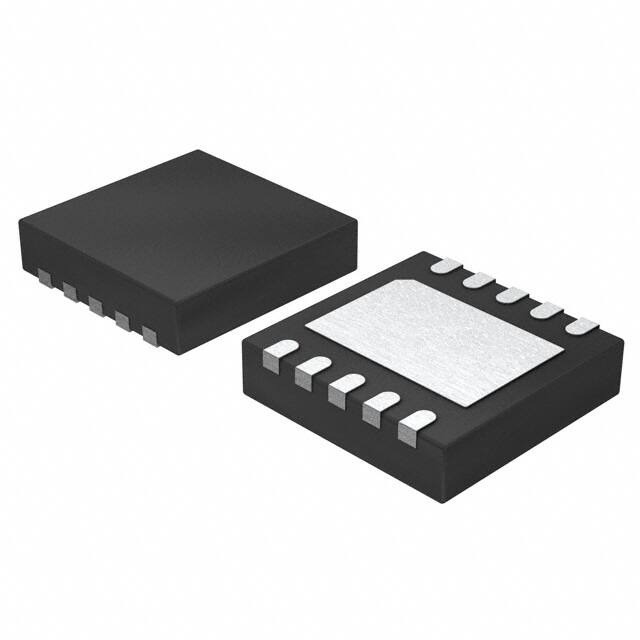
Low Profile 10-Pin WSON Package (3mm x
3mm x 0.8mm)
General Purpose I/O
Active Low Hardware Reset
•
•
Dual Display LCD Backlighting for Portable
Applications
Large Format LCD Backlighting
OLED Panel Power Supply
DESCRIPTION
The LM3509 current mode boost converter offers two
separate outputs. The first output (MAIN) is a
constant current sink for driving series white LED’s.
The second output (SUB/FB) is configurable as a
constant current sink for series white LED bias, or as
a feedback pin to set a constant output voltage for
powering OLED panels.
Typical Application Circuits
10 PH
30 mA per string
2.7V to 5.5V
CIN
IN
1 PF
SW
OVP
LM3509
COUT
1 PF
VIO
10 k:
10 k:
SCL
SDA
MAIN
SUB/FB
RESET/GPIO
SET
GND
RSET
8 k:
Dual White LED Bias Supply
1
2
Please be aware that an important notice concerning availability, standard warranty, and use in critical applications of
Texas Instruments semiconductor products and disclaimers thereto appears at the end of this data sheet.
All trademarks are the property of their respective owners.
PRODUCTION DATA information is current as of publication date.
Products conform to specifications per the terms of the Texas
Instruments standard warranty. Production processing does not
necessarily include testing of all parameters.
Copyright © 2007–2013, Texas Instruments Incorporated
�LM3509
SNVS495D – FEBRUARY 2007 – REVISED MAY 2013
www.ti.com
DESCRIPTION (CONTINUED)
When configured as a dual output white LED bias supply, the LM3509 adaptively regulates the supply voltage of
the LED strings to maximize efficiency and insure the current sinks remain in regulation. The maximum current
per output is set via a single external low power resistor. An I2C compatible interface allows for independent
adjustment of the LED current in either output from 0 to max current in 32 exponential steps. When configured as
a white LED + OLED bias supply the LM3509 can independently and simultaneously drive a string of up to 5
white LED’s and deliver a constant output voltage of up to 21V for OLED panels.
Output over-voltage protection shuts down the device if VOUT rises above 21V allowing for the use of small sized
low voltage output capacitors. The LM3509 is offered in a small 10-pin thermally- enhanced WSON package and
operates over the -40°C to +85°C temperature range.
2
Submit Documentation Feedback
Copyright © 2007–2013, Texas Instruments Incorporated
Product Folder Links: LM3509
�LM3509
www.ti.com
SNVS495D – FEBRUARY 2007 – REVISED MAY 2013
10 PH
2.7V to 5.5V
CIN
VOLED = 18V
SW
IN
1 PF
OVP
COUT
2.2 PF
LM3509
R1
140 k:
20 mA
40 mA
VIO
10 k:
OLED
Display
10 k:
SCL
SDA
MAIN
SUB/FB
RESET/GPIO
SET
R2
10 k:
RSET
12 k:
GND
OLED Panel Power Supply
Connection Diagram
Top View
BOTTOM VIEW
TOP VIEW
1
10
10
1
2
9
9
2
8
8
4
7
7
4
5
6
6
5
3
DAP
DAP
3
Figure 1. 10-Pin WSON (3mm × 3mm × 0.8mm)
PIN DESCRIPTIONS
Pin
Name
1
MAIN
Function
2
SUB/FB
3
SET
LED Current Setting Connection. Connect a resistor from SET to GND to set the maximum LED
current into MAIN or SUB/FB (when in LED mode), where ILED_MAX = 192×1.244V/RSET.
4
VIO
Logic Voltage Level Input
5
RESET/GPIO
6
SW
Drain Connection for Internal NMOS Switch
7
OVP
Over-Voltage Protection Sense Connection. Connect OVP to the positive terminal of the output
capacitor.
8
IN
Main Current Sink Input.
Secondary Current Sink Input or 1.25V Feedback Connection for Constant Voltage Output.
Active Low Hardware Reset and Programmable General Purpose I/O.
Input Voltage Connection. Connect IN to the input supply, and bypass to GND with a 1µF ceramic
capacitor.
Submit Documentation Feedback
Copyright © 2007–2013, Texas Instruments Incorporated
Product Folder Links: LM3509
3
�LM3509
SNVS495D – FEBRUARY 2007 – REVISED MAY 2013
www.ti.com
PIN DESCRIPTIONS (continued)
Pin
Name
9
SDA
Serial Data Input/Output
Function
10
SCL
Serial Clock Input
DAP
GND
Ground
These devices have limited built-in ESD protection. The leads should be shorted together or the device placed in conductive foam
during storage or handling to prevent electrostatic damage to the MOS gates.
Absolute Maximum Ratings (1) (2) (3)
−0.3V to 6V
VIN
VSW, VOVP,
−0.3V to 25V
VSUB/FB, VMAIN
−0.3V to 23V
−0.3V to 6V
VSCL, VSDA, VRESET\GPIO, VIO , VSET
Continuous Power Dissipation
Internally Limited
Junction Temperature (TJ-MAX)
+150ºC
Storage Temperature Range
-65ºC to +150º C
Maximum Lead Temperature (Soldering, 10s) (4)
+300°C
ESD Rating (5)
Human Body Model
(1)
(2)
(3)
(4)
(5)
2.5kV
Absolute maximum ratings are limits beyond which damages to the device may occur. Operating Ratings are conditions for which the
device is intended to be functional, but device parameter specifications may not be ensured. For ensured specifications and test
conditions, see the Electrical Characteristics.
If Military/Aerospace specified devices are required, please contact the Texas Instrument Sales Office/ Distributors for availability and
specifications.
All voltages are with respect to the potential at the GND pin.
For detailed soldering specifications and information, please refer to Application Note 1187: Leadless Lead frame Package (AN-1187)
(Literature Number SNOA401).
The human body model is a 100pF capacitor discharged through 1.5kΩ resistor into each pin. (MIL-STD-883 3015.7).
Operating Ratings (1) (2)
VIN
2.7V to 5.5V
VSW, VOVP,
0V to 23V
VSUB/FB, VMAIN
0V to 21V
(3)
-40ºC to +110ºC
Ambient Temperature Range (TA) (4)
-40ºC to +85ºC
Junction Temperature Range (TJ)
(1)
(2)
(3)
(4)
Absolute maximum ratings are limits beyond which damages to the device may occur. Operating Ratings are conditions for which the
device is intended to be functional, but device parameter specifications may not be ensured. For ensured specifications and test
conditions, see the Electrical Characteristics.
All voltages are with respect to the potential at the GND pin.
Internal thermal shutdown circuitry protects the device from permanent damage. Thermal shutdown engages at TJ=150ºC (typ.) and
disengages at TJ=140ºC (typ.).
In applications where high power dissipation and/or poor package thermal resistance is present, the maximum ambient temperature may
have to be derated. Maximum ambient temperature (TA-MAX) is dependent on the maximum operating junction temperature (TJ-MAX-OP
= +105ºC), the maximum power dissipation of the device in the application (PD-MAX), and the junction-to ambient thermal resistance of
the part/package in the application (θJA), as given by the following equation: TA-MAX = TJ-MAX-OP – (θJA × PD-MAX).
Thermal Properties
Junction to Ambient Thermal Resistance (θJA) (1)
(1)
4
54°C/W
Junction-to-ambient thermal resistance (θJA) is taken from a thermal modeling result, performed under the conditions and guidelines set
forth in the JEDEC standard JESD51-7. The test board is a 4-layer FR-4 board measuring 114mm x 76mm x 1.6mm with a 2x1 array of
thermal vias. The ground plane on the board is 113mm x 75mm. Thickness of copper layers are 71.5µm/35µm/35µm/71.5µm
(2oz/1oz/1oz/2oz). Ambient temperature in simulation is 22°C, still air. Power dissipation is 1W. The value of θJA of this product in the
WSON package could fall in a range as wide as 50ºC/W to 150ºC/W (if not wider), depending on board material, layout, and
environmental conditions. In applications where high maximum power dissipation exists special care must be paid to thermal dissipation
issues. For more information on these topics, please refer to Application Note 1187: Leadless Leadframe Package (LLP) (Literature
Number SNOA401).
Submit Documentation Feedback
Copyright © 2007–2013, Texas Instruments Incorporated
Product Folder Links: LM3509
�LM3509
www.ti.com
SNVS495D – FEBRUARY 2007 – REVISED MAY 2013
Electrical Characteristics
Specifications in standard type face are for TA = 25°C and those in boldface type apply over the Operating Temperature
Range of TA = −40°C to +85°C. Unless otherwise specified VIN = 3.6V, VIO = 1.8V, VRESET/GPIO = VIN, VSUB/FB = VMAIN = 0.5V,
R = 12.0kΩ, OLED = ‘0’, ENM = ENS = ‘1’, BSUB = BMAIN = Full Scale. (1) (2)
SET
Symbol
ILED
Parameter
Conditions
Output Current Regulation
MAIN or SUB/FB Enabled
UNI = ‘0’, or ‘1’
Maximum Current Per
Current Sink
RSET = 8.0kΩ
Min
18.6
Typ
Max
20
21.8
30
Units
mA
(3)
ILED-MATCH
IMAIN to ISUB/FB Current
Matching
UNI = ‘1’
VSET
SET Pin Voltage
3.0V < VIN < 5V
ILED/ISET
ILED Current to ISET Current
Ratio
192
VREG_CS
Regulated Current Sink
Headroom Voltage
500
VREG_OLED
VSUB/FB Regulation Voltage in 3.0V < VIN < 5.5V, OLED =
OLED Mode
‘1’
VHR
Current Sink Minimum
Headroom Voltage
RDSON
NMOS Switch On Resistance ISW = 100mA
ICL
NMOS Switch Current Limit
VIN = 3.0V
650
VOVP
Output Over-Voltage
Protection
ON Threshold
OFF Threshold
0.15
1
%
1.244
1.172
ILED = 95% of nominal
1.21
V
mV
1.239
300
V
mV
Ω
0.58
770
875
21.2
22
22.9
19.7
20.6
21.2
1.0
1.27
1.4
mA
V
fSW
Switching Frequency
DMAX
Maximum Duty Cycle
90
%
DMIN
Minimum Duty Cycle
10
%
IQ
Quiescent Current, Device
Not Switching
ISHDN
Shutdown Current
MHz
VMAIN and VSUB/FB >
VREG_CS, BSUB = BMAIN =
0x00
400
VSUB/FB > VREG_OLED,
OLED=’1’, ENM=ENS=’0’
250
305
ENM = ENS = OLED = '0'
3.6
5
µA
0.5
V
440
µA
RESET/GPIO Pin Voltage Specifications
VIL
Input Logic Low
2.7V < VIN
0.3V.
Input Capacitor Selection
Choosing the correct size and type of input capacitor helps minimize the input voltage ripple caused by the
switching of the LM3509’s boost converter. For continuous inductor current operation the input voltage ripple is
composed of 2 primary components, the capacitor discharge (delta VQ) and the capacitor’s equivalent series
resistance (delta VESR). These ripple components are found by:
'VQ =
'I L x D
2 x f SW x C IN
and
'VESR = 2 x 'I L x R ESR
where 'I L =
VIN x (VOUT - VIN )
2 x f SW x L x VOUT
(6)
In the typical application circuit a 1µF ceramic input capacitor works well. Since the ESR in ceramic capacitors is
typically less than 5mΩ and the capacitance value is usually small, the input voltage ripple is primarily due to the
capacitive discharge. With larger value capacitors such as tantalum or aluminum electrolytic the ESR can be
greater than 0.5Ω. In this case the input ripple will primarily be due to the ESR.
Output Capacitor Selection
The LM3509’s output capacitor supplies the LED current during the boost converters on time. When the switch
turns off the inductor energy is discharged through the diode supplying power to the LED’s and restoring charge
to the output capacitor. This causes a sag in the output voltage during the on time and a rise in the output
voltage during the off time. The output capacitor is therefore chosen to limit the output ripple to an acceptable
level depending on LED or OLED panel current requirements and input/output voltage differentials. For proper
operation ceramic output capacitors ranging from 1µF to 2.2µF are required.
As with the input capacitor, the output voltage ripple is composed of two parts, the ripple due to capacitor
discharge (delta VQ) and the ripple due to the capacitors ESR (delta VESR). For continuous conduction mode, the
ripple components are found by:
Submit Documentation Feedback
Copyright © 2007–2013, Texas Instruments Incorporated
Product Folder Links: LM3509
21
�LM3509
SNVS495D – FEBRUARY 2007 – REVISED MAY 2013
'VQ =
ILED u (VOUT
VIN)
and
fSW u VOUT u COUT
'VESR = RESR u
where
www.ti.com
§ ILED u VOUT
·
+ 'IL¸
¨ VIN
©
¹
'IL =
VIN u (VOUT
VIN)
2 u fSW u L u VOUT
(7)
Table 7 lists different manufacturers for various capacitors and their case sizes that are suitable for use with the
LM3509. When configured as a dual output LED driver a 1µF output capacitor is adequate. In OLED mode for
output voltages above 12V a 2.2µF output capacitor is required.
Table 7. Recommended Output Capacitors
Manufacturer
Part Number
Value
Case Size
Voltage Rating
TDK
C1608X5R1E105M
1µF
0603
25V
Murata
GRM39X5R105K25D539
1µF
0603
25V
TDK
C2012X5R1E225M
2.2µF
0805
25V
Murata
GRM219R61E225KA12
2.2µF
0805
25V
Inductor Selection
The LM3509 is designed for use with a 10µH inductor, however 22µH are suitable providing the output capacitor
is increased 2×'s. When selecting the inductor ensure that the saturation current rating (ISAT) for the chosen
inductor is high enough and the inductor is large enough such that at the maximum LED current the peak
inductor current is less than the LM3509’s peak switch current limit. This is done by choosing:
ISAT >
'IL =
I LED VOUT
+ 'I L
×
K
VIN
VIN x (VOUT - VIN )
2 x f SW x L x VOUT
where
, and
VIN x (VOUT - VIN)
L>
§
2 x f SW x VOUT x ¨
¨I PEAK -
I LED _ MAX x VOUT ·
©
K x VIN
¸¸
¹
(8)
Values for IPEAK can be found in the plot of peak current limit vs. VIN in the Typical Performance Characteristics
graphs. Table 8 shows possible inductors, as well as their corresponding case size and their saturation current
ratings.
Table 8. Recommended Inductors
22
Manufacturer
Part Number
Value
Dimensions
ISAT
DC Resistance
TDK
VLF3012AT100MR49
10µH
2.6mm×2.8mm×1m
m
490mA
0.36Ω
TDK
VLF4012AT100MR79
10µH
3.5mm×3.7mm×1.2
mm
800mA
0.3Ω
TOKO
A997AS-100M
10µH
3.8mm×3.8mm×1.8
mm
580mA
0.18Ω
Submit Documentation Feedback
Copyright © 2007–2013, Texas Instruments Incorporated
Product Folder Links: LM3509
�LM3509
www.ti.com
SNVS495D – FEBRUARY 2007 – REVISED MAY 2013
Diode Selection
The output diode must have a reverse breakdown voltage greater than the maximum output voltage. The diodes
average current rating should be high enough to handle the LM3509’s output current. Additionally, the diodes
peak current rating must be high enough to handle the peak inductor current. Schottky diodes are recommended
due to their lower forward voltage drop (0.3V to 0.5V) compared to (0.6V to 0.8V) for PN junction diodes. If a PN
junction diode is used, ensure it is the ultra-fast type (trr < 50ns) to prevent excessive loss in the rectifier. For
Schottky diodes the B05030WS (or equivalent) work well for most designs. See Table 9 for a list of other
Schottky Diodes with similar performance.
Table 9. Recommended Schottky Diodes
Manufacturer
Part Number
Package
Reverse Breakdown Voltage
Average Current Rating
Diodes Inc.
B05030WS
SOD-323
30V
0.5A
Philips
BAT760
SOD-323
23V
1A
ON Semiconductor
NSR0320MW2T
SOD-323
30V
1A
Output Current Range (OLED Mode)
The maximum output current the LM3509 can deliver in OLED mode is limited by 4 factors (assuming continuous
conduction); the peak current limit of 770mA (typical), the inductor value, the input voltage, and the output
voltage. Calculate the maximum output current (IOUT_MAX) using the following equation:
(IPEAK
IOUT_MAX =
where
'IL =
'IL) u K u VIN
VOUT
VIN u (VOUT
VIN)
2 u fSW u L u VOUT
(9)
For the typical application circuit with VOUT = 18V and assuming 70% efficiency, the maximum output current at
VIN = 2.7V will be approximately 70mA. At 4.2V due to the shorter on times and lower average input currents the
maximum output current (at 70% efficiency) jumps to approximately 105mA. Figure 47 shows a plot of IOUT_MAX
vs. VIN using the above equation, assuming 80% efficiency. In reality factors such as current limit and efficiency
will vary over VIN, temperature, and component selection. This can cause the actual IOUT_MAX to be higher or
lower.
Figure 47. Typical Maximum Output Current in OLED Mode
Submit Documentation Feedback
Copyright © 2007–2013, Texas Instruments Incorporated
Product Folder Links: LM3509
23
�LM3509
SNVS495D – FEBRUARY 2007 – REVISED MAY 2013
www.ti.com
Output Voltage Range (OLED Mode)
The LM3509's output voltage is constrained by 2 factors. On the low end it is limited by the minimum duty cycle
of 10% (assuming continuous conduction) and on the high end it is limited by the over voltage protection
threshold (VOVP) of 22V (typical). In order to maintain stability when operating at different output voltages the
output capacitor and inductor must be changed. Refer to Table 10 for different VOUT, COUT, and L combinations.
Table 10. Component Values for Output Voltage Selection
VOUT
COUT
L
VIN Range
18V
2.2µF
10µH
2.7V to 5.5V
15V
2.2µF
10µH
2.7V to 5.5V
12V
4.7µF
10µH
2.7V to 5.5V
9V
10µF
10µH
2.7V to 5.5V
7V
10µF
4.7µH
2.7V to 5.5V
5V
22µF
4.7µH
2.7V to 4.5V
Layout Considerations
The WSON is a leadless package with very good thermal properties. This package has an exposed DAP (die
attach pad) at the underside center of the package measuring 1.6mm x 2.0mm. The main advantage of this
exposed DAP is to offer low thermal resistance when soldered to the thermal ground pad on the PCB. For good
PCB layout a 1:1 ratio between the package and the PCB thermal land is recommended. To further enhance
thermal conductivity, the PCB thermal ground pad may include vias to a 2nd layer ground plane. For more
detailed instructions on mounting WSON packages, please refer to Texas Instrument Application Note AN-1187
(Literature Number SNOA401).
The high switching frequencies and large peak currents make the PCB layout a critical part of the design. The
proceeding steps must be followed to ensure stable operation and proper current source regulation.
1. Divide ground into two planes, one for the return terminals of COUT, CIN and the I2C Bus, the other for the
return terminals of RSET and the feedback network. Connect both planes to the exposed PAD, but nowhere
else.
2. Connect the inductor and the anode of D1 as close together as possible and place this connection as close
as possible to the SW pin. This reduces the inductance and resistance of the switching node which
minimizes ringing and excess voltage drops. This will improve efficiency and decrease noise that can get
injected into the current sources.
3. Connect the return terminals of the input capacitor and the output capacitor as close as possible to the
exposed PAD and through low impedance traces.
4. Bypass IN with at least a 1µF ceramic capacitor. Connect the positive terminal of this capacitor as close as
possible to IN.
5. Connect COUT as close as possible to the cathode of D1. This reduces the inductance and resistance of the
output bypass node which minimizes ringing and the excess voltage drops. This will improving efficiency and
decrease noise that can get injected into the current sources.
6. Route the traces for RSET and the feedback divider away from the SW node to minimize noise injection.
7. Do not connect any external capacitance to the SET pin.
24
Submit Documentation Feedback
Copyright © 2007–2013, Texas Instruments Incorporated
Product Folder Links: LM3509
�LM3509
www.ti.com
SNVS495D – FEBRUARY 2007 – REVISED MAY 2013
REVISION HISTORY
Changes from Revision C (May 2013) to Revision D
•
Page
Changed layout of National Data Sheet to TI format .......................................................................................................... 24
Submit Documentation Feedback
Copyright © 2007–2013, Texas Instruments Incorporated
Product Folder Links: LM3509
25
�PACKAGE OPTION ADDENDUM
www.ti.com
10-Dec-2020
PACKAGING INFORMATION
Orderable Device
Status
(1)
Package Type Package Pins Package
Drawing
Qty
Eco Plan
(2)
Lead finish/
Ball material
MSL Peak Temp
Op Temp (°C)
Device Marking
(3)
(4/5)
(6)
LM3509SD/NOPB
ACTIVE
WSON
DSC
10
1000
RoHS & Green
SN
Level-3-260C-168 HR
-40 to 85
L3509
LM3509SDE/NOPB
ACTIVE
WSON
DSC
10
250
RoHS & Green
SN
Level-3-260C-168 HR
-40 to 85
L3509
LM3509SDX/NOPB
ACTIVE
WSON
DSC
10
4500
RoHS & Green
SN
Level-3-260C-168 HR
-40 to 85
L3509
(1)
The marketing status values are defined as follows:
ACTIVE: Product device recommended for new designs.
LIFEBUY: TI has announced that the device will be discontinued, and a lifetime-buy period is in effect.
NRND: Not recommended for new designs. Device is in production to support existing customers, but TI does not recommend using this part in a new design.
PREVIEW: Device has been announced but is not in production. Samples may or may not be available.
OBSOLETE: TI has discontinued the production of the device.
(2)
RoHS: TI defines "RoHS" to mean semiconductor products that are compliant with the current EU RoHS requirements for all 10 RoHS substances, including the requirement that RoHS substance
do not exceed 0.1% by weight in homogeneous materials. Where designed to be soldered at high temperatures, "RoHS" products are suitable for use in specified lead-free processes. TI may
reference these types of products as "Pb-Free".
RoHS Exempt: TI defines "RoHS Exempt" to mean products that contain lead but are compliant with EU RoHS pursuant to a specific EU RoHS exemption.
Green: TI defines "Green" to mean the content of Chlorine (Cl) and Bromine (Br) based flame retardants meet JS709B low halogen requirements of


 工商网监
湘ICP备2023018690号
工商网监
湘ICP备2023018690号

