Order
Now
Product
Folder
Support &
Community
Tools &
Software
Technical
Documents
LM36010
SNVSAN4B – APRIL 2017 – REVISED OCTOBER 2017
LM36010 Synchronous-Boost, Single-LED Flash Driver
With 1.5-A High-Side Current Source
1 Features
3 Description
•
The LM36010 is an ultra-small LED flash driver that
provides a high level of adjustability. With a total
solution size of 7 mm2, it can produce up to 1.5 A of
LED flash current or up to 376 mA of torch current.
1
•
•
•
•
•
•
•
Accurate and Programmable LED Currents
– Flash / IR Currents Ranging from 11 mA up to
1.5 A (128 Levels)
– Torch Currents Ranging from 2.4 mA up to
376 mA (128 Levels)
Flash Time-Out up to 1.6 Seconds
Optimized Flash LED Current During Low Battery
Conditions (IVFM)
Grounded Cathode LED Operation for Improved
Thermal Management
Small Total Solution Size: < 7 mm2
Hardware Strobe Enable (STROBE)
Input Voltage Range from 2.5 V to 5.5 V
400-kHz I2C-Compatible Interface
– I2C Address = 0x64
2 Applications
•
•
•
•
•
•
Mobile Phones
Tablets
IR LED Driver
Video Surveillance: IP Camera
Barcode Scanner
Portable Data Terminal
The device utilizes a 2-MHz or 4-MHz fixedfrequency, synchronous boost converter to power the
1.5-A constant current LED source. An adaptive
regulation method ensures the current source
remains in regulation and maximizes efficiency as it
controls the current from 11 mA up to 1.5 A in flash
mode or from 2.4 mA up to 376 mA in torch mode.
Features of the LM36010 are controlled via an I2Ccompatible interface. These features include:
hardware flash (STROBE) and 128 programmable
currents for both flash and movie mode (torch). The
2-MHz or 4-MHz switching frequency, overvoltage
protection (OVP), and adjustable current limit allow
for the use of tiny, low-profile inductors and ceramic
capacitors. The device operates over a –40°C to
+85°C ambient temperature range.
Device Information(1)
PART NUMBER
LM36010
PACKAGE
DSBGA (8)
BODY SIZE (NOM)
1.512 mm × 0.800 mm
(1) For all available packages, see the orderable addendum at
the end of the data sheet.
Simplified Schematic
L1
VIN
2.5 V ± 5.5 V
IN
C1
SW
OUT
C2
SDA
µP/µC
SCL
LED
D1
STROBE
GND
Copyright © 2016, Texas Instruments Incorporated
1
An IMPORTANT NOTICE at the end of this data sheet addresses availability, warranty, changes, use in safety-critical applications,
intellectual property matters and other important disclaimers. PRODUCTION DATA.
�LM36010
SNVSAN4B – APRIL 2017 – REVISED OCTOBER 2017
www.ti.com
Table of Contents
1
2
3
4
5
6
7
Features ..................................................................
Applications ...........................................................
Description .............................................................
Revision History.....................................................
Pin Configuration and Functions .........................
Specifications.........................................................
1
1
1
2
3
4
6.1
6.2
6.3
6.4
6.5
6.6
6.7
6.8
4
4
4
4
5
5
5
7
Absolute Maximum Ratings ......................................
ESD Ratings..............................................................
Recommended Operating Conditions.......................
Thermal Information ..................................................
Electrical Characteristics...........................................
Timing Requirements ................................................
Switching Characteristics ..........................................
Typical Characteristics ..............................................
Detailed Description ............................................ 12
7.1
7.2
7.3
7.4
Overview .................................................................
Functional Block Diagram ......................................
Feature Description ................................................
Device Functioning Modes......................................
12
13
14
16
7.5 Programming........................................................... 18
7.6 Register Descriptions .............................................. 20
8
Applications and Implementation ...................... 22
8.1 Application Information............................................ 22
8.2 Typical Application ................................................. 22
9 Power Supply Recommendations...................... 33
10 Layout................................................................... 33
10.1 Layout Guidelines ................................................. 33
10.2 Layout Example ................................................... 34
11 Device and Documentation Support ................. 35
11.1
11.2
11.3
11.4
11.5
11.6
11.7
Device Support......................................................
Documentation Support ........................................
Receiving Notification of Documentation Updates
Community Resources..........................................
Trademarks ...........................................................
Electrostatic Discharge Caution ............................
Glossary ................................................................
35
35
35
35
35
35
35
12 Mechanical, Packaging, and Orderable
Information ........................................................... 35
4 Revision History
Changes from Revision A (July 2017) to Revision B
•
Corrected package dimensions ........................................................................................................................................... 35
Changes from Original (April 2017) to Revision A
•
2
Page
Page
Changed device status from Advance Information to Production Data ................................................................................. 1
Submit Documentation Feedback
Copyright © 2017, Texas Instruments Incorporated
Product Folder Links: LM36010
�LM36010
www.ti.com
SNVSAN4B – APRIL 2017 – REVISED OCTOBER 2017
5 Pin Configuration and Functions
YKB Package
8-Pin DSBGA
Top View
A1
A2
Pin A1
B1
B2
C1
C2
D1
D2
Pin Functions
PIN
TYPE (1)
DESCRIPTION
NAME
NO.
A1
GND
G
Ground
A2
IN
P
Input voltage connection. Connect IN to the input supply and bypass to GND with a 10-µF or
larger ceramic capacitor.
B1
SW
P
Drain connection for Internal NMOS and synchronous PMOS switches.
B2
STROBE
I
Active high hardware flash enable. Drive STROBE high to turn on flash pulse. An internal
pulldown resistor of 300 kΩ is between STROBE and GND.
C1
OUT
P
Step-up DC-DC converter output. Connect a 10-µF ceramic capacitor between this terminal
and GND.
C2
SDA
I/O
D1
LED
P
High-side current source output for flash LED.
D2
SCL
I
I2C serial clock input.
(1)
I2C serial data input/output.
G = Ground; P = Power; I = Input; O = Output
Submit Documentation Feedback
Copyright © 2017, Texas Instruments Incorporated
Product Folder Links: LM36010
3
�LM36010
SNVSAN4B – APRIL 2017 – REVISED OCTOBER 2017
www.ti.com
6 Specifications
6.1 Absolute Maximum Ratings
over operating free-air temperature range (unless otherwise noted) (1) (2)
MIN
MAX
IN, SW, OUT, LED
−0.3
6
SDA, SCL, STROBE
−0.3
(VIN+ 0.3) w/ 6 V maximum
Continuous power dissipation (3)
−65
Storage temperature, Tstg
(2)
(3)
V
Internally limited
Junction temperature, TJ-MAX
(1)
UNIT
150
°C
150
°C
Stresses beyond those listed under Absolute Maximum Ratings may cause permanent damage to the device. These are stress ratings
only, which do not imply functional operation of the device at these or any other conditions beyond those indicated under Recommended
Operating Conditions. Exposure to absolute-maximum-rated conditions for extended periods may affect device reliability.
All voltages are with respect to the potential at the GND pin.
Internal thermal shutdown circuitry protects the device from permanent damage. Thermal shutdown engages at TJ = 150°C (typical) and
disengages at TJ = 135°C (typical). Thermal shutdown is ensured by design.
6.2 ESD Ratings
VALUE
V(ESD)
(1)
(2)
Electrostatic discharge
Human-body model (HBM), per ANSI/ESDA/JEDEC JS-001 (1)
±1000
Charged-device model (CDM), per JEDEC specification JESD22-C101 (2)
±250
UNIT
V
JEDEC document JEP155 states that 500-V HBM allows safe manufacturing with a standard ESD control process.
JEDEC document JEP157 states that 250-V CDM allows safe manufacturing with a standard ESD control process.
6.3 Recommended Operating Conditions
over operating free-air temperature range (unless otherwise noted) (1) (2)
VIN
Junction temperature, TJ
Ambient temperature, TA
(1)
(2)
(3)
(3)
MIN
MAX
2.5
5.5
UNIT
V
−40
125
°C
−40
85
°C
Stresses beyond those listed under absolute maximum ratings may cause permanent damage to the device. These are stress ratings
only, and functional operation of the device at these or any other conditions beyond those indicated under recommended operating
conditions is not implied. Exposure to absolute-maximum-rated conditions for extended periods may affect device reliability.
All voltages are with respect to the potential at the GND pin.
In applications where high power dissipation and/or poor package thermal resistance is present, the maximum ambient temperature may
have to be derated. Maximum ambient temperature (TA-MAX) is dependent on the maximum operating junction temperature (TJ-MAX-OP =
125°C), the maximum power dissipation of the device in the application (PD-MAX), and the junction-to-ambient thermal resistance of the
part/package in the application (RθJA), as given by the following equation: TA-MAX = TJ-MAX-OP – (RθJA × PD-MAX).
6.4 Thermal Information
LM36010
THERMAL METRIC (1)
YKB (DSBGA)
UNIT
8 PINS
RθJA
Junction-to-ambient thermal resistance
117.3
°C/W
RθJC(top)
Junction-to-case (top) thermal resistance
1.3
°C/W
RθJB
Junction-to-board thermal resistance
34.3
°C/W
ΨJT
Junction-to-top characterization parameter
0.5
°C/W
ΨJB
Junction-to-board characterization parameter
34.6
°C/W
(1)
4
For more information about traditional and new thermal metrics, see the Semiconductor and IC Package Thermal Metrics application
report.
Submit Documentation Feedback
Copyright © 2017, Texas Instruments Incorporated
Product Folder Links: LM36010
�LM36010
www.ti.com
SNVSAN4B – APRIL 2017 – REVISED OCTOBER 2017
6.5 Electrical Characteristics
TA = 25°C and VIN = 3.6 V, unless otherwise specified. Minimum and maximum limits apply over the full operating ambient
temperature range (–40°C ≤ TA ≤ 85°C). (1) (2)
PARAMETER
TEST CONDITIONS
MIN
TYP
MAX
UNIT
CURRENT SOURCE SPECIFICATIONS
ILED
Current source accuracy
VHR
LED current source regulation
voltage
VOVP
Overvoltage Protection
(3)
–10%
1.5
10%
A
VOUT = 4 V , torch code = 0x7F = 376 mA
–10%
376
10%
mA
VOUT = 4 V , flash code = 0x7F = 1.5 A
ILED = 1.5 A
Flash
550
ILED = 376 mA
Torch
350
mV
ON threshold
4.86
5
5.10
OFF threshold
4.71
4.85
4.95
V
STEP-UP DC-DC CONVERTER SPECIFICATIONS
RPMOS
PMOS switch on-resistance
175
RNMOS
NMOS switch on-resistance
130
ICL
Switch current limit
VUVLO
Undervoltage lockout threshold
Falling VIN
VIVFM
Input voltage flash monitor trip
threshold
Reg 0x02, bits [7:5] = 000
IQ
Quiescent supply current
Device not switching, in pass mode
0.3
Standby supply current
Device disabled
2.5 V ≤ VIN ≤ 5.5 V
0.8
ISB
mΩ
Reg 0x01, bit [5] = 0
–15%
1.9
15%
Reg 0x01, bit [5] = 1
–15%
2.8
15%
A
2.5
–3%
2.9
V
3%
V
mA
4
µA
0
0.4
V
1.2
VIN
V
STROBE VOLTAGE SPECIFICATIONS
VIL
Input logic low
VIH
Input logic high
2.5 V ≤ VIN ≤ 5.5 V
2
I C-COMPATIBLE INTERFACE SPECIFICATIONS (SCL, SDA)
VIL
Input logic low
VIH
Input logic high
VOL
Output logic low
(1)
(2)
(3)
2.5 V ≤ VIN ≤ 4.2 V
0
0.4
1.2
VIN
ILOAD = 3 mA
V
400
mV
Minimum (MIN) and Maximum (MAX) limits are specified by design, test, or statistical analysis. Typical (TYP) numbers are not verified,
but do represent the most likely norm. Unless otherwise specified, conditions for typical specifications are: VIN = 3.6 V and TA = 25°C.
All voltages are with respect to the potential at the GND pin.
The ability to deliver 1.5 A of LED current is highly dependent upon the input voltage, LED voltage, ambient temperature and PCB
layout. Depending upon the system conditions, it is possible that the device could hit the internal thermal shutdown or thermal scaleback value before the desired flash duration is reached. See Thermal Performance for more details.
6.6 Timing Requirements
MIN
NOM
MAX
UNIT
t1
SCL clock period
2.4
µs
t2
Data in set-up time to SCL high
100
ns
t3
Data out stable after SCL low
0
ns
t4
SDA low set-up time to SCL low (start)
100
ns
t5
SDA high hold time after SCL high (stop)
100
ns
6.7 Switching Characteristics
over operating free-air temperature range (unless otherwise noted)
PARAMETER
ƒSW
Switching frequency
TEST CONDITIONS
2.5 V ≤ VIN ≤ 5.5 V
MIN
TYP
MAX
-10%
2
10%
-10%
4
10%
UNIT
MHz
Submit Documentation Feedback
Copyright © 2017, Texas Instruments Incorporated
Product Folder Links: LM36010
5
�LM36010
SNVSAN4B – APRIL 2017 – REVISED OCTOBER 2017
www.ti.com
t1
SCL
t5
t4
SDA_IN
t2
SDA_OUT
t3
Figure 1. I2C-Compatible Interface Specifications
6
Submit Documentation Feedback
Copyright © 2017, Texas Instruments Incorporated
Product Folder Links: LM36010
�LM36010
www.ti.com
SNVSAN4B – APRIL 2017 – REVISED OCTOBER 2017
6.8 Typical Characteristics
TA = 25°C, VIN = 3.6 V, CIN = 10 µF, COUT = 10 µF, L = 1 µH, VLED = 3.4 V, Flash Time-out = 320 ms and Thermal Scale-Back
(TSB) disabled, unless otherwise noted.
1.5
1.5
85qC
25qC
-40qC
1.2
0.9
IFLASH (A)
IFLASH (A)
1.2
0.6
0.3
0.9
0.6
0.3
0
0x00
0x0F
0x1F
0x2F 0x3F 0x4F 0x5F
Brightness Code (hex)
ƒSW = 2 MHz
0x6F
0
0x00
0x7F
0x0F
0x1F
D001
ICL = 2.8 A
0x2F 0x3F 0x4F 0x5F
Brightness Code (hex)
ƒSW = 4 MHz
Figure 2. LED Flash Current vs Brightness Code
0x6F
0x7F
D002
ICL = 2.8 A
Figure 3. LED Flash Current vs Brightness Code
1.6
0.8
Code 0x00
Code 0x07
Code 0x0F
Code 0x17
Code 0x1F
Code 0x27
Code 0x2F
Code 0x37
Code 0x3F
0.6
0.5
0.4
Code 0x47
Code 0x4F
Code 0x57
Code 0x5F
Code 0x67
Code 0x6F
Code 0x77
Code 0x7F
1.5
1.4
IFLASH (A)
0.7
IFLASH (A)
85qC
25qC
-40qC
0.3
1.3
1.2
1.1
1
0.2
0.9
0.1
0
2.5
0.8
2.5
3
3.5
ƒSW = 2 MHz
4
VIN (V)
4.5
5
D003
ƒSW = 2 MHz
ICL = 2.8 A
4
VIN (V)
4.5
5
5.5
D004
ICL = 2.8 A
Figure 5. LED Flash Current vs Input Voltage
Figure 4. LED Flash Current vs Input Voltage
1.6
1.52
1.52
1.44
1.44
1.36
1.36
1.28
1.28
IFLASH (A)
IFLASH (A)
3.5
.
1.6
1.2
1.12
1.04
1.2
1.12
1.04
0.96
0.96
85qC
25qC
-40qC
0.88
0.8
2.5
3
5.5
3
ƒSW = 2 MHz
ICL = 1.9 A
3.5
4
VIN (V)
4.5
5
85qC
25qC
-40qC
0.88
5.5
0.8
2.5
3
D005
IFLASH = 1.5 A
Flash Time-out < 120 ms at 85°C
Figure 6. LED Flash Current vs Input Voltage
ƒSW = 4 MHz
ICL = 1.9 A
3.5
4
VIN (V)
4.5
5
5.5
D006
IFLASH = 1.5 A
Flash Time-out < 120 ms at 85°C
Figure 7. LED Flash Current vs Input Voltage
Submit Documentation Feedback
Copyright © 2017, Texas Instruments Incorporated
Product Folder Links: LM36010
7
�LM36010
SNVSAN4B – APRIL 2017 – REVISED OCTOBER 2017
www.ti.com
Typical Characteristics (continued)
1.28
1.28
1.24
1.24
1.2
1.2
1.16
1.16
1.12
1.12
IFLASH (A)
IFLASH (A)
TA = 25°C, VIN = 3.6 V, CIN = 10 µF, COUT = 10 µF, L = 1 µH, VLED = 3.4 V, Flash Time-out = 320 ms and Thermal Scale-Back
(TSB) disabled, unless otherwise noted.
1.08
1.04
1.08
1.04
1
1
0.96
0.96
85qC
25qC
-40qC
0.92
0.88
2.5
3
3.5
ƒSW = 2 MHz
ICL = 1.9 A
4
VIN (V)
4.5
5
0.88
2.5
5.5
IFLASH = 1.2 A
Flash Time-out < 280 ms at 85°C
1.06
1.04
1.04
1.02
1.02
1
IFLASH (A)
IFLASH (A)
1.06
0.98
0.96
4.5
5
5.5
D008
IFLASH = 1.2 A
Flash Time-out < 280 ms at 85°C
1
0.98
0.96
0.94
0.92
0.92
85qC
25qC
-40qC
0.9
3
3.5
ƒSW = 2 MHz
4
VIN (V)
4.5
5
85qC
25qC
-40qC
0.9
0.88
2.5
5.5
3
3.5
D009
IFLASH = 1.03 A
ICL = 1.9 A
ƒSW = 4 MHz
Figure 10. LED Flash Current vs Input Voltage
4
VIN (V)
4.5
5
5.5
D010
IFLASH = 1.03 A
ICL = 1.9 A
Figure 11. LED Flash Current vs Input Voltage
1.08
1.08
1.06
1.06
1.04
1.04
1.02
1.02
1
IFLASH (A)
IFLASH (A)
4
VIN (V)
Figure 9. LED Flash Current vs Input Voltage
1.08
0.94
0.98
0.96
0.94
1
0.98
0.96
0.94
0.92
0.92
85qC
25qC
-40qC
0.9
3
ƒSW = 2 MHz
3.5
4
VIN (V)
4.5
IFLASH = 1.03 A
5
85qC
25qC
-40qC
0.9
5.5
0.88
2.5
3
D011
ICL = 2.8 A
Figure 12. LED Flash Current vs Input Voltage
8
3.5
ƒSW = 4 MHz
ICL = 1.9 A
Figure 8. LED Flash Current vs Input Voltage
0.88
2.5
3
D007
1.08
0.88
2.5
85qC
25qC
-40qC
0.92
ƒSW = 4 MHz
3.5
4
VIN (V)
4.5
IFLASH = 1.03 A
5
5.5
D012
ICL = 2.8 A
Figure 13. LED Flash Current vs Input Voltage
Submit Documentation Feedback
Copyright © 2017, Texas Instruments Incorporated
Product Folder Links: LM36010
�LM36010
www.ti.com
SNVSAN4B – APRIL 2017 – REVISED OCTOBER 2017
Typical Characteristics (continued)
0.772
0.772
0.764
0.764
0.756
0.756
0.748
0.748
IFLASH (A)
IFLASH (A)
TA = 25°C, VIN = 3.6 V, CIN = 10 µF, COUT = 10 µF, L = 1 µH, VLED = 3.4 V, Flash Time-out = 320 ms and Thermal Scale-Back
(TSB) disabled, unless otherwise noted.
0.74
0.732
0.724
0.74
0.732
0.724
0.716
0.716
85qC
25qC
-40qC
0.708
0.7
2.5
3
3.5
ƒSW = 2 MHz
4
VIN (V)
4.5
5
85qC
25qC
-40qC
0.708
0.7
2.5
5.5
IFLASH = 0.75 A
ICL = 1.9 A
4
VIN (V)
4.5
5
5.5
D014
IFLASH = 0.75 A
ICL = 1.9 A
Figure 15. LED Flash Current vs Input Voltage
0.772
0.772
0.764
0.764
0.756
0.756
0.748
0.748
IFLASH (A)
IFLASH (A)
3.5
ƒSW = 4 MHz
Figure 14. LED Flash Current vs Input Voltage
0.74
0.732
0.724
0.74
0.732
0.724
0.716
0.716
85qC
25qC
-40qC
0.708
0.7
2.5
3
3.5
ƒSW = 2 MHz
4
VIN (V)
4.5
IFLASH = 0.75 A
5
85qC
25qC
-40qC
0.708
0.7
2.5
5.5
3
3.5
D015
ICL = 2.8 A
ƒSW = 4 MHz
Figure 16. LED Flash Current vs Input Voltage
4
VIN (V)
4.5
IFLASH = 0.75 A
5
5.5
D016
ICL = 2.8 A
Figure 17. LED Flash Current vs Input Voltage
0.4
0.4
85qC
25qC
-40qC
0.36
0.32
0.32
0.28
0.28
0.24
0.24
0.2
0.16
0.2
0.16
0.12
0.12
0.08
0.08
0.04
0.04
0
0x00
0x0F
85qC
25qC
-40qC
0.36
ITORCH (A)
ITORCH (A)
3
D013
0x1F
0x2F 0x3F 0x4F 0x5F
Brightness Code (hex)
0x6F
0x7F
0
0x00
0x0F
D017
ƒSW = 2 MHz
0x1F
0x2F 0x3F 0x4F 0x5F
Brightness Code (hex)
0x6F
0x7F
D018
ƒSW = 4 MHz
Figure 18. LED Torch Current vs Brightness Code
Figure 19. LED Torch Current vs Brightness Code
Submit Documentation Feedback
Copyright © 2017, Texas Instruments Incorporated
Product Folder Links: LM36010
9
�LM36010
SNVSAN4B – APRIL 2017 – REVISED OCTOBER 2017
www.ti.com
Typical Characteristics (continued)
TA = 25°C, VIN = 3.6 V, CIN = 10 µF, COUT = 10 µF, L = 1 µH, VLED = 3.4 V, Flash Time-out = 320 ms and Thermal Scale-Back
(TSB) disabled, unless otherwise noted.
0.2
0.4
Code 0x00
Code 0x07
Code 0x0F
Code 0x17
Code 0x1F
Code 0x27
Code 0x2F
Code 0x37
Code 0x3F
0.16
ITORCH (A)
0.14
0.12
0.1
0.36
0.34
0.08
0.32
0.3
0.28
0.06
0.26
0.04
0.24
0.02
0.22
0
2.5
3
3.5
4
VIN (V)
4.5
5
0.2
2.5
5.5
4
VIN (V)
4.5
5
5.5
D020
Figure 21. LED Torch Current vs Input Voltage
0.4
0.4
0.39
0.39
0.38
0.38
0.37
0.37
ITORCH (A)
ITORCH (A)
3.5
ƒSW = 2 MHz
Figure 20. LED Torch Current vs Input Voltage
0.36
0.35
0.34
0.36
0.35
0.34
85qC
25qC
-40qC
0.33
0.32
2.5
3
3.5
4
VIN (V)
4.5
5
85qC
25qC
-40qC
0.33
0.32
2.5
5.5
3
3.5
D021
ƒSW = 2 MHz
ITORCH = 376 mA
4
VIN (V)
4.5
Figure 22. LED Torch Current vs Input Voltage
5
5.5
D022
ƒSW = 4 MHz
ITORCH = 376 mA
Figure 23. LED Torch Current vs Input Voltage
0.28
0.212
85qC
25qC
-40qC
0.274
85qC
25qC
-40qC
0.206
0.268
0.2
ITORCH (A)
ITORCH (A)
3
D019
ƒSW = 2 MHz
0.262
0.256
0.194
0.188
0.25
0.182
0.244
0.176
0.238
2.5
3
3.5
4
VIN (V)
ƒSW = 2 MHz
4.5
5
5.5
0.17
2.5
3
D023
ITORCH = 258 mA
Figure 24. LED Torch Current vs Input Voltage
10
Code 0x47
Code 0x4F
Code 0x57
Code 0x5F
Code 0x67
Code 0x6F
Code 0x77
Code 0x7F
0.38
ITORCH (A)
0.18
ƒSW = 2 MHz
3.5
4
VIN (V)
4.5
5
5.5
D024
ITORCH = 188 mA
Figure 25. LED Torch Current vs Input Voltage
Submit Documentation Feedback
Copyright © 2017, Texas Instruments Incorporated
Product Folder Links: LM36010
�LM36010
www.ti.com
SNVSAN4B – APRIL 2017 – REVISED OCTOBER 2017
Typical Characteristics (continued)
380
380
360
360
340
340
320
320
IQ_LED-ON (PA)
IQ_LED-OFF (PA)
TA = 25°C, VIN = 3.6 V, CIN = 10 µF, COUT = 10 µF, L = 1 µH, VLED = 3.4 V, Flash Time-out = 320 ms and Thermal Scale-Back
(TSB) disabled, unless otherwise noted.
300
280
260
240
280
260
240
220
220
85qC
25qC
-40qC
200
180
2.5
300
3
3.5
4
VIN (V)
4.5
5
85qC
25qC
-40qC
200
180
2.5
5.5
3
3.5
D025
Mode (Reg 0x01 bits[1:0]) = 01 (IR Mode)
4
VIN (V)
4.5
5
5.5
D026
Mode (Reg 0x01 bits[1:0]) = 10 (Torch Mode)
Figure 26. LED Off Current vs Input Voltage
Figure 27. LED On Current vs Input Voltage
2
1.8
1.6
ISB (PA)
1.4
1.2
1
0.8
0.6
0.4
85qC
25qC
-40qC
0.2
0
2.5
3
3.5
4
VIN (V)
4.5
5
5.5
D027
Figure 28. Standby Current vs Input Voltage
Submit Documentation Feedback
Copyright © 2017, Texas Instruments Incorporated
Product Folder Links: LM36010
11
�LM36010
SNVSAN4B – APRIL 2017 – REVISED OCTOBER 2017
www.ti.com
7 Detailed Description
7.1 Overview
The LM36010 is a high-power white LED flash driver capable of delivering up to 1.5 A to the LED. The device
incorporates a 2-MHz or 4-MHz constant frequency-synchronous current-mode PWM boost converter and a highside current source to regulate the LED current over the 2.5-V to 5.5-V input voltage range.
The LM36010 PWM DC-DC boost converter switches and boosts the output to maintain at least VHR across the
current source. This minimum headroom voltage ensures that the current source remains in regulation. If the
input voltage is above the LED voltage + current source headroom voltage the device does not switch, but turns
the PFET on continuously (pass mode). In pass mode, the drop across the current source is the difference
between (VIN - ILED × RPMOS) and VLED.
The device has one logic input for a hardware flash enable (STROBE). This logic input has an internal 300-kΩ
(typical) pulldown resistor to GND.
Additional features of the device include an input voltage monitor that can reduce the flash current during low VIN
conditions and a temperature based current scale-back feature that forces the flash current to the set torch level
if the on-chip junction temperature reaches 125°C.
Control is done via an I2C-compatible interface. This includes adjustment of the flash and torch current levels,
changing the switch current limit, and changing the flash time-out duration. Additionally, there are flag and status
bits that indicate flash current time-out, LED over-temperature condition, LED failure (open/short), device thermal
shutdown, thermal current scale-back, and VIN undervoltage conditions.
12
Submit Documentation Feedback
Copyright © 2017, Texas Instruments Incorporated
Product Folder Links: LM36010
�LM36010
www.ti.com
SNVSAN4B – APRIL 2017 – REVISED OCTOBER 2017
7.2 Functional Block Diagram
SW
VREF
UVLO
2/4 MHz
Oscillator
+
-
IN
Over Voltage
Comparator
160 PŸ
Input Voltage
Flash Monitor
VOVP
OUT
ILED1
+
-
+
-
+
-
PWM
Control
130 PŸ
Thermal Current
Scale Back
+125oC
Thermal Shutdown
+150oC
Error
Amplifier
LED
+
OUT-VHR
Current Sense/
Current Limit
Slope
Compensation
SDA
I2C
Interface
Soft-Start
Control
Logic/
Registers
SCL
STROBE
GND
Copyright © 2017, Texas Instruments Incorporated
Submit Documentation Feedback
Copyright © 2017, Texas Instruments Incorporated
Product Folder Links: LM36010
13
�LM36010
SNVSAN4B – APRIL 2017 – REVISED OCTOBER 2017
www.ti.com
7.3 Feature Description
7.3.1 Flash Mode
In flash mode, the LED current source provides 128 target current levels from 11 mA to 1.5 A, set by the LED
Flash Brightness Register (0x03 bits [6:0]). Flash mode is activated by the Enable Register (0x01), setting mode
M1, M0 (bits [1:0]) to 11. Once the flash sequence is activated, the LED current source ramps up to the
programmed flash current by stepping through all current steps until the programmed current is reached. The
headroom on the current source is regulated to provide 11 mA to 1.5 A.
When flash mode is enabled using the mode M1, M0 (bits [1:0]) of the Enable Register (0x01), the mode bits in
the Enable Register are cleared after a flash time-out event.
7.3.2 Torch Mode
In torch mode, the LED current source provides 128 target current levels from 2.4 mA to 376 mA, set by the LED
Torch Brightness Register (0x04 bits [6:0]). Torch mode is activated by the Enable Register (0x01), setting mode
M1, M0 (bits [1:0]) to 10. Once the TORCH sequence is activated, the LED current source ramps up to the
programmed torch current by stepping through all current steps until the programmed current is reached. The
rate at which the current ramps is determined by the value chosen in the Torch Ramp bit [0] in Timing Register
(0x02).
7.3.3 IR Mode
In IR mode, the target LED current is equal to the value stored in the LED Flash Brightness Register (0x03 bits
[7:0]). When IR mode is enabled by the Enable Register (0x01) setting mode M1, M0 (bits [1:0]) to 01, the boost
converter turns on and sets the output equal to the input (pass mode). In IR mode, toggling the STROBE pin
enables and disables the LED current source. The STROBE pin can only be set to be Level sensitive, as all
timing of the IR pulse is externally controlled. In IR mode, the current source does not control the ramp rate of
the LED output. The current transitions immediately from off to on and then on to off.
BOOST
VOUT
PASS
OFF
STROBE
(1)
M1,M0 = µ00¶
STROBE EN = µ1¶
M1,M0 = µ01¶
STROBE EN = µ1¶
ILED
If needed, the DC/DC boost will turn on when the LED current is delivered (Strobe Pin = High). When the Strobe Pin
goes low, the output voltage will return to VIN (Pass Mode)
Figure 29. IR Mode with Boost
14
Submit Documentation Feedback
Copyright © 2017, Texas Instruments Incorporated
Product Folder Links: LM36010
�LM36010
www.ti.com
SNVSAN4B – APRIL 2017 – REVISED OCTOBER 2017
Feature Description (continued)
VOUT
STROBE
(1)
M1,M0 = µ00¶
EN = µ1¶
M1,M0 = µ01¶
STROBE EN = µ1¶
ILED
In pass mode, the boost stays disabled and VOUT = VIN when the Strobe Pin is high or low
Figure 30. IR Mode Pass Only
VOUT
STROBE
(1)
TIME-OUT
RESET
TIME-OUT
Start
TIME-OUT
RESET
TIME-OUT
Start
M1,M0 = µ01¶
STROBE EN = µ1¶
ILED
TIME-OUT
Start
TIME-OUT
Reached
VOUT goes low,
LED turn off
When the flash timer elapses, the device goes into stand-by regardless of strobe state
Figure 31. IR Mode Time-out
Submit Documentation Feedback
Copyright © 2017, Texas Instruments Incorporated
Product Folder Links: LM36010
15
�LM36010
SNVSAN4B – APRIL 2017 – REVISED OCTOBER 2017
www.ti.com
7.4 Device Functioning Modes
7.4.1 Start-Up (Enabling The Device)
At turnon the LED current source steps through each FLASH or TORCH level until the target LED current is
reached. This gives the device a controlled turnon and limits inrush current from the VIN supply. The target LED
flash and the target LED torch currents are set by the LED Flash Brightness Register (0x03 bits [6:0]) and LED
Torch Brightness Register (0x04 bits [6:0]) respectively.
7.4.2 Pass Mode
The LM36010 starts up in pass mode and stays there until boost mode is needed to maintain regulation. If the
voltage difference between VOUT and VLED falls below VHR, the device switches to boost mode. In pass mode, the
boost converter does not switch, the synchronous PFET turns fully on bringing VOUT up to VIN – ILED × RPMOS,
and the inductor current is not limited by the peak current limit.
7.4.3 Input Voltage Flash Monitor (IVFM)
The LM36010 has the ability to adjust the flash current based upon the voltage level present at the IN pin
utilizing the input voltage flash monitor (IVFM). The adjustable threshold IVFM-D ranges from 2.9 V to 3.6 V in
100-mV steps and is set by Configuration Register (0x02) bits [7:5]. Additionally, the IVFM-D threshold sets the
input voltage boundary that forces the LM36010 to stop ramping the flash current during start-up.
IVFM ENABLE
LEVEL STROBE
VIN PROFILE for Stop and Hold Mode
IVFM-D
Set Target Flash Current
T-Filter = 4 ms
O/P Current Profile in
Stop and Hold Mode
Dotted line shows O/P Current Profile with
IVFM Disabled
SET RAMP FROM
THE RAMP
REGISTER USED
Figure 32. IVFM Mode
7.4.4 Fault/Protections
Upon a fault condition, the LM36010 sets the appropriate flag(s) in the Flags Register (0x05) and switches into
stand-by mode obtained by clearing the mode M1, M0 (bits [1:0]) of the Enable Register (0x01). The LM36010
remains in standby until an I2C read of the Flags Register. I2C read of the Flags Register clears the flags and the
fault status can be re-checked. If the fault(s) is still present, the LM36010 re-sets the appropriate flag bits and
enters stand-by again.
7.4.4.1 Overvoltage Protection (OVP)
The output voltage is limited to typically 5 V (see VOVP specification in the Electrical Characteristics). In situations
such as an open LED, the LM36010 raises the output voltage in order to keep the LED current at its target value.
When VOUT reaches 5 V (typical), the overvoltage comparator trips and turns off the internal NFET. When OVP
condition is present for three consecutive OVP events, LM36010 enters stand-by mode and OVP flag (bit [0]) of
Flags Register (0x01) is set. Checking for three consecutive events prevents forcing the device to shut down due
to momentary OVP condition. When VOUT falls below the VOVP off threshold, the LM36010 switches again.
16
Submit Documentation Feedback
Copyright © 2017, Texas Instruments Incorporated
Product Folder Links: LM36010
�LM36010
www.ti.com
SNVSAN4B – APRIL 2017 – REVISED OCTOBER 2017
Device Functioning Modes (continued)
7.4.4.2 Input Voltage Flash Monitor (IVFM)
When the input voltage crosses the IVFM-D value, programmed by Configuration Register (0x02) bits [7:5], the
LM36010 sets the IVFM flag (bit [6]) of Flags Register (0x05).
7.4.4.3 LED and/or VOUT Short Fault
LM36010 enters stand-by mode from flash or torch mode and VLED Short Fault flag (bit [5]) of Flags Register
(0x05) is set, if the LED output and/or VOUT experiences a short condition. An LED short condition occurs if the
voltage at the LED pin goes below 500 mV (typical). There is a deglitch time of 256 µs before the LED short flag
is valid, and a deglitch time of 2.048 ms before the VOUT short flag is valid. The LED and/or VOUT short fault
can be reset to 0 by removing power to the LM36010, or setting the software reset field (Register 0x06 bit [7]) to
a 1, or by reading back the Flags Register.
7.4.4.4 Current Limit (OCP)
The LM36010 features two selectable inductor current limits, 1.9A and 2.8A, programmable through the I2Ccompatible interface by writing to Register 0x01 bit [5] . When the inductor current limit is reached, the LM36010
terminates the charging phase of the switching cycle and sets the OCP flag (bit [4]) of Flags Register (0x05).
However, the mode M1, M0 (bits [1:0]) are not cleared as the device operates at current limit. Switching resumes
at the start of the next switching period.
In pass mode, there is no mechanism to limit the current as the current does not flow through the NMOS, which
senses the current limit.
In the boost mode or the pass mode, if VOUT falls below 2.3 V, the device stops switching, and the PFET
operates as a current source limiting the current to 200 mA. This prevents the LM36010 from drawing excessive
current from the battery during output short-circuit conditions.
7.4.4.5 Thermal Scale-Back (TSB)
When the LM36010 die temperature reaches 125°C, the thermal scale-back (TSB) circuit trips and TSB flag (bit
[2]) of Flags Register (0x05) is set. The LED current then shifts to torch current level, set by the LED Torch
Brightness Register (0x04 bits [6:0]) for the duration of the flash pulse, set by the flash time-out in the
Configuration Register (0x02 bits [4:1]) After I2C read of the Flags Register and upon re-flash, if the die
temperature is still above 125°C, the LM36010 re-enters into torch current level and sets the TSB flag bit again.
7.4.4.6 Thermal Shutdown (TSD)
When the LM36010 die temperature reaches 150°C, the thermal shutdown (TSD) circuit trips, forcing the
LM36010 into standby and writing a 1 to the TSD flag (bit [2]) of the Flags Register (0x05). The LM36010 restarts
only after the Flags Register is read, which clears the fault flag. Upon restart, if the die temperature is still above
150°C, the LM36010 resets the TSD flag and re-enters standby.
7.4.4.7 Undervoltage Lockout (UVLO)
The LM36010 has an internal comparator that monitors the voltage at IN pin. If the input voltage drops to 2.5 V,
the UVLO flag (bit [1]) of Flags Register (0x05) is set and the LM36010 switches to stand-by mode. After the
UVLO flag is set, even if the input voltage rises above 2.5 V, the LM36010 is not available for operation until
there is an I2C read of the Flags Register. Upon an I2C read of the Flags Register, the UVLO fault is cleared and
normal operation can resume.
7.4.4.8 Flash Time-out (FTO)
The LM36010 sources the flash current for the time period set by Flash Time-out (0x02 bits [4:1]). The LED
current source has 16 time-out levels ranging from 40 ms to 1600 ms.
Submit Documentation Feedback
Copyright © 2017, Texas Instruments Incorporated
Product Folder Links: LM36010
17
�LM36010
SNVSAN4B – APRIL 2017 – REVISED OCTOBER 2017
www.ti.com
7.5 Programming
7.5.1 Control Truth Table
M1 (Register 0x01
bit[1])
M0 (Register 0x01 bit[0])
STROBE EN (Register
0x01 bit[2])
STROBE PIN
ACTION
0
0
0
X
Standby
0
0
1
pos edge
Ext flash
1
0
X
X
Int torch
1
1
X
X
Int flash
0
1
0
X
IR LED standby
0
1
1
0
IR LED standby
0
1
1
pos edge
IR LED enabled
7.5.2 I2C-Compatible Interface
7.5.2.1 Data Validity
The data on SDA must be stable during the HIGH period of the clock signal (SCL). In other words, the state of
the data line can only be changed when SCL is LOW.
SCL
SDA
data
change
allowed
data
valid
data
change
allowed
data
valid
data
change
allowed
Figure 33. Data Validity Data
A pullup resistor between the VIO line of the controller and SDA must be greater than [(VIO – VOL) / 3 mA] to
meet the VOL requirement on SDA. Using a larger pullup resistor results in lower switching current with slower
edges, while using a smaller pullup resistor results in higher switching currents with faster edges.
7.5.2.2 Start and Stop Conditions
START and STOP conditions classify the beginning and the end of the I2C session. A START condition is
defined as the SDA signal transitioning from HIGH to LOW while SCL line is HIGH. A STOP condition is defined
as the SDA transitioning from LOW to HIGH while SCL is HIGH. The I2C master always generates START and
STOP conditions. The I2C bus is considered busy after a START condition and free after a STOP condition.
During data transmission, the I2C master can generate repeated START conditions. First START and repeated
START conditions are equivalent, function-wise.
SDA
SCL
S
P
Start Condition
Stop Condition
Figure 34. Start and Stop Conditions
18
Submit Documentation Feedback
Copyright © 2017, Texas Instruments Incorporated
Product Folder Links: LM36010
�LM36010
www.ti.com
SNVSAN4B – APRIL 2017 – REVISED OCTOBER 2017
7.5.2.3 Transferring Data
Every byte put on the SDA line must be eight bits long, with the most significant bit (MSB) transferred first. Each
byte of data has to be followed by an acknowledge bit. The acknowledge related clock pulse is generated by the
master. The master releases the SDA line (HIGH) during the acknowledge clock pulse. The LM36010 pulls down
the SDA line during the 9th clock pulse, signifying an acknowledge. The LM36010 generates an acknowledge
after each byte is received. There is no acknowledge created after data is read from the device.
After the START condition, the I2C master sends a chip address. This address is seven bits long followed by an
eighth bit which is a data direction bit (R/W). The LM36010 7-bit address is 0x64. For the eighth bit, a 0 indicates
a WRITE, and a 1 indicates a READ. The second byte selects the register to which the data is written. The third
byte contains data to write to the selected register.
ack from
slave
start
msb Chip
Address lsb
start
Id = 64h
ack from
slave
w ack msb Register Add lsb
ack
w ack
ack
ack from
slave
msb
DATA
lsb
ack
stop
SCL
SDA
addr = 01h
Data = 03h
ack
stop
Figure 35. Write Cycle W = Write (SDA = 0) R = Read (SDA = 1) Ack = Acknowledge
(SDA Pulled Down by Either Master or Slave) ID = Chip Address, 64h for LM36010
7.5.2.4 I2C-Compatible Chip Address
The device address for the LM36010 is 1100100 (0x64). After the START condition, the I2C-compatible master
sends the 7-bit address followed by an eighth read or write bit (R/W). R/W = 0 indicates a WRITE and R/W = 1
indicates a READ. The second byte following the device address selects the register address to which the data is
written. The third byte contains the data for the selected register.
MSB
1
Bit 7
LSB
1
Bit 6
0
Bit 5
0
Bit 4
1
Bit 3
0
Bit 2
0
Bit 1
R/W
Bit 0
I2C Slave Address (chip address)
Figure 36. I2C-Compatible Chip Address
Submit Documentation Feedback
Copyright © 2017, Texas Instruments Incorporated
Product Folder Links: LM36010
19
�LM36010
SNVSAN4B – APRIL 2017 – REVISED OCTOBER 2017
www.ti.com
7.6 Register Descriptions
REGISTER NAME
POWER ON/RESET VALUE
INTERNAL HEX ADDRESS
LM36010
Enable Register
0x01
0x20
Configuration Register
0x02
0x15
LED Flash Brightness Register
0x03
0x00
LED Torch Brightness Register
0x04
0x00
Flags Register
0x05
0x00
Device ID Register
0x06
0x01
7.6.1 Enable Register (0x01)
Bit 7
Bit 6
Boost Mode
0 = Normal
(Default)
1 = Pass Mode
Only
Boost
Frequency
Select
0 = 2 MHz
(Default)
1 = 4 MHz
Bit 5
Boost Current
Limit Setting
0 = 1.9 A
1 = 2.8 A
(Default)
Bit 4
IVFM Enable
0 = Disabled
(Default)
1 = Enabled
Bit 3
Strobe Type
0 = Level
Triggered
(Default)
1 = Edge
Triggered
Bit 2
Strobe Enable
0 = Disabled
(Default )
1 = Enabled
Bit 1
Bit 0
Mode Bits: M1, M0
00 = Standby (Default)
01 = IR Drive
10 = Torch
11 = Flash
NOTE
Edge strobe mode is not valid in IR MODE. Switching between level and edge strobe
types while the device is enabled is not recommended.
In edge or level strobe mode, TI recommends that the trigger pulse width be set greater
than 1 ms to ensure proper turn-on of the device.
7.6.2 Configuration Register (0x02)
Bit 7
Bit 6
Bit 5
IVFM Levels (IVFM-D)
000 = 2.9 V (Default)
001 = 3 V
010 = 3.1 V
011 = 3.2 V
100 = 3.3 V
101 = 3.4 V
110 = 3.5 V
111 = 3.6 V
Bit 4
Bit 3
Flash Time-out Duration
0000 = 40 ms
0001 = 80 ms
0010 = 120 ms
0011 = 160 ms
0100 = 200 ms
0101 = 240 ms
0110 = 280 ms
0111 = 320 ms
1000 = 360 ms
1001 = 400 ms
1010 = 600 ms (Default)
1011 = 800 ms
1100 = 1000 ms
1101 = 1200 ms
1110 = 1400 ms
1111 = 1600 ms
Bit 2
Bit 1
Bit 0
Torch Ramp
0 = No Ramp
1 = 1 ms
(default)
NOTE
On the LM36010, special care must be taken with regards to thermal management when
using time-out values greater than 500 ms. Depending on the PCB layout, input voltage,
and output current, it is possible to have the internal thermal shutdown circuit trip prior to
reaching the desired flash time-out value.
20
Submit Documentation Feedback
Copyright © 2017, Texas Instruments Incorporated
Product Folder Links: LM36010
�LM36010
www.ti.com
SNVSAN4B – APRIL 2017 – REVISED OCTOBER 2017
7.6.3 LED Flash Brightness Register (0x03)
Bit 7
Thermal
Current
Scale-Back
0 = Disabled
1 = Enabled
(default)
If enabled, the
LED current
shifts to torch
current level if
TJ reaches
125 °C
Bit 6
Bit 5
Bit 4
Bit 3
Bit 2
Bit 1
Bit 0
Bit 3
Bit 2
Bit 1
Bit 0
LED Flash Brightness Level
0000000 = 11 mA (Default)
.......................
00010101 (0x15) = 0.257 A
.......................
0111111 (0x3F) = 0.75 A
.......................
0101111 (0x5F) = 1.03 A
.......................
01100110 (0x66) = 1.2 A
.......................
1111111 (0x7F) = 1.5 A
7.6.4 LED Torch Brightness Register (0x04)
Bit 7
Bit 6
Bit 5
Bit 4
LED Torch Brightness Levels
0000000 = 2.4 mA (Default)
.......................
00010101 (0x15) = 64 mA
.......................
0111111 (0x3F) = 188 mA
.......................
0101111 (0x5F) = 258 mA
.......................
01100110 (0x66) = 302 mA
.......................
1111111 (0x7F) = 376 mA
RFU
7.6.5 Flags Register (0x05)
Bit 7
OVP Fault
Bit 6
IVFM Trip
Flag
Bit 5
VOUT / VLED
Short Fault
Bit 4
Bit 3
Bit 2
Bit 1
Bit 0
Current Limit
Flag
Thermal Current
Scale-back
(TSB) Flag
Thermal
Shutdown
(TSD) Fault
UVLO Fault
Flash Time-Out
Flag
Bit 2
Bit 1
Bit 0
7.6.6 Device ID and RESET Register (0x06)
Bit 7
Software
RESET
0 = Normal
(default)
1 = Force
device RESET
Bit 6
Bit 5
Bit 4
Bit 3
Device ID
000
Silicon Revision Bits
001
RFU
Submit Documentation Feedback
Copyright © 2017, Texas Instruments Incorporated
Product Folder Links: LM36010
21
�LM36010
SNVSAN4B – APRIL 2017 – REVISED OCTOBER 2017
www.ti.com
8 Applications and Implementation
NOTE
Information in the following applications sections is not part of the TI component
specification, and TI does not warrant its accuracy or completeness. TI’s customers are
responsible for determining suitability of components for their purposes. Customers should
validate and test their design implementation to confirm system functionality.
8.1 Application Information
The LM36010 can drive a flash LED at currents up to 1.5 A. The 2-MHz or 4-MHz DC-DC boost regulator allows
for the use of small value discrete external components.
8.2 Typical Application
L1
VIN
2.5 V ± 5.5 V
IN
C1
SW
OUT
C2
SDA
µP/µC
SCL
LED
D1
STROBE
GND
Copyright © 2016, Texas Instruments Incorporated
Figure 37. LM36010 Typical Application
8.2.1 Design Requirements
Example requirements based on default register values:
Table 1. Design Parameters
22
DESIGN PARAMETER
EXAMPLE VALUE
Input voltage range
2.5 V to 5.5 V
Brightness control
I2C Register
LED configuration
1 flash LED
Boost switching frequency
2 MHz (4 MHz selectable)
Flash brightness
1.5-A maximum current
Submit Documentation Feedback
Copyright © 2017, Texas Instruments Incorporated
Product Folder Links: LM36010
�LM36010
www.ti.com
SNVSAN4B – APRIL 2017 – REVISED OCTOBER 2017
8.2.2 Detailed Design Procedure
8.2.2.1 Thermal Performance
Output power is limited by three things: the peak current limit, the ambient temperature, and the maximum power
dissipation in the package. If the die temperature of the device is below the absolute maximum rating of 125°C,
the maximum output power can be over 6 W. However, any appreciable output current causes the internal power
dissipation to increase and therefore increase the die temperature. Any circuit configuration must ensure that the
die temperature remains below 125°C taking into account the ambient temperature derating. The thermal scaleback protection (TSB) helps ensure that temperature requirement is held valid. If the TSB feature is disabled,
thermal shutdown (TSD) is the next level of protection for the device, which is set to 150°C. This mechanism
cannot be disabled, and operation of the device above 125°C is not ensured by the electrical specification.
In boost mode, where VIN < VLED + VHR, the power dissipation can be approximated by Equation 1:
ª ª§ V
VIN u VOUT
PDISS | « « ¨ OUT
¨
VIN2
«¬ «¬ ©
º
·
2
¸¸ u ILED u RNFET »
»¼
¹
ª § VOUT ·
º
2
Ǭ
¸ u ILED u RPFET »
V
¬ © IN ¹
¼
º
VHR u ILED »
»¼
(1)
When the device is in pass mode, where VIN > VLED + VHR, the power dissipation equals:
PDISS ª ª¬ VIN VLED u ILED º¼ ILED2 u RINDUCTOR º
¬
¼
(2)
Use Equation 3 to calculate the junction temperature (TJ) of the device:
TJ R TJA u PDISS
(3)
Note that these equations only provide approximation of the junction temperature and do not take into account
thermal time constants, which play a large role in determining maximum deliverable output power and flash
durations.
8.2.2.2 Output Capacitor Selection
The LM36010 is designed to operate with a 10-µF ceramic output capacitor. When the boost converter is
running, the output capacitor supplies the load current during the boost converter on-time. When the NMOS
switch turns off, the inductor energy is discharged through the internal PMOS switch, supplying power to the load
and restoring charge to the output capacitor. This causes a sag in the output voltage during the on-time and a
rise in the output voltage during the off-time. Therefore, choose the output capacitor to limit the output ripple to
an acceptable level depending on load current and input or output voltage differentials and also to ensure the
converter remains stable.
Larger capacitors such as a 22-µF or capacitors in parallel can be used if lower output voltage ripple is desired.
To estimate the output voltage ripple considering the ripple due to capacitor discharge (ΔVQ) and the ripple due
to the capacitors ESR (ΔVESR), use Equation 4 and Equation 5:
For continuous conduction mode, the output voltage ripple due to the capacitor discharge is:
I
u VOUT VIN
'VQ LED
fSW u VOUT u COUT
(4)
The output voltage ripple due to the output capacitors ESR is found by:
'VESR
§§I
·
u VOUT ·
RESR u ¨ ¨ LED
'IL ¸'IL
¸
¨
¸
VIN
¹
©©
¹
VIN u VOUT
VIN
2 u fSW u L u VOUT
(5)
In ceramic capacitors, the ESR is very low so the assumption is that 80% of the output voltage ripple is due to
capacitor discharge and 20% from ESR. Table 2 lists different manufacturers for various output capacitors and
their case sizes suitable for use with the LM36010.
Submit Documentation Feedback
Copyright © 2017, Texas Instruments Incorporated
Product Folder Links: LM36010
23
�LM36010
SNVSAN4B – APRIL 2017 – REVISED OCTOBER 2017
www.ti.com
8.2.2.3 Input Capacitor Selection
Choosing the correct size and type of input capacitor helps minimize the voltage ripple caused by the switching
of the boost converter and reduces noise on the input pin of the boost converter that can feed through and
disrupt internal analog signals. In the typical application circuit a 10-µF ceramic input capacitor works well. It is
important to place the input capacitor as close as possible to the LM36010 input (IN) pin. This reduces the series
resistance and inductance that can inject noise into the device due to the input switching currents. Table 2 lists
various input capacitors recommended for use with the LM36010.
Table 2. Recommended Input/Output Capacitors (X5R/X7R Dielectric)
MANUFACTURER
PART NUMBER
VALUE
CASE SIZE
VOLTAGE RATING
TDK Corporation
C1608JB0J106M
TDK Corporation
C2012JB1A106M
10 µF
0603 (1.6 mm × 0.8 mm × 0.8 mm)
6.3 V
10 µF
0805 (2 mm × 1.25 mm × 1.25 mm)
Murata
10 V
GRM188R60J106M
10 µF
0603 (1.6 mm × 0.8 mm × 0.8 mm)
6.3 V
Murata
GRM21BR61A106KE19
10 µF
0805 (2 mm × 1.25 mm × 1.25 mm)
10 V
8.2.2.4 Inductor Selection
The LM36010 is designed to use a 0.47-µH or 1-µH inductor. Table 3 lists various inductors and their
manufacturers that work well with the LM36010. When the device is boosting (VOUT > VIN) the inductor is typically
the largest area of efficiency loss in the circuit. Therefore, choosing an inductor with the lowest possible series
resistance is important. Additionally, the saturation rating of the inductor must be greater than the maximum
operating peak current of the LM36010. This prevents excess efficiency loss that can occur with inductors that
operate in saturation. For proper inductor operation and circuit performance, ensure that the inductor saturation
and the peak current limit setting of the LM36010 are greater than IPEAK in Equation 6:
VIN u VOUT VIN
V
I
IPEAK LED u OUT 'IL'IL
2 u fSW u L u VOUT
K
VIN
where
•
ƒSW = 2 or 4 MHz
(6)
Efficiency details can be found in the Application Curves.
Table 3. Recommended Inductors
24
MANUFACTURER
L
PART NUMBER
DIMENSIONS (L×W×H)
ISAT
RDC
TOKO
0.47 µH
DFE201610P-R470M
2 mm × 1.6 mm × 1 mm
4.1 A
32 mΩ
TOKO
1 µH
DFE201610P-1R0M
2 mm × 1.6 mm × 1 mm
3.7 A
58 mΩ
Submit Documentation Feedback
Copyright © 2017, Texas Instruments Incorporated
Product Folder Links: LM36010
�LM36010
www.ti.com
SNVSAN4B – APRIL 2017 – REVISED OCTOBER 2017
8.2.3 Application Curves
100
100
95
95
90
90
85
85
KFLASH (%)
KFLASH (%)
TA = 25°C, VIN = 3.6 V, CIN = 10 µF, COUT = 10 µF, L = 1 µH, VLED = 3.4 V, Flash Time-out = 320 ms and Thermal Scale-Back
(TSB) disabled, unless otherwise noted.
80
75
70
65
75
70
65
60
60
85qC
25qC
-40qC
55
50
0x00
0x0F
0x1F
0x2F 0x3F 0x4F 0x5F
Brightness Code (hex)
ƒSW = 2 MHz
0x6F
50
0x00
0x7F
0x0F
0x1F
D028
ICL = 2.8 A
0x2F 0x3F 0x4F 0x5F
Brightness Code (hex)
ƒSW = 4 MHz
0x6F
0x7F
D029
ICL = 2.8 A
Figure 39. LED Flash Efficiency vs Brightness Code
100
100
Code 0x07
Code 0x0F
Code 0x17
Code 0x1F
Code 0x27
Code 0x2F
Code 0x37
Code 0x3F
90
85
80
75
90
85
70
65
80
75
70
65
60
60
55
55
50
50
45
2.5
3
3.5
ƒSW = 2 MHz
4
VIN (V)
4.5
5
Code 0x47
Code 0x4F
Code 0x57
Code 0x5F
Code 0x67
Code 0x6F
Code 0x77
Code 0x7F
95
KFLASH ( )
95
45
2.5
5.5
3
3.5
D030
ICL = 2.8 A
ƒSW = 2 MHz
Figure 40. LED Flash Efficiency vs Input Voltage
100
100
95
95
90
90
85
85
80
80
75
70
65
60
4
VIN (V)
4.5
5
5.5
D031
ICL = 2.8 A
Figure 41. LED Flash Efficiency vs Input Voltage
KFLASH ( )
KFLASH ( )
85qC
25qC
-40qC
55
Figure 38. LED Flash Efficiency vs Brightness Code
KFLASH ( )
80
75
70
65
60
55
55
85qC
25qC
-40qC
50
45
2.5
3
ƒSW = 2 MHz
ICL = 1.9 A
85qC
25qC
-40qC
50
3.5
4
VIN (V)
4.5
5
5.5
45
2.5
3
D032
IFLASH = 1.5 A
Flash Time-out < 120 ms at 85°C
Figure 42. LED Flash Efficiency vs Input Voltage
ƒSW = 4 MHz
ICL = 1.9 A
3.5
4
VIN (V)
4.5
5
5.5
D033
IFLASH = 1.5 A
Flash Time-out < 120 ms at 85°C
Figure 43. LED Flash Efficiency vs Input Voltage
Submit Documentation Feedback
Copyright © 2017, Texas Instruments Incorporated
Product Folder Links: LM36010
25
�LM36010
SNVSAN4B – APRIL 2017 – REVISED OCTOBER 2017
www.ti.com
100
100
95
95
90
90
85
85
80
80
KFLASH ( )
KFLASH ( )
TA = 25°C, VIN = 3.6 V, CIN = 10 µF, COUT = 10 µF, L = 1 µH, VLED = 3.4 V, Flash Time-out = 320 ms and Thermal Scale-Back
(TSB) disabled, unless otherwise noted.
75
70
65
75
70
65
60
60
55
55
85qC
25qC
-40qC
50
45
2.5
3
3.5
ƒSW = 2 MHz
ICL = 1.9 A
4
VIN (V)
4.5
5
45
2.5
5.5
IFLASH = 1.2 A
Flash Time-out < 280 ms at 85°C
4
VIN (V)
4.5
5
5.5
D035
IFLASH = 1.2 A
Flash Time-out < 280 ms at 85°C
Figure 45. LED Flash Efficiency vs Input Voltage
100
100
95
95
90
90
85
85
80
80
KFLASH ( )
KFLASH ( )
3.5
ƒSW = 4 MHz
ICL = 1.9 A
75
70
65
60
75
70
65
60
55
55
85qC
25qC
-40qC
50
45
2.5
3
85qC
25qC
-40qC
50
3.5
ƒSW = 2 MHz
4
VIN (V)
4.5
5
45
2.5
5.5
3
3.5
D036
IFLASH = 1.03 A
ICL = 1.9 A
ƒSW = 4 MHz
Figure 46. LED Flash Efficiency vs Input Voltage
4
VIN (V)
4.5
5
5.5
D037
IFLASH = 1.03 A
ICL = 1.9 A
Figure 47. LED Flash Efficiency vs Input Voltage
100
100
85qC
25qC
-40qC
95
90
90
85
85
80
80
75
70
65
75
70
65
60
60
55
55
50
50
45
2.5
3
ƒSW = 2 MHz
3.5
4
VIN (V)
4.5
IFLASH = 1.03 A
5
85qC
25qC
-40qC
95
KFLASH ( )
KFLASH ( )
3
D034
Figure 44. LED Flash Efficiency vs Input Voltage
5.5
45
2.5
3
D038
ICL = 2.8 A
Figure 48. LED Flash Efficiency vs Input Voltage
26
85qC
25qC
-40qC
50
ƒSW = 4 MHz
3.5
4
VIN (V)
4.5
IFLASH = 1.03 A
5
5.5
D039
ICL = 2.8 A
Figure 49. LED Flash Efficiency vs Input Voltage
Submit Documentation Feedback
Copyright © 2017, Texas Instruments Incorporated
Product Folder Links: LM36010
�LM36010
www.ti.com
SNVSAN4B – APRIL 2017 – REVISED OCTOBER 2017
TA = 25°C, VIN = 3.6 V, CIN = 10 µF, COUT = 10 µF, L = 1 µH, VLED = 3.4 V, Flash Time-out = 320 ms and Thermal Scale-Back
(TSB) disabled, unless otherwise noted.
100
100
85qC
25qC
-40qC
95
90
85
85
80
80
KFLASH ( )
KFLASH ( )
90
75
70
65
75
70
65
60
60
55
55
50
50
45
2.5
3
3.5
ƒSW = 2 MHz
4
VIN (V)
4.5
5
45
2.5
5.5
IFLASH = 0.75 A
ICL = 1.9 A
3.5
ƒSW = 4 MHz
4
VIN (V)
4.5
5
5.5
D041
IFLASH = 0.75 A
ICL = 1.9 A
Figure 51. LED Flash Efficiency vs Input Voltage
100
100
85qC
25qC
-40qC
95
90
90
85
85
80
80
75
70
65
75
70
65
60
60
55
55
50
50
45
2.5
3
3.5
ƒSW = 2 MHz
4
VIN (V)
4.5
IFLASH = 0.75 A
5
85qC
25qC
-40qC
95
KFLASH ( )
KFLASH ( )
3
D040
Figure 50. LED Flash Efficiency vs Input Voltage
45
2.5
5.5
3
3.5
D042
ICL = 2.8 A
ƒSW = 4 MHz
Figure 52. LED Flash Efficiency vs Input Voltage
100
100
95
95
90
90
85
85
80
75
70
4
VIN (V)
4.5
IFLASH = 0.75 A
5
5.5
D043
ICL = 2.8 A
Figure 53. LED Flash Efficiency vs Input Voltage
KTORCH (%)
KTORCH (%)
85qC
25qC
-40qC
95
80
75
70
65
65
60
60
85qC
25qC
-40qC
55
50
0x00
0x0F
0x1F
0x2F 0x3F 0x4F 0x5F
Brightness Code (hex)
0x6F
85qC
25qC
-40qC
55
0x7F
50
0x00
0x0F
0x1F
D044
ƒSW = 2 MHz
0x2F 0x3F 0x4F 0x5F
Brightness Code (hex)
0x6F
0x7F
D045
ƒSW = 4 MHz
Figure 54. LED Torch Efficiency vs Brightness Code
Figure 55. LED Torch Efficiency vs Brightness Code
Submit Documentation Feedback
Copyright © 2017, Texas Instruments Incorporated
Product Folder Links: LM36010
27
�LM36010
SNVSAN4B – APRIL 2017 – REVISED OCTOBER 2017
www.ti.com
TA = 25°C, VIN = 3.6 V, CIN = 10 µF, COUT = 10 µF, L = 1 µH, VLED = 3.4 V, Flash Time-out = 320 ms and Thermal Scale-Back
(TSB) disabled, unless otherwise noted.
100
100
Code 0x07
Code 0x0F
Code 0x17
Code 0x1F
Code 0x27
Code 0x2F
Code 0x37
Code 0x3F
90
KTORCH ( )
85
80
75
90
85
70
65
80
75
70
65
60
60
55
55
50
50
45
2.5
3
3.5
4
VIN (V)
4.5
5
Code 0x07
Code 0x0F
Code 0x17
Code 0x1F
Code 0x27
Code 0x2F
Code 0x37
Code 0x3F
95
KTORCH ( )
95
45
2.5
5.5
ƒSW = 2 MHz
100
100
95
95
90
90
85
85
80
80
KTORCH ( )
KTORCH ( )
4
VIN (V)
4.5
5
5.5
D047
Figure 57. LED Torch Efficiency vs Input Voltage
75
70
65
60
75
70
65
60
55
55
85qC
25qC
-40qC
50
45
2.5
3
85qC
25qC
-40qC
50
3.5
ƒSW = 2 MHz
4
VIN (V)
4.5
5
45
2.5
5.5
3
3.5
D048
ITORCH = 376 mA
ƒSW = 4 MHz
Figure 58. LED Torch Efficiency vs Input Voltage
100
100
95
95
90
90
85
85
80
80
75
70
65
60
4
VIN (V)
4.5
5
5.5
D049
ITORCH = 376 mA
Figure 59. LED Torch Efficiency vs Input Voltage
KTORCH ( )
KTORCH ( )
3.5
ƒSW = 2 MHz
Figure 56. LED Torch Efficiency vs Input Voltage
75
70
65
60
55
55
85qC
25qC
-40qC
50
45
2.5
3
ƒSW = 2 MHz
85qC
25qC
-40qC
50
3.5
4
VIN (V)
4.5
5
5.5
45
2.5
3
D050
ITORCH = 258 mA
Figure 60. LED Torch Efficiency vs Input Voltage
28
3
D046
ƒSW = 2 MHz
3.5
4
VIN (V)
4.5
5
5.5
D051
ITORCH = 188 mA
Figure 61. LED Torch Efficiency vs Input Voltage
Submit Documentation Feedback
Copyright © 2017, Texas Instruments Incorporated
Product Folder Links: LM36010
�LM36010
www.ti.com
SNVSAN4B – APRIL 2017 – REVISED OCTOBER 2017
TA = 25°C, VIN = 3.6 V, CIN = 10 µF, COUT = 10 µF, L = 1 µH, VLED = 3.4 V, Flash Time-out = 320 ms and Thermal Scale-Back
(TSB) disabled, unless otherwise noted.
Time (400 µs/DIV)
Mode bits (Reg 0x01 bit[1:0]) = 11 (Flash Mode)
Time (100 ms/DIV)
Flash Time-out (Reg 0x02 bits[4:1]) = 0111 (320 ms)
Figure 62. Flash Start-up with I2C
Time (2 ms/DIV)
Figure 63. Flash Time-Out
Time (400 µs/DIV)
Mode bits (Reg 0x01 bit[1:0]) = 10 (Torch Mode)
Figure 64. Flash Turnoff with I2C
Time (4 ms/DIV)
Mode bits (Reg 0x01 bit[1:0]) = 00 (Standby Mode)
Figure 66. Torch Turnoff with I2C
Figure 65. Torch Start-up with I2C
Time (400 µs/DIV)
STROBE Enabled (Reg 0x01 bit[2] = 1)
Figure 67. Flash Start-up with STROBE
Submit Documentation Feedback
Copyright © 2017, Texas Instruments Incorporated
Product Folder Links: LM36010
29
�LM36010
SNVSAN4B – APRIL 2017 – REVISED OCTOBER 2017
www.ti.com
TA = 25°C, VIN = 3.6 V, CIN = 10 µF, COUT = 10 µF, L = 1 µH, VLED = 3.4 V, Flash Time-out = 320 ms and Thermal Scale-Back
(TSB) disabled, unless otherwise noted.
Time (100 ms/DIV)
STROBE Enabled (Reg 0x01 bit[2] = 1)
Level Triggered (Reg 0x01 bit[3] = 0)
Strobe pulse = 100 ms
Figure 68. Flash Turnoff with Level Triggered STROBE
Time (100 ms/DIV)
STROBE Enabled (Reg 0x01 bit[2] = 1)
Edge Triggered (Reg 0x01 bit[3] = 1)
Flash Time-out = 320 ms
Figure 69. Flash Turnoff with Edge Triggered STROBE
Time (400 µs/DIV)
Reg 0x01 = 0x26
Time (400 µs/DIV)
Reg 0x01 = 0x27
Figure 70. Boost I2C Torch
Figure 71. Boost I2C Flash
Time (400 µs/DIV)
Reg 0x01 = 0x2C
Time (400 µs/DIV)
Reg 0x01 = 0x24
Figure 72. Boost Edge Triggered Flash
30
Submit Documentation Feedback
Figure 73. Boost Level Triggered Flash
Copyright © 2017, Texas Instruments Incorporated
Product Folder Links: LM36010
�LM36010
www.ti.com
SNVSAN4B – APRIL 2017 – REVISED OCTOBER 2017
TA = 25°C, VIN = 3.6 V, CIN = 10 µF, COUT = 10 µF, L = 1 µH, VLED = 3.4 V, Flash Time-out = 320 ms and Thermal Scale-Back
(TSB) disabled, unless otherwise noted.
Time (400 µs/DIV)
Reg 0x01 = 0xA6
Time (400 µs/DIV)
Reg 0x01 = 0xA7
Figure 74. Pass Mode I2C Torch
Figure 75. Pass Mode I2C Flash
Time (400 µs/DIV)
Reg 0x01 = 0xAC
Time (400 µs/DIV)
Reg 0x01 = 0xA4
Figure 76. Pass mode Edge Triggered Flash
Time (200 ns/DIV)
ƒSW = 2 MHz
Figure 77. Pass mode Level Triggered Flash
Time (200 ns/DIV)
ƒSW = 4 MHz
Figure 78. Inductor Current and Switch node (SW)
Waveform
Figure 79. Inductor Current and Switch node (SW)
Waveform
Submit Documentation Feedback
Copyright © 2017, Texas Instruments Incorporated
Product Folder Links: LM36010
31
�LM36010
SNVSAN4B – APRIL 2017 – REVISED OCTOBER 2017
www.ti.com
TA = 25°C, VIN = 3.6 V, CIN = 10 µF, COUT = 10 µF, L = 1 µH, VLED = 3.4 V, Flash Time-out = 320 ms and Thermal Scale-Back
(TSB) disabled, unless otherwise noted.
Time (400 µs/DIV)
Reg 0x01 = 0x13
IVFM Trip Level (Reg 0x02 bits[7:5]) = 001 (3 V)
Figure 80. IVFM - Ramp and Hold
32
Submit Documentation Feedback
Copyright © 2017, Texas Instruments Incorporated
Product Folder Links: LM36010
�LM36010
www.ti.com
SNVSAN4B – APRIL 2017 – REVISED OCTOBER 2017
9 Power Supply Recommendations
The LM36010 is designed to operate from an input voltage supply range between 2.5 V and 5.5 V. This input
supply must be well regulated and capable to supply the required input current. If the input supply is located far
from the LM36010 additional bulk capacitance may be required in addition to the ceramic bypass capacitors.
10 Layout
10.1 Layout Guidelines
The high switching frequency and large switching currents of the LM36010 make the choice of layout important.
The following steps are to be used as a reference to ensure the device is stable and maintains proper LED
current regulation across its intended operating voltage and current range.
1. Place CIN on the top layer (same layer as the LM36010) and as close as possible to the device. The input
capacitor conducts the driver currents during the low-side MOSFET turnon and turnoff and can detect current
spikes over 1 A in amplitude. Connecting the input capacitor through short, wide traces to both the IN and
GND pins reduces the inductive voltage spikes that occur during switching which can corrupt the VIN line.
2. Place COUT on the top layer (same layer as the LM36010) and as close as possible to the OUT and GND
pins. The returns for both CIN and COUT must come together at one point, as close as possible to the GND
pin. Connecting COUT through short, wide traces reduce the series inductance on the OUT and GND pins that
can corrupt the VOUT and GND lines and cause excessive noise in the device and surrounding circuitry.
3. Connect the inductor on the top layer close to the SW pin. There must be a low-impedance connection from
the inductor to SW due to the large DC inductor current, and at the same time the area occupied by the SW
node must be small so as to reduce the capacitive coupling of the high dV/dT present at SW that can couple
into nearby traces.
4. Avoid routing logic traces near the SW node so as to avoid any capacitively coupled voltages from SW onto
any high-impedance logic lines such as STROBE, SDA, and SCL. A good approach is to insert an inner layer
GND plane underneath the SW node and between any nearby routed traces. This creates a shield from the
electric field generated at SW.
5. Terminate the flash LED cathode directly to the GND pin of the LM36010. If possible, route the LED return
with a dedicated path so as to keep the high amplitude LED current out of the GND plane. For a flash LED
that is routed relatively far away from the LM36010, a good approach is to sandwich the forward and return
current paths over the top of each other on two layers. This helps reduce the inductance of the LED current
path.
Submit Documentation Feedback
Copyright © 2017, Texas Instruments Incorporated
Product Folder Links: LM36010
33
�LM36010
SNVSAN4B – APRIL 2017 – REVISED OCTOBER 2017
www.ti.com
10.2 Layout Example
IN
10 PF
VIAs to GND
Plane
CIN
GND
IN
SW
STROBE
STROBE
OUT
SDA
SDA
LED
SCL
SCL
L
1 PH
10 PF
COUT
SW
OUT
LED
Figure 81. LM36010 Layout Example
34
Submit Documentation Feedback
Copyright © 2017, Texas Instruments Incorporated
Product Folder Links: LM36010
�LM36010
www.ti.com
SNVSAN4B – APRIL 2017 – REVISED OCTOBER 2017
11 Device and Documentation Support
11.1 Device Support
11.1.1 Third-Party Products Disclaimer
TI'S PUBLICATION OF INFORMATION REGARDING THIRD-PARTY PRODUCTS OR SERVICES DOES NOT
CONSTITUTE AN ENDORSEMENT REGARDING THE SUITABILITY OF SUCH PRODUCTS OR SERVICES
OR A WARRANTY, REPRESENTATION OR ENDORSEMENT OF SUCH PRODUCTS OR SERVICES, EITHER
ALONE OR IN COMBINATION WITH ANY TI PRODUCT OR SERVICE.
11.2 Documentation Support
11.2.1 Related Documentation
For related documentation, see the following:
AN-1112 DSBGA Wafer Level Chip Scale Package
11.3 Receiving Notification of Documentation Updates
To receive notification of documentation updates, navigate to the device product folder on ti.com. In the upper
right corner, click on Alert me to register and receive a weekly digest of any product information that has
changed. For change details, review the revision history included in any revised document.
11.4 Community Resources
The following links connect to TI community resources. Linked contents are provided "AS IS" by the respective
contributors. They do not constitute TI specifications and do not necessarily reflect TI's views; see TI's Terms of
Use.
TI E2E™ Online Community TI's Engineer-to-Engineer (E2E) Community. Created to foster collaboration
among engineers. At e2e.ti.com, you can ask questions, share knowledge, explore ideas and help
solve problems with fellow engineers.
Design Support TI's Design Support Quickly find helpful E2E forums along with design support tools and
contact information for technical support.
11.5 Trademarks
E2E is a trademark of Texas Instruments.
All other trademarks are the property of their respective owners.
11.6 Electrostatic Discharge Caution
This integrated circuit can be damaged by ESD. Texas Instruments recommends that all integrated circuits be handled with
appropriate precautions. Failure to observe proper handling and installation procedures can cause damage.
ESD damage can range from subtle performance degradation to complete device failure. Precision integrated circuits may be more
susceptible to damage because very small parametric changes could cause the device not to meet its published specifications.
11.7 Glossary
SLYZ022 — TI Glossary.
This glossary lists and explains terms, acronyms, and definitions.
12 Mechanical, Packaging, and Orderable Information
The following pages include mechanical, packaging, and orderable information. This information is the most
current data available for the designated devices. This data is subject to change without notice and revision of
this document. For browser-based versions of this data sheet, refer to the left-hand navigation.
Submit Documentation Feedback
Copyright © 2017, Texas Instruments Incorporated
Product Folder Links: LM36010
35
�LM36010
SNVSAN4B – APRIL 2017 – REVISED OCTOBER 2017
36
www.ti.com
Submit Documentation Feedback
Copyright © 2017, Texas Instruments Incorporated
Product Folder Links: LM36010
�LM36010
www.ti.com
SNVSAN4B – APRIL 2017 – REVISED OCTOBER 2017
Submit Documentation Feedback
Copyright © 2017, Texas Instruments Incorporated
Product Folder Links: LM36010
37
�LM36010
SNVSAN4B – APRIL 2017 – REVISED OCTOBER 2017
38
www.ti.com
Submit Documentation Feedback
Copyright © 2017, Texas Instruments Incorporated
Product Folder Links: LM36010
�PACKAGE OPTION ADDENDUM
www.ti.com
10-Dec-2020
PACKAGING INFORMATION
Orderable Device
Status
(1)
Package Type Package Pins Package
Drawing
Qty
Eco Plan
(2)
Lead finish/
Ball material
MSL Peak Temp
Op Temp (°C)
Device Marking
(3)
(4/5)
(6)
LM36010YKBR
ACTIVE
DSBGA
YKB
8
3000
RoHS & Green
SAC396 | SNAGCU
Level-1-260C-UNLIM
-40 to 85
6010
(1)
The marketing status values are defined as follows:
ACTIVE: Product device recommended for new designs.
LIFEBUY: TI has announced that the device will be discontinued, and a lifetime-buy period is in effect.
NRND: Not recommended for new designs. Device is in production to support existing customers, but TI does not recommend using this part in a new design.
PREVIEW: Device has been announced but is not in production. Samples may or may not be available.
OBSOLETE: TI has discontinued the production of the device.
(2)
RoHS: TI defines "RoHS" to mean semiconductor products that are compliant with the current EU RoHS requirements for all 10 RoHS substances, including the requirement that RoHS substance
do not exceed 0.1% by weight in homogeneous materials. Where designed to be soldered at high temperatures, "RoHS" products are suitable for use in specified lead-free processes. TI may
reference these types of products as "Pb-Free".
RoHS Exempt: TI defines "RoHS Exempt" to mean products that contain lead but are compliant with EU RoHS pursuant to a specific EU RoHS exemption.
Green: TI defines "Green" to mean the content of Chlorine (Cl) and Bromine (Br) based flame retardants meet JS709B low halogen requirements of
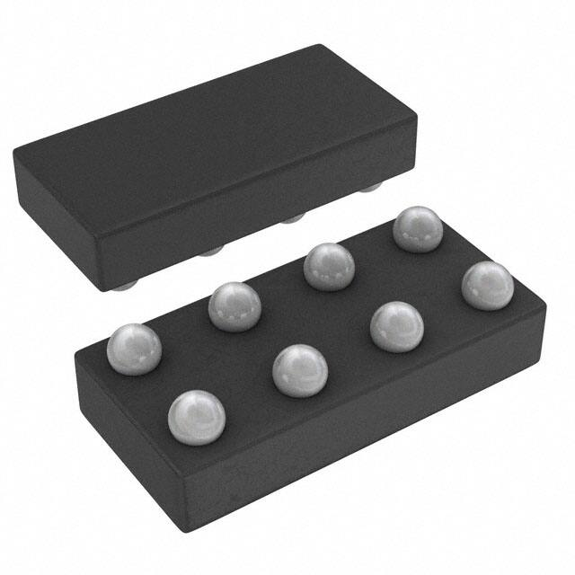


 工商网监
湘ICP备2023018690号
工商网监
湘ICP备2023018690号
