OBSOLETE
LMX2306, LMX2316, LMX2326
www.ti.com
SNAS016G – MAY 2000 – REVISED APRIL 2013
PLLatinum™ Low Power Frequency Synthesizer for RF Personal Communications
LMX2306 550 MHz, LMX2316 1.2 GHz, LMX2326 2.8 GHz
Check for Samples: LMX2306, LMX2316, LMX2326
FEATURES
DESCRIPTION
•
•
•
•
The LMX2306/16/26 are monolithic, integrated
frequency synthesizers with prescalers that are
designed to be used to generate a very stable low
noise signal for controlling the local oscillator of an
RF transceiver. They are fabricated using TI's ABiC V
silicon BiCMOS 0.5μ process.
1
2
•
•
•
•
•
2.3V to 5.5V Operation
Ultra Low Current Consumption
2.5V VCC JEDEC Standard Compatible
Programmable or Logical Power Down Mode:
– ICC = 1 μA Typical at 3V
Dual Modulus Prescaler:
– LMX2306: 8/9
– LMX2316/26: 32/33
Selectable Charge Pump Tri-state Mode
Selectable FastLock Mode with Timeout
Counter
MICROWIRE Interface
Digital Lock Detect
APPLICATIONS
•
•
•
•
•
Portable Wireless Communications (PCS/PCN,
Cordless)
Wireless Local Area Networks (WLANs)
Cable TV Tuners (CATV)
Pagers
Other Wireless Communication Systems
The LMX2306 contains a 8/9 dual modulus prescaler
while the LMX2316 and the LMX2326 have a 32/33
dual modulus prescaler. The LMX2306/16/26 employ
a digital phase locked loop technique. When
combined with a high quality reference oscillator and
loop filter, the LMX2306/16/26 provide the feedback
tuning voltage for a voltage controlled oscillator to
generate a low phase noise local oscillator signal.
Serial data is transferred into the LMX2306/16/26 via
a three wire interface (Data, Enable, Clock). Supply
voltage can range from 2.3V to 5.5V. The
LMX2306/16/26
feature
ultra
low
current
consumption; LMX2306 - 1.7 mA at 3V, LMX2316 2.5 mA at 3V, and LMX2326 - 4.7 mA at 3V.
The LMX2306/16/26 synthesizers are available in a
16-pin TSSOP surface mount plastic package.
Functional Block Diagram
1
2
Please be aware that an important notice concerning availability, standard warranty, and use in critical applications of
Texas Instruments semiconductor products and disclaimers thereto appears at the end of this data sheet.
PLLatinum is a trademark of Texas Instruments.
PRODUCTION DATA information is current as of publication date.
Products conform to specifications per the terms of the Texas
Instruments standard warranty. Production processing does not
necessarily include testing of all parameters.
Copyright © 2000–2013, Texas Instruments Incorporated
�OBSOLETE
LMX2306, LMX2316, LMX2326
SNAS016G – MAY 2000 – REVISED APRIL 2013
www.ti.com
Connection Diagrams
LMX2306/16/26
LMX2306/16/26
Figure 1. 16-Lead (0.173” Wide) Thin Shrink Small
Outline Pkg - TSSOP
See Package Number PW
Figure 2. 16-pin Chip Scale Package
PLGA
See Package Number NPG
Pin Descriptions
16-Pin 16-Pin
TSSOP PLGA
2
Pin
Name
I/
O
Description
1
15
FLo
O FastLock Output. For connection of parallel resistor to the loop filter. (See FastLock Modes description.)
2
16
CPo
O Charge Pump Output. For connection to a loop filter for driving the input of an external VCO.
3
1
GND
4
2
GND
5
3
fIN
I
RF Prescaler Complementary Input. A bypass capacitor should be placed as close as possible to this pin
and be connected directly to the ground plane. The complementary input can be left unbypassed, with
some degradation in RF sensitivity.
6
4
fIN
I
RF Prescaler Input. Small signal input from the VCO.
7
5
VCC1
8
6
OSCIN
9
7
GND
10
8
CE
I
Chip Enable. A LOW on CE powers down the device and will tri-state the charge pump output. Taking CE
HIGH will power up the device depending on the status of the power down bit F2. (See Powerdown
Operation and DEVICE PROGRAMMING AFTER FIRST APPLYING Vcc.)
11
9
Clock
I
High Impedance CMOS Clock Input. Data for the various counters is clocked in on the rising edge into
the 21-bit shift register.
12
10
Data
I
Binary Serial Data Input. Data entered MSB first. The last two bits are the control bits. High impedance
CMOS input.
13
11
LE
I
Load Enable CMOS Input. When LE goes HIGH, data stored in the shift registers is loaded into one of the
3 appropriate latches (control bit dependent).
14
12
Fo/LD
15
13
VCC2
16
14
VP
Charge Pump Ground.
Analog Ground.
Analog Power Supply Voltage Input. Input may range from 2.3V to 5.5V. Bypass capacitors should be
placed as close as possible to this pin and be connected directly to the ground plane. VCC1 must equal
VCC2.
I
Oscillator Input. This input is a CMOS input with a threshold of approximately VCC/2 and an equivalent
100k input resistance. The oscillator input is driven from a reference oscillator.
Digital Ground.
O Multiplexed Output of the RF Programmable or Reference Dividers and Lock Detect. CMOS output. (See
Table 4.)
Digital Power Supply Voltage Input. Input may range from 2.3V to 5.5V. Bypass capacitors should be
placed as close as possible to this pin and be connected directly to the ground plane. VCC1 must equal
VCC2.
Power Supply for Charge Pump. Must be ≥ VCC.
Submit Documentation Feedback
Copyright © 2000–2013, Texas Instruments Incorporated
Product Folder Links: LMX2306 LMX2316 LMX2326
�OBSOLETE
LMX2306, LMX2316, LMX2326
www.ti.com
SNAS016G – MAY 2000 – REVISED APRIL 2013
These devices have limited built-in ESD protection. The leads should be shorted together or the device placed in conductive foam
during storage or handling to prevent electrostatic damage to the MOS gates.
Absolute Maximum Ratings (1) (2)
Power Supply Voltage
VCC1
−0.3V to +6.5V
VCC2
−0.3V to +6.5V
Vp
−0.3V to +6.5V
−0.3V to VCC + 0.3V
Voltage on Any Pin with GND = 0V (VI)
−65°C to +150°C
Storage Temperature Range (TS)
Lead Temperature (TL)
(1)
(2)
(solder, 4 sec.)
+260°C
Absolute Maximum Ratings indicate limits beyond which damage to the device may occur. Recommended operating conditions indicate
conditions for which the device is intended to be functional, but do not ensured specific performance limits. For ensured specifications
and test conditions, see the Electrical Characteristics. The ensured specifications apply only for the test conditions listed.
This device is a high performance RF integrated circuit with an ESD rating < 2 kV and is ESD sensitive. Handling and assembly of this
device should only be done at ESD protected work stations.
Recommended Operating Conditions
Power Supply Voltage
Min
Max
Units
VCC1
2.3
5.5
V
VCC2
VCC1
VCC1
V
Vp
VCC
5.5
V
−40
+85
°C
Operating Temperature (TA)
Copyright © 2000–2013, Texas Instruments Incorporated
Product Folder Links: LMX2306 LMX2316 LMX2326
Submit Documentation Feedback
3
�OBSOLETE
LMX2306, LMX2316, LMX2326
SNAS016G – MAY 2000 – REVISED APRIL 2013
www.ti.com
Electrical Characteristics
VCC = 3.0V, Vp = 3.0V; −40°C < TA < 85°C except as specified
Symbol
ICC
Parameter
Power Supply Current
ICC-PWDN
Powerdown Current
fIN
RF Input Operating Frequency
Values
Conditions
Min
Typ
Max
Units
LMX2306
VCC = 2.3V to 5.5 V
1.7
3.5
mA
LMX2316
VCC = 2.3V to 5.5V
2.5
5.0
mA
LMX2326
VCC = 2.3V to 5.5V
4.7
7.0
mA
VCC = 3.0V
μA
1
LMX2306
VCC = 2.3V to 5.5V
25
550
MHz
LMX2316
VCC = 2.3V to 5.5V
0.1
1.2
GHz
LMX2326
VCC = 2.3V to 5.5V
0.1
2.1
GHz
VCC = 3.0V to 5.5V
0.1
2.8
GHz
VCC = 2.3V to 5.5V
5
40
MHz
VCC = 2.7V to 5.5V
5
100
MHz
10
MHz
fosc
Maximum Oscillator Frequency
fφ
Maximum Phase Detector Frequency
PfIN
RF Input Sensitivity
VCC = 2.3V to
很抱歉,暂时无法提供与“LMX2326SLBX/NOPB”相匹配的价格&库存,您可以联系我们找货
免费人工找货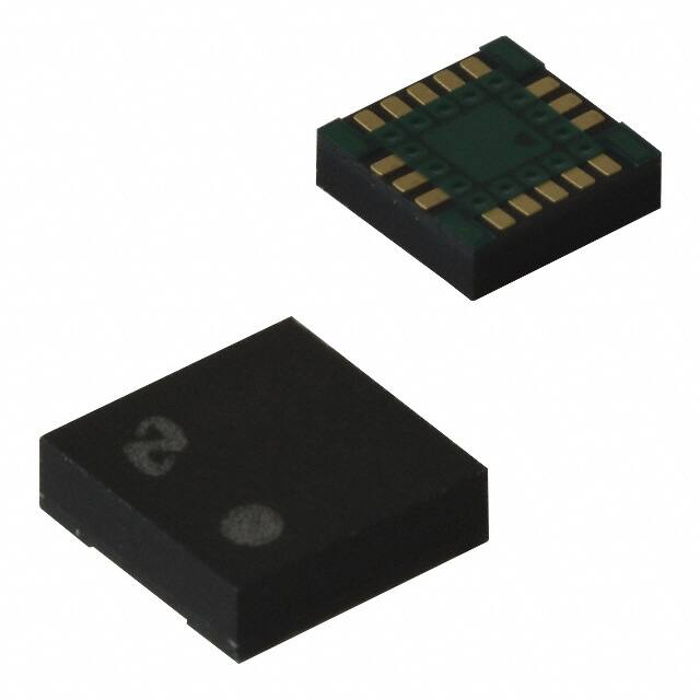


 工商网监
湘ICP备2023018690号
工商网监
湘ICP备2023018690号
