��������
�
SLUS610 − JULY 2004
��
��� ���� ���� ��������� ���
����
�� ��������� �����
FEATURES
D Wide Input Supply Range: −20 V to −80 V
D Transient Rating to −100 V
D Insertion/Removal Detection Delay
D Extended Debounce Delay
D Programmable Current Limit
D Programmable Current Slew Rate
D Programmable UV/OV Thresholds/Hysteresis
D Open-Drain Power Good (PG) Output
D Fault Timer to Eliminate Nuisance Trips
D Open-Drain Fault Output (FAULT)
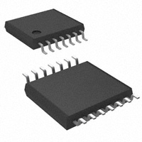
D 14-Pin TSSOP package
DESCRIPTION
The TPS2393A integrated circuit is a hot swap
power manager optimized for use in nominal
−48-V systems. It operates with supply voltage
ranges from −20-V to −80-V, and is rated to
withstand spikes to −100 V. In conjunction with an
external N-channel FET and sense resistor, it can
be used to enable live insertion of plug-in cards
and modules in powered systems. It provides load
current slew rate control and peak magnitude
limiting. Undervoltage and overvoltage shutdown
thresholds are easily programmed via a
three-resistor divider network. In addition, two
active-low, debounced inputs provide plug-in
insertion and removal detection. The associated
debounce delay applies to both actions. A power
good (PG) output enables downstream
converters. The TPS2393A also provides the
basic hot swap functions of electrical isolation of
faulty cards, filtered protection against nuisance
overcurrent trips, and single-line fault reporting.
APPLICATIONS
D −48-V Distributed Power Systems
D Central Office Switching
D Wireless Base Station
The TPS2393A periodically retries the load in the
event of a fault.
R7
56.2 k�� 1%
R1
200 k�� 1%
GND
DC/DC
CONVERTER
R2
4.99 k�� 1%
VIN+
D2
5.6 V
C2
0.047 �F
−48V
F1
VOUT+
COUT
EN
TPS2393A
R5
100 k�
C2
1500 pF
C4
100 �F
100 V
R6
10 k�
R3
3.92 k�
1%
VOUT+
VDD
1
UVLO
2
INSA DRAINSNS 13
3
INSB
4
FAULT
5
EN
6
FLTTIME ISENS 9
7
IRAMP
C2, 3900 pF
OVLO 14
VIN−
D1
BAS19
VOUT−
VOUT−
PG 12
RTN 11
GATE 10
−VIN 8
Q1
IRF530
R4
20 m�
1/4, 1%
VUV
= 32.8 V
VUV
= 30.8 V
VOV
= 72.6 V
R8, 56.2 k�� 1%
UDG−04073
Please be aware that an important notice concerning availability, standard warranty, and use in critical applications of
Texas Instruments semiconductor products and disclaimers thereto appears at the end of this data sheet.
���������� ���� �����!"#��� �$ %&��'�# "$ �� (&)*�%"#��� +"#',
���+&%#$ %�����! #� $('%���%"#���$ ('� #-' #'�!$ �� �'."$ ��$#�&!'�#$
$#"�+"�+ /"��"�#0, ���+&%#��� (��%'$$��1 +�'$ ��# �'%'$$"��*0 ��%*&+'
#'$#��1 �� "** ("�"!'#'�$,
Copyright 2004, Texas Instruments Incorporated
www.ti.com
1
���������
�
SLUS610 − JULY 2004
These devices have limited built-in ESD protection. The leads should be shorted together or the device placed in conductive foam
during storage or handling to prevent electrostatic damage to the MOS gates.
ORDERING INFORMATION
TA
−40°C to 85°C
FAULT OPERATION
PACKAGE
TSSOP (PW)(NO TAG)
PERIODIC RETRY
PART NUMBER
TPS2393APW
The PW package is also available taped and reeled. Add an R suffix to the device type (i.e., TPS2393APWR) for quantities of 2,500 per reel.
ABSOLUTE MAXIMUM RATINGS
over operating free-air temperature range unless otherwise noted(1)
TPS2393A
UVLO, INSA, INSB, FLTTIME, IRAMP, OVLO,
DRAINSNS, GATE, ISENS(2)
Input voltage range, VI
UNIT
−0.3 to 15
RTN(2)
EN(2)(3)
V
−0.3 to 100
FAULT(2)(4)
PG(2)(4)
Output voltage range, VO
FAULT
Continuous output current
10
PG
mA
Operating junction temperature range, TJ
−55 to 125
Storage temperature, Tstg
−65 to 150
Lead temperature 1,6 mm (1/16 inch) from case for 10 seconds
°C
C
260
Stresses beyond those listed under “absolute maximum ratings” may cause permanent damage to the device. These are stress ratings only, and
functional operation of the device at these or any other conditions beyond those indicated under “recommended operating conditions” is not
implied. Exposure to absolute-maximum-rated conditions for extended periods may affect device reliability.
All voltages are with respect to −VIN (unless otherwise noted).
With 100-kΩ minimum input series resistance.
With 10-kΩ minimum series resistance.
RECOMMENDED OPERATING CONDITIONS
MIN
NOM
MAX
UNIT
Input supply voltage, −VIN to RTN
−80
−20
V
Operating junction temperature, TJ
−40
85
°C
DISSIPATION RATINGS
PACKAGE
TA < 25°C
POWER RATING
DERATING FACTOR
ABOVE TA = 25°C
TA = 85°C
POWER RATING
TSSOP−14
750 mW
7.5 mW/°C
300 mW
PW PACKAGE
(TOP VIEW)
UVLO
INSA
INSB
FAULT
EN
FLTTIME
IRAMP
2
1
2
3
4
5
6
7
14
13
12
11
10
9
8
www.ti.com
OVLO
DRAINSNS
PG
RTN
GATE
ISENS
−VIN
���������
�
SLUS610 − JULY 2004
ELECTRICAL CHARACTERISTICS
VI(−VIN) = −48 V with respect to RTN, VI(EN) = 2.8 V, VI(INSA) = 0 V, VI(INSB) = 0 V, VI(UVLO) = 2.5 V, VI(OVLO) = 0 V, VI(ISENS)
unloaded, TA = −40°C to 85°C (unless otherwise noted)(1)(2)
PARAMETER
TEST CONDITIONS
MIN
all outputs
TYP
MAX
1050
1500
1350
1700
−16
−13
UNIT
INPUT SUPPLY
ICC1
ICC2
VUVLO_L
VHYS
Supply current, RTN
VI(RTN) = 48 V
VI(RTN) = 80 V
Internal UVLO threshold, VIN rising
To GATE pull-up
−19
Internal UVLO hysteresis
200
A
µA
V
mV
ENABLE INPUT (EN)
VTH
ISRC_EN
Threshold voltage, VIN rising
To GATE pull-up
EN pin switched pull-up current
1.3
1.4
1.5
V
−12
−10
−8
µA
UNDERVOLTAGE/OVERVOLTAGE COMPARATORS
VTH_UV
ISRC_UV
Threshold voltage, VIN rising, UVLO
To GATE pull-up
1.36
1.40
1.44
V
UVLO pin switched pull-up current
−10.0
−8.3
µA
UVLO low-level input current
VI(UVLO) = 2.5 V
VI(UVLO) = 1 V
−11.7
IIL
VTH_OV
1
µA
Threshold voltage, VIN rising, OVLO
To GATE pull-up
1.36
1.40
1.44
V
ISRC_OV
IIL
OLVO pin switched pull-up current
VI(OVLO) = 2.5 V
VI(OVLO) = 1 V
−11.7
−10.0
−8.3
µA
1
µA
OVLO low-level input current
−1
−1
INSERTION DETECTION
VTH
ISRC_INS
x
Threshold voltage, VIN rising, INSA, INSB
To GATE pull-down
1.0
1.4
1.8
V
INSA, INSB pin pull-up current
VI(INSA) = 0 V, VI(INSB) = 0 V
−14
−11
−8
µA
tD_INSF
tD_INSR
Insertion delay time, VIN falling, INSA, INSB
To GATE pull-up
4.25
6.20
8.25
ms
Extraction delay time, VIN rising, INSA, INSB
LINEAR CURRENT AMPLIFIER (LCA)
To GATE pull-down
4.25
6.20
8.25
ms
VOH
High-level output voltage, GATE
11
14
17
ISINK
Output sink current, linear mode
VI(ISENS) = 0 V, IO(GATE) = −10 µA
VI(ISENS) = 80 mV, VO(GATE) = 5 V
VO(FLTTIME) = 2 V
5
10
IFAULT
Output sink current, fault shutdown
VI(ISENS) = 80 mV, VO(GATE) = 5 V
VO(FLTTIME) > 4 V
50
II
VREF_K
Input current, ISENS
0 V < VI(ISENS) < 0.2 V
−1
Reference clamp voltage
VO(IRAMP) = OPEN
VO(IRAMP) = 2 V
33
VO(IRAMP) = 0.25 V
VO(IRAMP) = 1 V
−850
−600
−400
−11
−10
−9
−11
−10
−9
VIO
Input offset voltage
RAMP GENERATOR
ISRC1
IRAMP source current, reduced rate turn-on
ISRC2
IRAMP source current, normal rate
VOL
AV
Low-level output voltage, IRAMP
VO(IRAMP) = 3 V
VI(EN) = 0 V
Voltage gain, relative to ISENS
V
mA
100
1
40
−7
µA
47
7
2
mV
nA
A
µA
mV
9.5
10.0
10.5
mV/V
80
100
120
mV
2
4
7
µs
OVERLOAD COMPARATOR
VTH_OL
tDLY
(1)
(2)
Current overload threshold, ISENS
Glitch filter delay time
VI(ISENS) = 200 mV
All voltages are with respect to the −VIN terminal, unless otherwise stated.
Currents are positive into and negative out of the specified terminals.
www.ti.com
3
���������
�
SLUS610 − JULY 2004
ELECTRICAL CHARACTERISTICS (continued)
VI(−VIN) = −48 V with respect to RTN, VI(EN) = 2.8 V, VI(INSA) = 0 V, VI(INSB) = 0 V, VI(UVLO) = 2.5 V, VI(OVLO) = 0 V, VI(ISENS)
unloaded, TA = −40°C to 85°C (unless otherwise noted)
all outputs
PARAMETER
TEST CONDITIONS
MIN
TYP
MAX
UNIT
VOL
ICHG
Low-level output voltage, FLTTIME
VI(EN) = 0 V
VI(ISENS) = 80 mV, VO(FLTTIME) = 2 V
5
mV
−55
−50
−45
µA
VFLT
IDSG
Fault threshold voltage
3.75
4.00
4.25
V
0.38
0.61
µA
D
Output duty cycle
1.0%
1.5%
FAULT TIMER
Charging current, current limit mode
Discharge current, retry mode
TPS2393
TPS2393
IRST
Discharge current, timer reset mode
POWERGOOD SENSING
VTH
ISRC
DRAINSNS threshold voltage
IOH
High-level output leakage current, PG output
DRAINSNS pull-up current
RDS(on) Driver on-resistance, PG output
VI(ISENS) = 80 mV, VO(FLTTIME) = 2 V
VI(ISENS) = 80 mV
VO(FLTTIME) = 2 V, VI(ISENS) = 0 V
VI(DRAINSNS) = 0 V
VI(EN) = 0 V, VO(PG) = 65 V
VI(ISENS) = 0 V, VI(DRAINSNS) = 0 V
IO(PG) = 1 mA
1
mA
1.20
1.35
1.50
−14
−11
−8
10
50
V
A
µA
80
Ω
10
µA
80
Ω
FAULT OUTPUT
IOH
High-level output leakage current, FAULT
RDS(on) Driver on-resistance, FAULT
(1)
(2)
VI(EN) = 0 V, VO(FAULT) = 65 V
VI(ISENS) = 80 V, VO(FLTTIME) = 5 V
IO(FAULT) = 1 mA
All voltages are with respect to the −VIN terminal, unless otherwise stated.
Currents are positive into and negative out of the specified terminals.
TERMINAL FUNCTIONS
TERMINAL
I/O
DESCRIPTION
NAME
NO.
DRAINSNS
13
I
Sense input for monitoring the load voltage status
EN
5
I
Enable input to turn on/off power to the load
FAULT
4
O
Open-drain, active-low indication of a load fault condition
FLTTIME
6
I/O
Connection for user-programming of the fault timeout period
GATE
10
O
Gate drive for external N−channel FET
INSA
2
I
Insertion detection input pin A
INSB
3
I
Insertion detection input pin B
IRAMP
7
I/O
ISENS
9
I
Current sense input
OVLO
14
I
Voltage sense input for supply overvoltage lockout (OVLO) protection
PG
12
O
Open-drain, active-low indication of load power-good condition
RTN
11
I
Positive supply input
UVLO
1
I
Voltage sense input for supply undervoltage lockout (UVLO) protection
−VIN
8
I
Negative supply input and reference pin
4
Programming input for setting the inrush current slew rate
www.ti.com
50
���������
�
SLUS610 − JULY 2004
PIN ASSIGNMENTS
DRAINSNS: Sense input for monitoring the load voltage status. The DRAINSNS pin determines the load status
by sensing the voltage level on the external pass FET drain. DRAINSNS must be pulled low with repect to −VIN
(less than 1.35 V typically) to declare a power good condition. This corresponds to a low VDS across the FET,
indicating that the load voltage has successfully ramped up to the DC input level. DRAINSNS must be connected
to the FET drain through a small-signal blocking diode as shown in the typical application diagram. An internal
pull-up maintains a high logic level at the pin until overridden by a fully-enhanced external FET.
EN: Enable input to turn on/off power to the load. The EN pin is referenced to the −VIN potential of the circuit.
When this input is pulled high (above the nominal 1.4-V threshold), and all other input qualifications are met
(supply above device undervoltage lockout (UVLO), UVLO pin high and OVLO pin low, INSx pins pulled low)
the device enables the GATE output, and begins the ramp of current to the load. When this input is low, the linear
current amplifier (LCA) is disabled, and a large pull-down device is applied to the FET gate, disabling power
to the load.
FAULT: Open-drain, active-low indication of a load fault condition. When the device EN is deasserted, or when
enabled and the load current is less than the programmed limit, this output is high impedance. If the device
remains in current regulation mode at the expiration of the fault timer, the fault is latched, the load is turned off,
and the FAULT pin is pulled low (to −VIN). The TPS2393A retries the load at approximately a 1% duty cycle.
FLTTIME: Connection for user-programming of the fault timeout period. An external capacitor connected from
FLTTIME to −VIN establishes the timeout period to declare a fault condtion. This timeout protects against
indefinite current sourcing into a faulted load, and also provides a filter against nuisance trips from momentary
current spikes or surges. The TPS2393A defines a fault condition as voltage at the ISENS pin at or greater than
the 40-mV fault threshold. When a fault condition exists, the timer is active. The device manages fault timing
by charging the external capacitor to the 4-V fault threshold, then discharging it at approximately 1% the charge
rate to establish the duty cycle for retrying the load. Whenever the internal fault latch is set (timer expired), the
pass FET is rapidly turned off, and the FAULT output is asserted.
GATE: Gate drive for external N−channel FET. When enabled, and the input supply is above the UVLO
threshold, the gate drive is enabled and the device begins charging an external capacitor connected to the
IRAMP pin. This pin voltage is used to develop the reference voltage at the non-inverting input of the internal
LCA. The inverting input is connected to the current sense node, ISENS. The LCA acts to slew the pass FET
gate to force the ISENS voltage to track the reference. The reference is internally clamped at 40 mV, so the
maximum current that can be sourced to the load is determined by the sense resistor value as IMAX ≤ 40
mV/RSENSE. Once the load voltage has ramped up to the input dc potential, and current demand drops off, the
LCA drives the GATE output to about 14 V to fully enhance the pass FET, completing the low-impedance supply
return path for the load.
INSA: Insertion detection input pin A. The INSA and INSB inputs work together to provide an insertion detection
function for TPS2393A applications. In order to turn on the FET gate drive (the GATE output), both INSA and
INSB must be pulled below the detection threshold, approximatey 1.4 V. Implementations using this feature
provide a mechanism for resistively pulling these pins to −VIN potential (device ground), through the backplane
wiring. When used with slot connector pin staging this feature can keep the plug-in powered off during contact
bounce periods of the power pins. An on-chip pull-up is provided at each INSx pin; no additional pull-up is
needed to hold the pins high during the insertion and extraction processes. The insertion inputs are debounced
with a nominal 6.2-ms filter.
INSB: Insertion detection input pin B. See INSA description.
www.ti.com
5
���������
�
SLUS610 − JULY 2004
PIN ASSIGNMENTS
IRAMP: Programming input for setting the inrush current slew rate. An external capacitor connected between
this pin and −VIN establishes the load current slew rate whenever power to the load is enabled. The device
charges the external capacitor to establish the reference input to the LCA. The closed-loop control of the LCA
and pass FET acts to maintain the current sense voltage at ISENS at the reference potential. Since the sense
voltage is developed as the drop across a resistor, the load current slew rate is set by the voltage ramp rate at
the IRAMP pin. When the output is disabled for any reason (e.g., EN deassertion, voltage or current fault, etc.),
the capacitor is discharged and held low to initialize it for the next turn-on event.
ISENS: Current sense input. An external low-value resistor connected between this pin and −VIN is used to feed
back current magnitude information to the TPS2393A. There are two internal device thresholds associated with
the voltage at the ISENS pin. During ramp-up of the load’s input capacitance, or during other periods of
excessive demand, the HSPM acts to limit this voltage to 40 mV. Whenever the LCA is in current regulation
mode, the capacitor at FLTTIME is charged to activate the timer. If, when the LCA is driving to its supply rail,
a fast-acting fault such as a short-circuit, causes the ISENS voltage to exceed 100 mV (the overload threshold),
the GATE pin is pulled low rapidly, bypassing the fault timer. Overload faults are not immediately latched. Once
the current drops below the 100-mV threshold due to the GATE pull-down, control is quickly returned to the LCA
to turn the FET back on in current limit mode and test the persistance of the fault.
OVLO: Voltage sense input for supply overvoltage lockout (OVLO) protection. Overvoltage protection can be
achieved by applying a divided down sample of the input supply voltage to this pin. In order to turn on gate drive
to the external FET, the OVLO pin must be below the 1.4-V typical threshold, while all other input qualifications
are met. If the OVLO pin is raised above this threshold, as with increasing supply voltage, the GATE output is
pulled low, interrupting the supply to the load. An internal 10-µA pull-up is switched to this pin when the threshold
is exceeded, providing a mechanism for setting the amount of OVLO hysteresis along with the trip threshold.
PG: Open-drain, active-low indication of load power good condition. The TPS2393A device defines power good
as the voltage at the DRAINSNS pin below the power good threshold, and the voltage at the IRAMP pin being
above 5 V. This assures that full programmed sourcing current is available to the load prior to declaring power
good, even with very slow current ramp rates. The additional protection prevents potential discharging of the
module bulk capacitance during load turn-on.
RTN: Positive supply input for the TPS2393A. For negative voltage systems, the supply pin connects directly
to the return node of the input power bus. Internal regulators step down the input voltage to generate the various
supply levels used by the TPS2393A.
UVLO: Voltage sense input for supply uvervoltage lockout (UVLO) protection. Undervoltage protection can be
achieved by applying a divided down sample of the input supply voltage to this pin. In order to turn on the gate
drive to the external FET, the UVLO pin must be above the 1.4-V typical threshold, while all other input
qualifications are met. If the UVLO pin drops below this threshold, as with decreasing supply voltage, the GATE
output is pulled low, interrupting the supply to the load. An internal 10-µA pull−up is switched to this pin when
the threshold is exceeded, providing a mechanism for setting the amount of UVLO hysteresis along with the
trip threshold.
For proper operation, a minimum 1500-pF capacitor, connected between the UVLO and −VIN pins, is required.
−VIN: Negative supply input and reference pin for the TPS2393A. This pin connects directly to the input supply
negative rail. The input and output pins and all internal circuitry are referenced to this pin, so it is essentially the
GND or VSS pin of the device.
6
www.ti.com
���������
�
SLUS610 − JULY 2004
TYPICAL CHARACTERISTICS
EN (5 V/div)
EN (5 V/div)
VDRAIN
(20 V/div)
VDRAIN
(50 V/div)
CONTACT
BOUNCE
CONTACT
BOUNCE
ILOAD
(500 mA/div)
CIRAMP = 3900
pF
CFLT = 0.1 µF
CLOAD = 50 µF
ILOAD
(500 mA/div)
CLOAD = 100 µF
t − Time − 2.5 ms / div
t − Time − 1 ms / div
Figure 1. Live Insertion Event − VIN = −48 V
VDRAIN (50 V/div)
Figure 2. Live Insertion Event − VIN = −70 V
CLOAD = 50
µF
VUVLO_L
FLTTIME (2 V/div)
RTN (5 V/div)
ILOAD (1 A/div)
FAULT (20 V/div)
CIRAMP = 3900
pF
CFLT = 0.047 µF
GATE (5 V/div)
t − Time − 5 ms / div
t − Time − 1 ms / div
Figure 3. Turn-On Into Shorted Load
Figure 4. UVLO Protection, Supply Rising
www.ti.com
7
���������
�
SLUS610 − JULY 2004
TYPICAL CHARACTERISTICS
VUVLO_H
INSB
(5 V/div.)
RTN (5 V/div)
RAMP
(2 V/div.)
Extraction
Delay
Insertion
Delay
GATE (5 V/div)
CLOAD = 50 µF
RLOAD = 1 kΩ
VDRAIN(20V/div.)
t − Time − 5 ms / div
t − Time − 1 ms / div
Figure 6. Insertion/Extraction Detection
Figure 5. UVLO Protection, Supply Falling
FAULT (50 V/div)
IRAMP (2 V/div)
CIRAMP
=
3900 pF
PG (50 V/div)
CIRAMP = .022 µF
CIRAMP = .056 µF
CFLT = 0.33 µF
CLOAD = 600 µF
CIRAMP = 3900 pF
CFLT = 0.047 µF
CLOAD = 100 µF
RLOAD = 12.5 Ω
FLTTIME (2 V/div)
VDRAIN (50 V/div)
ILOAD
ILOAD (1 A/div)
(500 mA/div)
t − Time − 50 ms / div
t − Time − 10 ms / div
Figure 7. Load Current Ramp Profiles
8
Figure 8. Fault Retry Operation
www.ti.com
���������
�
SLUS610 − JULY 2004
TYPICAL CHARACTERISTICS
FAULT (50 V/div)
FAULT (50 V/div)
CIRAMP = 3900 pF
CFLT = 0.047 µF
CLOAD = 100 µF
PG (50 V/div)
CIRAMP = 3900 pF
CFLT = 0.047 µF
CLOAD = 100 µF
PG (50 V/div)
FLTTIME (2 V/div)
FLTTIME (2 V/div)
VDRAIN
(50 V/div)
VDRAIN (50 V/div)
ILOAD
(1 A/div)
ILOAD (1 A/div)
t − Time − 50 ms / div
t − Time − 1 ms / div
Figure 9. Fault Recovery (Large Scale View)
Figure 10. Fault Recovery − Expanded View
CIRAMP = 3900 pF
CLOAD = 220 µF
IRAMP (2 V/div)
CIRAMP = 6800 pF
CLOAD = 50 µF
VTH_PG
IRAMP (2 V/div)
VDRAIN (20 V/div)
VDRAIN (20 V/div)
PG (50 V/div)
PG (50 V/div)
t − Time − 1 ms / div
t − Time − 1 ms / div
Figure 11. PG Output Timing, Voltage Qualified
Figure 12. PG Output Timing, Current Qualified
www.ti.com
9
���������
�
SLUS610 − JULY 2004
TYPICAL CHARACTERISTICS
SUPPLY CURRENT
vs
AMBIENT TEMPERATURE
1500
16
VOH − Output Voltage − V
ICC − Supply Current − µA
900
VRTN = 48
V
600
VRTN = 36
V
300
0
−40
−15
VRTN = 20
V
35
10
VI(ISENS) = 0 V
IO(GATE) = −10 µA
15
VRTN = 80 V
1200
GATE HIGH-LEVEL OUTPUT VOLTAGE
vs
AMBIENT TEMPERATURE
14
VRTN = 36
V
13
12
VRTN = 20
V
11
60
10
−40
85
TA − Ambient Temperature − °C
−15
10
35
60
TA − Ambient Temperature − °C
Figure 13.
−9.0
ISRC2 − IRAMP Output Current − µA
ISRC1 − IRAMP Output Current − nA
IRAMP OUTPUT CURRENT
vs
AMBIENT TEMPERATURE, NORMAL RATE
VO(IRAMP) = 0.25 V
−520
VRTN = 48
V
VRTN = 20
V
−540
−560
VRTN = 80
V
−580
−600
−620
−40
−15
10
35
60
85
Average for VO(IRAMP) = 1 V, 3 V
VRTN = 20 V to 80 V
−9.4
−9.8
−10.2
−10.6
−11.0
−40
−15
10
35
TA − Ambient Temperature − °C
TA − Ambient Temperature − °C
Figure 16.
Figure 15.
10
85
Figure 14.
IRAMP OUTPUT CURRENT
vs
AMBIENT TEMPERATURE, REDUCED RATE
−500
VRTN = 80
V
VRTN = 48
V
www.ti.com
60
85
���������
�
SLUS610 − JULY 2004
TYPICAL CHARACTERISTICS
TIMER CHARGING CURRENT
vs
AMBIENT TEMPERATURE
−47
440
VI(ISENS) = 80 mV
VO(FLTTIME) =2V
VI(ISENS) = 80 mV
VO(FLTTIME) = 2 V
VI(RTN) = 20 V to 80 V
−48
400
VRTN = 20 V
IDSG − Charging Current − nA
ICHG − Charging Current − µA
TIMER DISCHARGE CURRENT
vs
AMBIENT TEMPERATURE
−49
−50
−51
VRTN = 36 V
VRTN = 48 V
VRTN = 80 V
−52
−53
−40
−15
10
35
60
360
320
280
240
−40
85
TA − Ambient Temperature − °C
Figure 17.
VOLTAGE COMPARATOR THRESHOLD
vs
AMBIENT TEMPERATURE
1.44
VI(RTN) = 48 V
VTH − Voltage Comparator Threshold − V
VFLT − Fault Latch Threshold Voltage − V
85
Figure 18.
FAULT LATCH THRESHOLD
vs
AMBIENT TEMPERATURE
4.25
−15
10
35
60
TA − Ambient Temperature − °C
4.15
4.05
3.95
3.85
3.75
−40
−15
10
35
60
85
1.42
VI(RTN) = 20 V to 48 V
Undervoltage
Comparator
1.40
Overvoltage
Comparator
VI(RTN) = 80 V
1.38
1.36
−40
TA − Ambient Temperature − °C
−15
10
35
60
TA − Ambient Temperature − °C
85
Figure 20.
Figure 19.
www.ti.com
11
���������
�
SLUS610 − JULY 2004
TYPICAL CHARACTERISTICS
UVLO PIN PULL-UP CURRENT
vs
AMBIENT TEMPERATURE
ISRC_UV − Sourced Current − µA
−9.3
VI(UVLO) = 2.5 V
VI(RTN) = 20 V to 48
V
−9.5
−9.7
−9.9
−10.1
−10.3
−40
−15
10
35
60
TA − Ambient Temperature − °C
85
Figure 21.
DETAILED DESCRIPTION
When a plug-in module or printed circuit card is inserted into a live chassis slot, discharged supply bulk
capacitance on the board can draw huge transient currents from the system supplies. Without some form of
inrush limiting, these currents can reach peak magnitudes ranging over 100 A, particularly in high-voltage
systems. Such large transients can damage connector pins, PCB etch, and plug-in and supply components.
In addition, current spikes can cause voltage droops on the power distribution bus, causing other boards in the
system to reset.
The TPS2393A is a hot swap power manager that limits current peaks to preset levels, as well as controls the
slew rate (di/dt) at which charging current ramps to the programmed limit. This device uses an external
N-channel pass FET and sense element to provide closed-loop control of current sourced to the load. Input
undervoltage lockout (UVLO) and overvoltage lockout (OVLO) functions control automatic turn-on when the
input supply voltage is within the specified operational window, otherwise inhibiting card operation by turning
off the pass FET. In addition, load power can be controlled with a system logic command via the EN input,
allowing electrical isolation of faulty cards from the power bus. Two active-low inputs can be connected to
provide card insertion detection. An internal overload comparator provides circuit breaker protection against
short-circuits occurring during steady-state (post-turn-on) operation of the card. Load power status is
continuously monitored and reported via the PG (powergood) and FAULT outputs.
12
www.ti.com
���������
�
SLUS610 − JULY 2004
DETAILED DESCRIPTION
The TPS2393A operates directly from the input supply (nominal −48 VDC) rail. The −VIN pin connects to the
negative voltage rail, and the RTN pin connects to the supply return. Internal regulators convert input power to
the supply levels required by the device circuitry. An input UVLO circuit holds the GATE output low until the
supply voltage reaches a nominal 16-V level, regardless of the status of all other control inputs. A block of
comparators monitors input supply voltage and other output enable conditions. As shown in Figure 24, the
status of these five comparators is AND’d together in order to enable turning on power to the load. Two precision
comparators monitor the voltage levels at the UVLO and OVLO pins. Typically, these pins are driven with a
divided-down sample of the supply voltage to establish the UVLO and OVLO trip thresholds for the circuit. The
UVLO input must be above the internal 1.4-V reference, and the OVLO pin must remain below the reference
voltage to enable the load. Both of these inputs are provided with a small, 10-µA pull-up source, which is
switched to the input pin whenever the associated comparator is tripped. These current sources provide a
mechanism for user-programming of the amount of hysteresis for the UVLO and OVLO thresholds.
The same comparator circuit is also available at the EN pin, providing a third precision input. A switched pull-up
is also available at this pin for hysteresis programming. Alternatively, this input can be used as a logic enable
command, with a nominal 1.4-V logic threshold.
The INSA and INSB pins provide an optional insertion detection function to the hot swap circuit. Both these pins
must be pulled low, below 1.0 -V to enable a load start-up. Internal pull-ups at these inputs maintain a HI logic
level (about 6.5 V) at the device pins when floating. This eliminates the need for additional external components
to maintain the HI logic level during insertion and extraction events. An external mechanism for pulling these
inputs low, typically though backplane connections to the low-side rail, starts a timer to hold off power up during
contact bounce. Loss of either input assertion resets the timer. Once the inserted condition is latched with
expiration of the 6-ms timer, the timer is then used to filter the inputs against transient spikes due to supply noise
and glitches in the power distribution.
Once the device is enabled (internal EN_A signal asserted), the GATE output pull-down is turned off, and the
linear control amplifier (LCA) is enabled. A current source in the ramp generator block begins charging an
external capacitor connected between the IRAMP and −VIN pins. The resultant voltage ramp at the IRAMP pin
is scaled by a factor of 1/100, and applied to the non-inverting input of the LCA (the VLIM signal). Load current
magnitude information at the ISENS pin is applied to the inverting input. This sense voltage is developed by
connecting the current sense resistor between ISENS and −VIN. As the external FET begins to conduct, the
LCA slews its gate to force the ISENS voltage to track the internal reference (VLIM). Consequently, the load
current slew rate tracks the linear voltage ramp at the IRAMP pin, producing a linear di/dt of current to the load.
www.ti.com
13
���������
�
SLUS610 − JULY 2004
DETAILED DESCRIPTION
10 �A
RTN
11
10 �A
1.35V
13
DRAINSNS
12
PG
7
IRAMP
4
FAULT
6
FLTTIME
9
ISENS
10
GATE
+
+
INSA
2
10 �A
+
S
Q
R
Q
5V
+
INSB
FLT
3
10 �A
EN_A
H=CLOSED
UVLO
1
RAMP
GENERATOR
+
VLIM
FLT
10 �A
ON
L=CLOSED
EN
OVLO 14
FAULT
TIMER
+
OC
10 �A
EN
5
H=CLOSED
S
Q
R
R
Q
OL FT
OVERLOAD
OVERCURRENT
100 mV
OLC
+
+
VLIM
1.4V
−VIN
S
LCA
+
EN_A
8
UDG−02116
Figure 22. Block Diagram
Under normal load and input supply conditions, this controlled current charges the module’s input bulk
capacitance up to the input dc voltage level. At this point, the load demand drops off, and the voltage at ISENS
decreases. The LCA now drives the GATE output to its supply rail. The 14-V typical output level ensures
sufficient overdrive to fully enhance the external FET, while not exceeding the typical 20-V VGS rating of common
N-channel power MOSFETs.
14
www.ti.com
���������
�
SLUS610 − JULY 2004
DETAILED DESCRIPTION
Current fault response timing and retry duty cycle are accomplished by the fault timer block in conjunction with
an external capacitor connected between the FLTTIME and −VIN pins. Whenever the hot swap controller is in
current control mode, such as during inrush limiting at insertion, or in response to excessive demand during
operation of the plug-in, the LCA asserts the OVERCURRENT signal shown in Figure 24. This signal starts the
charging of the FLTTIME capacitor. If this capacitor charges to the pin’s 4-V trip threshold, the fault is latched.
A latched fault disables the LCA drive, and turns on a large pull-down device at the GATE output to rapidly turn
off the external FET. The fault condition is indicated by turning on the open-drain FAULT output driver. A latched
fault also causes discharge of the external capacitor at the IRAMP pin, in order to reset the hot swap circuit for
the next output enable event. Slow discharge of the timing capacitor at about 1/100th the charging rate initiates
fault retry operation at a 1% duty cycle. This enables periodic testing for persistance or removal of the fault
condition.
An internal overload comparator (OLC in Figure 24) also monitors the ISENS voltage against a nominal 100-mV
threshold. This comparator provides circuit breaker protection against sudden current fault conditions, such as
a load short-circuit. The OVERLOAD output of this comparator also drives the fault timer. In this case, the timer
circuit applies only a 4-µs deglitch filter to help reduce nuisance trips. However, if the overload condition exceeds
the filter length, the FET is momentarily snapped off, after which it is quickly turned back on in current ramp or
current limit mode. At this point, fault timing commences as above.
The PG pin is an open-drain, active-low indication of a load power good status. Load voltage sensing is provided
at the DRAINSNS pin. To assert PG, the device must not be in latched current fault status, the DRAINSNS pin
must be pulled below the 1.35-V nominal threshold, and the voltage at the IRAMP pin must be greater than
approximately 5 V. This last criteria ensures that maximum allowed sourcing current is available to the load
before declaring power good. Once all the conditions are met, the PG status is latched on-chip. This prevents
instances of momentary current-limit operation (e.g., due to load surges or voltage spikes on the input supply)
from propagating through to the PG output. However, if input conditions are not met, or if a persistent load fault
does result in fault timeout, the PG latch will be cleared.
Additional details of the ramp generator operation are shown in Figure 25. To enable the generator, the large
NMOS device shown in this circuit is turned off. This allows a small current source to charge the external
capacitor connected at the IRAMP pin. The voltage ramp on the capacitor actually has two discrete, linear
slopes. As shown in Figure 25, current is supplied from either of two sources. An internal comparator monitors
the IRAMP voltage level, and selects the appropriate charging rate. Initially at turn-on, when the pin voltage is
0 V, the 600-nA source is selected, to provide a slow turn-on (or reduced-rate) sourcing period. This slow turn-on
ensures that the LCA is pulled out of saturation, and is slewing to the voltage at its non-inverting input before
normal rate load charging is allowed. This scheme helps reduce or eliminate current steps at the external FET
on-threshold. Once the voltage at the IRAMP pin reaches approximately 0.5 V, the SLOW signal is deasserted,
and the 10-µA source is selected for the remainder of the ramp period.
The IRAMP pin voltage is divided down by a factor of 100, and applied to the non-inverting input of the LCA (see
Figure 24). Although the IRAMP capacitor is charged to about 6.5 V, the VLIM reference is clamped at 40 mV.
Therefore, current sourced to the load during turn-on is limited to a value given by IMAX ≤ 40 mV/RSENSE, where
RSENSE is the value of the external sense resistor. Therefore, both load current maximum slew rate and peak
magnitude are easily set with just two external components.
www.ti.com
15
���������
�
SLUS610 − JULY 2004
DETAILED DESCRIPTION
10 µA
600 nA
SLOW
+
0.5 V
IRAMP
VLIM
99R
R
EN_A
40mV
UDG−20117
Figure 23. Ramp Generator Block Details
Note that any condition which causes turn-off of the external FET (EN_A signal goes low) also causes a rapid
discharge of the IRAMP capacitor. In this manner, the soft-start function is automatically reset by the TPS2393A,
and ready for the next load enable event.
Fault timer operation is further detailed in Figure 26. As described earlier, the LCA OVERCURRENT output
drives the OC input signal shown in Figure 26. Overcurrent fault timing is actually inhibited during the reduced
rate (slow turn-on) portion of the IRAMP voltage waveform. However, once the device transitions to the normal
rate current ramp (VO(IRAMP) ≥ 0.5 V), the FLTTIME capacitor is charge by the 50-µA current source, generating
a second voltage ramp at the FLTTIME pin. This voltage is monitored by the two comparators shown in the fault
timer block. If this voltage reaches the nominal 4-V comparator threshold, the fault is latched, the GATE pin
pulled low rapidly, and the FAULT output asserted. Once a fault is latched, capacitor charging ceases (ON signal
deasserted) and the timing capacitor is discharged.
In response to a latched fault condition, the TPS2393A enters a fault retry mode, wherein it periodically retries
the load to test for continued existence of the fault. In this mode, the FLTTIME capacitor is discharged slowly
by a about a 0.4-µA constant-current sink. When the voltage at the FLTTIME pin decays below 0.5 V, the ON
signal once again enables the LCA and ramp generator circuits, and a normal turn-on current ramp ensues.
Again, during the load charging, the OC signal causes charging of the FLTTIME capacitor until the next delay
period elapses. The sequential charging and discharging of the FLTTIME capacitor results in a typical 1% retry
duty cycle. If the current-limit fault subsides (GATE pin drives to high-level output), the timing cap is rapidly
discharged (reset signal asserted), duty-cycle operation stops, and the fault latch is reset.
Note that because of the timing inhibit during the initial slow ramp period, the duty cycle in practice is slightly
greater than the nominal 1% value. However, sourced current during this period peaks at only about one-eighth
the maximum limit. The duty cycle of the normal ramp and constant-current periods will be about 1%.
16
www.ti.com
���������
�
SLUS610 − JULY 2004
DETAILED DESCRIPTION
OL
4 �s
50 �A
OC
4
4V
S
S
Q
R
Q
FAULT
+
FLTTIME
6
RETRY
0.4 �A
ON
+
0.5V
RESET
FAULT
LOGIC
R
EN
UDG−20118
Figure 24. Fault Timer Block Operation
The fault logic within the timer block automatically manages capacitor charge and discharge rates (RESET
signal), and the operational status of other device-internal circuits (ON signal). The FAULT output remains
asserted continuously during retry mode; it is only released if the fault condition clears.
The TPS2393A also features a fast-acting overload comparator which clamps large current transients from
catastrophic faults occurring once the pass FET is fully enhanced, such as short circuits. This function provides
a back-up protection to the LCA by producing a hard gate discharge action when the LCA is saturated and the
pass FET is fully enhanced. If sense voltage excursions above 100 mV are detected, this comparator rapidly
pulls down the GATE output, overriding the response of the LCA, and bypassing the fault timer, to terminate
the short-circuit condition. Only a 4-µs deglitch filter is applied to the OVERLOAD signal to help reduce the
occurrence of nuisance trips. However, overload faults are not immediately latched in the device. Instead, once
the spike has been brought down below the 100-mV threshold, the pull-down is released, returning control to
the LCA. The FET is turned on again in either current ramp or current limit mode. Now, with load current once
again under closed-loop control, fault timing is initiated. This permits the persistence of the fault to be assessed
prior to fully interrupting the load.
Other noise events within the system can also produce large current spikes. For example, the sudden
switchover in a diode-OR circuit to a supply of greater voltage potential may generate transients. Also, the
temporary dropout and sudden reapplication of input power can cause a surge of current to plug-in cards.
Generally, these are brief transients, and not associated with a load fault. However, the sudden inrush of current
to charge the module bulk capacitance to the new supply level appears as a load fault to the hot swap controller.
The TPS2393A transient response addresses this issue by providing rapid circuit-breaker protection against
true load faults, along with minimal interruption of power flow during other supply noise events.
In order for downstream loads (bricks, etc.) to operate through such power bus disturbances, it is important to
properly size the filtering capacitance to supply the needed energy during the OFF-time of the pass FET.
Sufficient capacitance should be provided to supply the converters, at full anticipated load, for the 50 to 200 µs
period during which the FET gate is below its ON threshold. The length of the actual OFF-time is dependent
on several factors, including the FET input capacitance, FET threshold voltage, and the size of the ramp
capacitor.
www.ti.com
17
���������
�
SLUS610 − JULY 2004
APPLICATION INFORMATION
Setting the Sense Resistor Value
Due to the current−limiting action of the internal LCA, the maximum allowable load current for an implementation
is easily programmed by selecting the appropriate sense resistor value. The LCA acts to limit the sense voltage
VI(ISENS) to its internal reference. Once the voltage at the IRAMP pin exceeds approximately 4 V, this limit is
the clamp voltage, VREF_K. Therefore, a maximum sense resistor value can be determined from equation (1).
R SENSE v 33 mV
IMAX
(1)
where:
D RSENSE is the resistor value
D IMAX is the desired current limit
When setting the sense resistor value, it is important to consider two factors, the minimum current that may be
imposed by the TPS2393A, and the maximum load under normal operation of the module. For the first factor,
the specification minimum clamp value is used, as seen in equation (1). This method accounts for the tolerance
in the sourced current limit below the typical level expected (40 mV/RSENSE). (The clamp measurement includes
LCA input offset voltage; therefore, this offset does not have to be factored into the current limit again.) Second,
if the load current varies over a range of values under normal operating conditions, then the maximum load level
must be allowed for by the value of RSENSE. One example of this is when the load is a switching converter, or
brick, which draws higher input current, for a given power output, when the distribution bus is at the low end of
its operating range, with decreasing draw at higher supply voltages. To avoid current-limit operation under
normal loading, some margin should be designed in between this maximum anticipated load and the minimum
current limit level, or IMAX > ILOAD(max), for equation (1).
For example, using a 20-mΩ sense resistor for a nominal 1-A load application provides a minimum of 650 mA
of overhead for load variance/margin. Typical bulk capacitor charging current during turn-on is 2 A
(40 mV/20 mΩ).
Setting the Inrush Slew Rate
The TPS2393A enables user-programming of the maximum current slew rate during load start-up events. A
capacitor tied to the IRAMP pin (C1 in the typical application diagram) controls the di/dt rate. Once the sense
resistor value has been established, a value for ramp capacitor CIRAMP, in microfarads, can be determined from
equation (2).
C IRAMP +
11
100
R SENSE
ǒdtdiǓ
(2)
MAX
where:
D RSENSE is the sense resistor value in Ω
D (di/dt)MAX is the desired maximum slew rate in A/s
For example, if the desired slew rate for the typical application shown is 1500 mA/mS, the calculated value for
CIRAMP is about 3700 pF. Selecting the next larger standard value of 3900 pF (as shown in the diagram) provides
some margin for capacitor and sense resistor tolerances.
As described in the Detailed Description section of this datasheet, the TPS2393A initiates ramp capacitor
charging, and consequently, load current di/dt at a reduced rate. This reduced rate applies until the voltage on
the IRAMP pin is about 0.5 V. The maximum di/dt rate, as set by equation (2), is effective once the device has
switched to the 10-µA charging source.
18
www.ti.com
���������
�
SLUS610 − JULY 2004
APPLICATION INFORMATION
Setting the Fault Timing Capacitor
The fault timeout period is established by the value of the capacitor connected to the FLTTIME pin, CFLT. The
timeout period permits riding out spurious current glitches and surges that may occur during operation of the
system, and prevents indefinite sourcing into faulted loads swapped into a live system. However, to ensure
smooth voltage ramping under all conditions of load capacitance and input supply potential, the minimum
timeout should be set to accommodate these system variables. To do this, a rough estimate of the maximum
voltage ramp time for a completely discharged plug-in card provides a good basis for setting the minimum timer
delay.
Due to the three-phase nature of the load current at turn-on, the load voltage ramp has potentially three distinct
phases as seen by comparing Figure 1 and Figure 2. This profile depends on the relative values of load
capacitance, input dc potential, maximum current limit and other factors. The first two phases are characterized
by the two different slopes of the current ramp; the third phase, if required to complete load charging, is the
constant-current charging at IMAX. Considering the two current ramp phases to be one period at an average
di/dt simplifies calculation of the required timing capacitor.
For the TPS2393A, the typical duration of the soft-start ramp period, tSS, is given by equation (3).
t SS + 1183
C IRAMP
(3)
where:
D tSS is the soft-start period in milliseconds, and
D CIRAMP is given in µF
During this current ramp period, the load voltage magnitude which is attained is estimated by equation (4).
V LSS +
i AVG
2
CL
C IRAMP
100
R SENSE
ǒt SSǓ
2
(4)
where:
D
D
D
D
VLSS is the load voltage reached during soft-start
iAVG is 3.38 µA for the TPS2393A
CL is the amount of the load capacitance
tSS is the soft−start period, in seconds
The quantity iAVG in equation (4) is a weighted average of the two charge currents applied to CIRAMP during
turn-on, considering the typical output values.
www.ti.com
19
���������
�
SLUS610 − JULY 2004
APPLICATION INFORMATION
If the result of equation (4) is larger than the maximum input supply value, then the load can be expected to
charge completely during the inrush slewing portion of the insertion event. However, if this voltage is less than
the maximum supply input, VIN(max), the HSPM transitions to the constant-current charging of the load. The
remaining amount of time required at IMAX is determined from equation (5).
t CC +
CL
ǒVIN(max) * VLSSǓ
ǒ
V REF_K(min)
R SENSE
Ǔ
(5)
where:
D tCC is the constant-current voltage ramp time, in seconds
D VREF_K(min) is the minimum clamp voltage, 33 mV.
With this information, the minimum recommended value timing capacitor CFLT can be determined. The delay
time needed will be either a time tSS2 or the sum of tSS2 and tCC, according to the estimated time and profiles
of load charging. The quantity tSS2 is the duration of the normal rate current ramp period, and is given by
equation (6).
t SS2 + 0.35
C RAMP
(6)
where:
D CRAMP is given in microfarads, and tSS2 is in seconds
Since fault timing is generated by the constant-current charging of CFLT, the capacitor value is determined by
equation (7) or (8).
C FLT(min) +
C FLT(min) +
55
55
t SS2
3.75
(7)
ǒt SS2 ) t CCǓ
3.75
(8)
where:
D CFLT(min) is the recommended capacitor value, in microfarads
D tSS2 is the result of equation (6), in seconds
D tCC is the result of equation (5), in seconds
For the typical application example, with the 100-µF filter capacitor in front of the dc-to-dc converter, equations
(3) and (4) estimate the load voltage ramping to −46 V during the soft-start period. If the module should operate
down to −72-V input supply, approximately another 1.58 ms of constant-current charging may be required.
Therefore, equations (6) and (8) (because of the constant-current sourcing) are used to determine CFLT(min).
The result of 0.043 µF suggests the 0.047-µF standard value.
20
www.ti.com
���������
�
SLUS610 − JULY 2004
APPLICATION INFORMATION
Setting the Undervoltage and Overvoltage Thresholds
The UVLO and OVLO pins can be used to set the undervoltage (VUV) and overvoltage (VOV) thresholds of the
hot swap circuit. When the input supply is below VUV or above VOV, the GATE pin is held low, disconnecting
power from the load, and deasserting the PG output. When input voltage is within the UV/OV window, the GATE
drive is enabled, assuming all other input conditions are valid for turn-on.
Threshold hysteresis is provided via two internal sources which are switched to either pin whenever the
corresponding input level exceeds the internal 1.4-V reference. The additional bias shifts the pin voltage in
proportion to the external resistance connected to it. This small voltage shift at the device pin is gained up by
the external divider to input supply levels.
GND
GND
11
R1
200 kΩ
1%
11
R1
R7
RTN
1
RTN
UVLO
R2
4.99 kΩ
1%
1
TPS2393A*
14
TPS2393A*
R2
OVLO
14
−VIN
R3
3.92 kΩ
1%
UVLO
OVLO
−VIN
R8
8
8
−48V
−48V
(a)
(b)
V UV_L + R1 ) R2 ) R3
R2 ) R3
V REF
V OV_L + R1 ) R2 ) R3
R3
V REF * I SRC_UV
R1
V UV_L + R1 ) R2
R2
V TH_UV
V OV_L + R7 ) R8
R8
V TH_OV
*Additional details omitted for clarity.
UDG−20119
Figure 25. Programming the Undervoltage and Overvoltage Thresholds
The UV and OV thresholds can be individually programmed with a three-resistor divider connected to it as
shown in the typical application diagram, and again in Figure 27a. When the desired trip voltages and
undervoltage hysteresis have been established for the protected board, the resistor values needed can be
determined from the following equations. Generally, the process is simplest by first selecting the top leg of the
divider (R1 in the diagram) needed to obtain the threshold hysteresis. This value is calculated from equation (9).
R1 +
V HYS_UV
10 mA
(9)
where:
D VHYS_UV is the undervoltage hysteresis value
www.ti.com
21
���������
�
SLUS610 − JULY 2004
APPLICATION INFORMATION
For example, assume the typical application design targets have been set to undervoltage turn-on at 33 V (input
supply rising), turn-off at 31 V (input voltage falling), and overvoltage shutdown at 72 V. Then equation (9) yields
R1 = 200 kΩ for the 2-V hysteresis. Once the value of R1 is selected, it is used to calculate resistors R2 and
R3.
R2 +
R3 +
ȱ
V UV_L
1*
ȧ
ǒVUV_L * 1.4Ǔ Ȳ ǒVOV_L ) 10*5
1.4
ȳ
ȧ
R1Ǔȴ
R1
1.4
R1
V UV_L
ǒVUV_L * 1.4Ǔ ǒVOV_L ) 10*5
Ǔ
R1
(10)
(11)
where:
D VUV_L is the UVLO threshold when the input supply is low; i.e., less than VUV
D VOV_L is the OVLO threshold when the input supply is low; .i.e., less than VOV
Again referring to the example schematic, equations (10) and (11) produce R2 = 4.909 kΩ (4.99 kΩ selected)
and R3 = 3.951 kΩ (3.92 kΩ selected), as shown. For the selected resistor values, the expected nominal supply
thresholds are as shown on the typical application diagram. The hysteresis on the overvoltage threshold, as
seen at the supply inputs, is given by the quantity (10 µA) * (R1 + R2). For the majority of applications, this value
will be very nearly the same as the UV hysteresis, since typically R1 >> R2.
If more independent control is needed for the OVLO hysteresis, there are several options. One option is to use
separate dividers for both the UVLO and OVLO pins, as shown in Figure 27b. In this case, once R1 and R7 have
been selected for the required hysteresis per equation (9), the bottom resistors in the dividers (R2 and R8 in
Figure 27b) can be found from equation (12).
R XVLO +
V REF
ǒVXV_L * VREFǓ
R TOP
(12)
where:
D
D
D
D
RXVLO is R2 or R8
RTOP is R1 or R7 as appropriate for the threshold being set
VXV_L is the under (VUV_L ) or overvoltage (VOV_L ) threshold at the supply input
VREF is either VTH_UV or VTH_OV from the specification table, as required for the resistor being calculated
Capacitor on UVLO Pin
As shown in the typical application diagram, a minimum 1500 pF capacitor is required on the UVLO pin of the
TPS2393A. For some systems, it may be desirable to slow down the response of the controller to undervoltage
conditions. For example, if frequent voltage dips are anticipated due to other power events in the system, it may
be beneficial to delay somewhat the response of the detection circuit. For these situations, the size of the
capacitor can be increased accordingly, over the value shown.
22
www.ti.com
���������
�
SLUS610 − JULY 2004
APPLICATION INFORMATION
Using the PG Output
The PG output is an indication of the load power status. PG is asserted after a load turn-on, once the load voltage
has ramped up to the input dc level, as indicated by a small VDS drop across the pass FET. The load voltage
is sensed by the DRAINSNS pin, which is connected to the pass FET drain through a small-signal blocking
diode. Also, the TPS2393A first confirms that the full programmed sourcing current (typically 40 mV/RSENSE)
is available to the load electronics prior to declaring power good. The PG status is latched once the power
conditions are met, so that momentary current limiting operation due to input supply transients is not reflected
in this output status. This pin can be used to enable downstream converters, provide a visual indication of load
power good, or be level-translated or optocoupled to provide status reporting back to the host controller.
When using PG to drive the enable input of a converter, care should be taken not to exceed the manufacturer’s
maximum voltage ratings for the pin. When asserted, the output driver pulls the PG pin to the −VIN pin potential.
Because this status in latched, subsequent current limit operation of the circuit could result in pulling the enable
input below the brick’s VIN− potential during the fault timeout period. If the brick does not provide an internal
clamp on this pin, a diode can be connected as shown in Figure 28 to externally limit the swing below VIN−. In
either case, a resistor (R7 in Figure 28) should be used to limit the current pulled from this pin, protecting both
the converter and the PG output. R7 should be large enough to limit the PG input current to less than 10 mA,
while still allowing the brick enable to be pulled below its maximum VIL threshold.
DC/DC
CONVERTER
VIN+
GND
CIN
11
RTN
R7
43 kΩ
PG
12
TPS2393A*
EN
VOUT+
VDD
10 µA
D3
VIN−
VOUT−
D1
BAS19
DRNSNS 13
Q1
GATE 10
−VIN
ISENS
9
8
RSENSE
UDG−20177
−48
V
*Additional details omitted for clarity.
Figure 26. TPS2393A Active-Low Converter Enable
www.ti.com
23
���������
�
SLUS610 − JULY 2004
APPLICATION INFORMATION
If the selected converter cannot tolerate any voltage excursions below VIN− potential, an alternative is to drive
the enable through an optocoupler. An implementation is shown in Figure 29.
DC/DC
CONVERTER
VIN+ VOUT+
GND
VDD
R7
CIN
11
EN
VIN−
RTN
PG
TPS2393A*
10 µA
VOUT−
12
D1
BAS19
DRNSNS 13
Q1
GATE 10
−VIN
ISENS 9
8
RSENSE
−48
V
*Additional details omitted for clarity.
Figure 27. PG Driving An Optocoupler
24
www.ti.com
UDG−20178
�PACKAGE OPTION ADDENDUM
www.ti.com
13-Aug-2021
PACKAGING INFORMATION
Orderable Device
Status
(1)
Package Type Package Pins Package
Drawing
Qty
Eco Plan
(2)
Lead finish/
Ball material
MSL Peak Temp
Op Temp (°C)
Device Marking
(3)
(4/5)
(6)
TPS2393APW
ACTIVE
TSSOP
PW
14
90
RoHS & Green
NIPDAU
Level-1-260C-UNLIM
-40 to 85
TPS2393A
TPS2393APWR
ACTIVE
TSSOP
PW
14
2000
RoHS & Green
NIPDAU
Level-1-260C-UNLIM
-40 to 85
TPS2393A
TPS2393APWRG4
ACTIVE
TSSOP
PW
14
2000
RoHS & Green
NIPDAU
Level-1-260C-UNLIM
-40 to 85
TPS2393A
(1)
The marketing status values are defined as follows:
ACTIVE: Product device recommended for new designs.
LIFEBUY: TI has announced that the device will be discontinued, and a lifetime-buy period is in effect.
NRND: Not recommended for new designs. Device is in production to support existing customers, but TI does not recommend using this part in a new design.
PREVIEW: Device has been announced but is not in production. Samples may or may not be available.
OBSOLETE: TI has discontinued the production of the device.
(2)
RoHS: TI defines "RoHS" to mean semiconductor products that are compliant with the current EU RoHS requirements for all 10 RoHS substances, including the requirement that RoHS substance
do not exceed 0.1% by weight in homogeneous materials. Where designed to be soldered at high temperatures, "RoHS" products are suitable for use in specified lead-free processes. TI may
reference these types of products as "Pb-Free".
RoHS Exempt: TI defines "RoHS Exempt" to mean products that contain lead but are compliant with EU RoHS pursuant to a specific EU RoHS exemption.
Green: TI defines "Green" to mean the content of Chlorine (Cl) and Bromine (Br) based flame retardants meet JS709B low halogen requirements of


 工商网监
湘ICP备2023018690号
工商网监
湘ICP备2023018690号
