TPS7A83A
SBVS304B – JUNE 2017 – REVISED OCTOBER 2021
TPS7A83A 2-A, High-Accuracy (0.75%), Low-Noise (4.4 μVRMS) LDO Regulator
1 Features
3 Description
•
•
The TPS7A83A is a low-noise (4.4 μVRMS), lowdropout, linear regulator (LDO) capable of sourcing
2 A with only 200 mV of maximum dropout. The
TPS7A8300A output voltage is pin programmable
from 0.8 V to 3.95 V with a 50-mV resolution, and
adjustable from 0.8 V to 5.2 V using an external
resistor divider. The TPS7A8301A output voltage is
pin programmable from 0.5 V to 2.075 V with a 25-mV
resolution, and adjustable from 0.5 V to 5.2 V using
an external resistor divider.
•
•
•
•
•
•
•
•
Low dropout: 200 mV (max) at 2 A
Accuracy over line, load, and temperature with
BIAS: 0.75% (max)
Output voltage noise:
– 4.4 μVRMS at 0.8-V output
Input voltage range:
– Without BIAS: 1.4 V to 6.5 V
– With BIAS: 1.1 V to 6.5 V
TPS7A8300A output voltage range:
– Adjustable operation: 0.8 V to 5.2 V
– ANY-OUT™ operation: 0.8 V to 3.95 V
TPS7A8301A output voltage range:
– Adjustable operation: 0.5 V to 5.2 V
– ANY-OUT™ operation: 0.5 V to 2.075 V
Power-supply ripple rejection:
– 40 dB at 500 kHz
Excellent load transient response
Adjustable soft-start inrush control
Open-drain power-good (PG) output
The combination of low noise , high PSRR,
and high output current capability makes the
TPS7A83A an excellent choice to power noisesensitive components such as those found in highspeed communications, video, medical, or test
and measurement applications. This device is
designed for powering high-performance serializer
and deserializer (SerDes), analog-to-digital converters
(ADCs), digital-to-analog converters (DACs), and
RF components because the high performance of
the TPS7A83A limits power-supply-generated phase
noise and clock jitter. Specifically, RF amplifiers
benefit from the high-performance and 5.2-V output
capability of the device.
2 Applications
•
•
•
•
•
•
Macro remote radio units (RRU)
Outdoor backhaul units
Active antenna system mMIMO (AAS)
Ultrasound scanners
Lab and field instrumentation
Sensor, imaging, and radar
Device Information(1)
PART NUMBER
TPS7A83A
(1)
PACKAGE
VQFN (20)
BODY SIZE (nom)
3.50 mm × 3.50 mm
5.00 mm × 5.00 mm
For all available packages, see the orderable addendum at
the end of the data sheet.
CBIAS
Bias
Sup ply
1.2 VIN
BIAS
IN
CIN
PG
EN
RPG
NR/SS
TPS7A830 0A: 0.9 VOUT
TPS7A830 1A: 0.55 VOUT
To Digi tal
Loa d
OUT
COUT
CNR/SS
TPS7A830 0(01)A
SNS
1.6 V (0.8 V)
CFF
800 mV(400 mV)
FB
400 mV (200 mV)
200 mV (100 mV)
100 mV (50 mV)
50 mV (25 mV)
GND
ANYOUT
Use d to se t
voltage
Typical Application Circuit
An IMPORTANT NOTICE at the end of this data sheet addresses availability, warranty, changes, use in safety-critical applications,
intellectual property matters and other important disclaimers. PRODUCTION DATA.
�TPS7A83A
www.ti.com
SBVS304B – JUNE 2017 – REVISED OCTOBER 2021
Table of Contents
1 Features............................................................................1
2 Applications..................................................................... 1
3 Description.......................................................................1
4 Revision History.............................................................. 2
5 Description (continued).................................................. 3
6 Pin Configuration and Functions...................................4
7 Specifications.................................................................. 6
7.1 Absolute Maximum Ratings ....................................... 6
7.2 ESD Ratings .............................................................. 6
7.3 Recommended Operating Conditions ........................6
7.4 Thermal Information ...................................................7
7.5 Electrical Characteristics: General .............................7
7.6 Electrical Characteristics: TPS7A8300A ....................8
7.7 Electrical Characteristics: TPS7A8301A ....................9
7.8 Typical Characteristics: TPS7A8300A...................... 10
7.9 Typical Characteristics: TPS7A8301A...................... 17
8 Detailed Description......................................................22
8.1 Overview................................................................... 22
8.2 Functional Block Diagram......................................... 22
8.3 Feature Description...................................................23
8.4 Device Functional Modes..........................................26
9 Application and Implementation.................................. 27
9.1 Application Information............................................. 27
9.2 Typical Application.................................................... 44
10 Power Supply Recommendations..............................45
11 Layout........................................................................... 46
11.1 Layout Guidelines................................................... 46
11.2 Layout Example...................................................... 46
12 Device and Documentation Support..........................47
12.1 Device Support....................................................... 47
12.2 Documentation Support.......................................... 47
12.3 Receiving Notification of Documentation Updates..47
12.4 Support Resources................................................. 47
12.5 Trademarks............................................................. 47
12.6 Electrostatic Discharge Caution..............................48
12.7 Glossary..................................................................48
13 Mechanical, Packaging, and Orderable
Information.................................................................... 48
4 Revision History
NOTE: Page numbers for previous revisions may differ from page numbers in the current version.
Changes from Revision A (November 2017) to Revision B (October 2021)
Page
• Updated the numbering format for tables and figures throughout the document .............................................. 1
• Added TPS7A8301A to document......................................................................................................................1
• Changed Features section..................................................................................................................................1
Changes from Revision * (June 2017) to Revision A (November 2017)
Page
• Added RGW package to document.................................................................................................................... 1
• Changed Packages Features bullet to include and differentiate RGW package ............................................... 1
• Changed Applications section............................................................................................................................ 1
• Changed Description section..............................................................................................................................1
• Added RGW thermal data to Thermal Information table.....................................................................................6
• Added Typical Characteristics: TPS7A8301A section...................................................................................... 17
2
Submit Document Feedback
Copyright © 2021 Texas Instruments Incorporated
Product Folder Links: TPS7A83A
�TPS7A83A
www.ti.com
SBVS304B – JUNE 2017 – REVISED OCTOBER 2021
5 Description (continued)
For digital loads [such as application-specific integrated circuits (ASICs), field-programmable gate arrays
(FPGAs), and digital signal processors (DSPs)] requiring low-input voltage, low-output (LILO) voltage operation,
the exceptional accuracy (0.75% over load and temperature), remote sensing, excellent transient performance,
and soft-start capabilities of the TPS7A83A ensure optimal system performance.
The versatility of the TPS7A83A makes the device a component of choice for many demanding applications.
Submit Document Feedback
Copyright © 2021 Texas Instruments Incorporated
Product Folder Links: TPS7A83A
3
�TPS7A83A
www.ti.com
SBVS304B – JUNE 2017 – REVISED OCTOBER 2021
GND
IN
IN
18
17
16
IN
16
OUT
IN
17
19
GND
18
OUT
OUT
19
20
OUT
20
6 Pin Configuration and Functions
OUT
1
15
IN
OUT
1
15
IN
SNS
2
14
EN
SNS
2
14
EN
FB
3
13
NR/SS
FB
3
13
NR/SS
Thermal
Thermal
Pad
Pad
Figure 6-1. TPS7A8300A RGW and RGR Package,
20-Pin VQFN (Top View)
9
10
200mV
400mV
Not to scale
8
800mV
GND
11
7
5
100mV
25mV
6
1.6V
50mV
11
10
5
800mV
50mV
9
BIAS
400mV
12
8
4
GND
PG
7
BIAS
200mV
12
6
4
100mV
PG
Not to scale
Figure 6-2. TPS7A8301A RGW and RGR Package,
20-Pin VQFN (Top View)
Table 6-1. Pin Functions
PIN
NAME
25mV
—
5
50mV
5
6
100mV
6
7
200mV
7
9
400mV
9
10
800mV
10
11
1.6V
11
—
I/O
DESCRIPTION
I
ANY-OUT voltage setting pins. These pins connect to an internal feedback network.
Connect these pins to ground, SNS, or leave floating. Connecting these pins
to ground increases the output voltage, whereas connecting these pins to SNS
increases the resolution of the ANY-OUT network but decreases the range of the
network; multiple pins can be simultaneously connected to GND or SNS to select the
desired output voltage. Leave these pins floating (open) when not in use; see the
ANY-OUT Programmable Output Voltage section for additional details.
BIAS
12
12
I
BIAS supply voltage. This pin enables the use of low-input voltage, low-output (LILO)
voltage conditions (that is, VIN = 1.2 V, VOUT = 1 V) to reduce power dissipation
across the die. The use of a BIAS voltage improves dc and ac performance for VIN ≤
2.2 V. A 1-µF capacitor (0.47-µF capacitance) or larger must be connected between
this pin and ground. If not used, this pin must be left floating or tied to ground.
EN
14
14
I
Enable pin. Driving this pin to logic high enables the device; driving this pin to logic
low disables the device. If enable functionality is not required, this pin must be
connected to IN or BIAS.
Feedback pin connected to the error amplifier. Although not required, placing a
10-nF feed-forward capacitor from FB to OUT (as close to the device as possible)
maximizes ac performance. Using a feed-forward capacitor may disrupt power-good
(PG) functionality; see the ANY-OUT Programmable Output Voltage and Adjustable
Operation sections for more details.
FB
4
TPS7A8300A TPS7A8301A
3
3
I
GND
8, 18
8, 18
—
IN
15-17
15-17
I
Ground pin. These pins must be connected to ground, the thermal pad, and each
other with a low-impedance connection.
Input supply voltage pin. A 10-μF or larger ceramic capacitor (5 μF of capacitance or
greater) from IN to ground is required to reduce the impedance of the input supply.
Place the input capacitor as close as possible to the input; see the Input and Output
Capacitor Requirements (CIN and COUT) section for more details.
Submit Document Feedback
Copyright © 2021 Texas Instruments Incorporated
Product Folder Links: TPS7A83A
�TPS7A83A
www.ti.com
SBVS304B – JUNE 2017 – REVISED OCTOBER 2021
Table 6-1. Pin Functions (continued)
PIN
NAME
NR/SS
OUT
PG
SNS
TPS7A8300A TPS7A8301A
13
1, 19, 20
4
2
13
1, 19, 20
4
2
Thermal pad
I/O
DESCRIPTION
—
Noise-reduction and soft-start pin. Connecting an external capacitor between this pin
and ground reduces reference voltage noise and also enables the soft-start function.
Although not required, connecting a 10-nF or larger capacitor from NR/SS to GND
(as close as possible to the pin) maximizes ac performance; see the Input and
Output Capacitor Requirements (CIN and COUT) section for more details.
O
Regulated output pin. A 47-μF or larger ceramic capacitor (25 μF of capacitance or
greater) from OUT to ground is required for stability and must be placed as close
as possible to the output. Minimize the impedance from the OUT pin to the load;
see the Input and Output Capacitor Requirements (CIN and COUT) section for more
details.
O
Active-high, PG pin. An open-drain output indicates when the output voltage reaches
VIT(PG) of the target. Using a feed-forward capacitor may disrupt PG functionality;
see the Input and Output Capacitor Requirements (CIN and COUT) section for more
details.
I
Output voltage sense input pin. This pin connects the internal R1 resistor to the
output. Connect this pin to the load side of the output trace only if the ANY-OUT
feature is used. If the ANY-OUT feature is not used, leave this pin floating; see
the ANY-OUT Programmable Output Voltage and Adjustable Operation sections for
more details.
—
Connect the thermal pad to a large-area ground plane. The thermal pad is internally
connected to GND.
Submit Document Feedback
Copyright © 2021 Texas Instruments Incorporated
Product Folder Links: TPS7A83A
5
�TPS7A83A
www.ti.com
SBVS304B – JUNE 2017 – REVISED OCTOBER 2021
7 Specifications
7.1 Absolute Maximum Ratings
over junction temperature range (unless otherwise noted)(1)
Voltage
MIN
MAX
IN, BIAS, PG, EN
–0.3
7.0
IN, BIAS, PG, EN (5% duty cycle, pulse duration = 200 µs)
–0.3
7.5
SNS, OUT
–0.3
VIN + 0.3(2)
NR/SS, FB
–0.3
3.6
–0.3
VOUT + 0.3
50mV, 100mV, 200mV, 400mV, 800mV, 1.6V
OUT
Current
(1)
(2)
V
Internally limited
A
PG (sink current into device)
Temperature
UNIT
5
Operating junction, TJ
–55
150
Storage, Tstg
–55
150
mA
°C
Stresses beyond those listed under Absolute Maximum Ratings may cause permanent damage to the device. These are stress
ratings only, which do not imply functional operation of the device at these or any other conditions beyond those indicated under
Recommended Operating Conditions. Exposure to absolute-maximum-rated conditions for extended periods may affect device
reliability.
The absolute maximum rating is VIN + 0.3 V or 7.0 V, whichever is smaller.
7.2 ESD Ratings
VALUE
V(ESD)
(1)
(2)
Electrostatic discharge
Human-body model (HBM), per ANSI/ESDA/JEDEC JS-001(1)
±2000
Charged-device model (CDM), per JEDEC specification JESD22-C101(2)
±500
UNIT
V
JEDEC document JEP155 states that 500-V HBM allows safe manufacturing with a standard ESD control process.
JEDEC document JEP157 states that 250-V CDM allows safe manufacturing with a standard ESD control process.
7.3 Recommended Operating Conditions
over junction temperature range (unless otherwise noted)
MIN
VIN
Input supply voltage range
VBIAS
Bias supply voltage
VOUT
MAX
UNIT
6.5
V
V
3.0
6.5
Output voltage range (TPS7A8400A)(2)
0.8
5.2
Output voltage range (TPS7A8401A)(2)
0.5
5.2
V
VEN
Enable voltage range
0
VIN
V
IOUT
Output current
0
2
A
CIN
Input capacitor
10
22
µF
COUT
Output capacitor
22
22
µF
CBIAS
Bias pin capacitor
1
10
RPG
Power-good pullup resistance
CNR/SS
NR/SS capacitor
10
nF
CFF
Feed-forward capacitor
10
nF
R1
Top resistor value in feedback network for adjustable
operation
12.1(3)
kΩ
R2
Bottom resistor value in feedback network for adjustable
operation
TJ
Operating junction temperature
(1)
(2)
(3)
(4)
6
range(1)
NOM
1.1
10
–40
µF
100
kΩ
160(4)
kΩ
125
°C
BIAS supply is required when the VIN supply is below 1.4 V. Conversely, no BIAS supply is required when the VIN supply is higher than
or equal to 1.4 V. A BIAS supply helps improve dc and ac performance for VIN ≤ 2.2 V.
This output voltage range does not include device accuracy or accuracy of the feedback resistors.
The 12.1-kΩ resistor is selected to optimize PSRR and noise by matching the internal R1 value.
The upper limit for the R2 resistor is to ensure accuracy by making the current through the feedback network much larger than the
leakage current into the feedback node.
Submit Document Feedback
Copyright © 2021 Texas Instruments Incorporated
Product Folder Links: TPS7A83A
�TPS7A83A
www.ti.com
SBVS304B – JUNE 2017 – REVISED OCTOBER 2021
7.4 Thermal Information
TPS7A83A
THERMAL METRIC(1)
RGR (VQFN)
RGW (VQFN)
20 PINS
20 PINS
UNIT
RθJA
Junction-to-ambient thermal resistance
43.4
33.4
°C/W
RθJC(top)
Junction-to-case (top) thermal resistance
36.8
24.9
°C/W
RθJB
Junction-to-board thermal resistance
17.6
13.0
°C/W
ψJT
Junction-to-top characterization parameter
0.8
0.4
°C/W
ψJB
Junction-to-board characterization parameter
17.6
13.0
°C/W
RθJC(bot)
Junction-to-case (bottom) thermal resistance
3.4
3.9
°C/W
(1)
For more information about traditional and new thermalmetrics, see the Semiconductor and ICPackage Thermal Metrics application
report.
7.5 Electrical Characteristics: General
over operating junction temperature range (TJ = –40°C to +125°C), VIN = 1.4 V or VIN = VOUT(nom) + 0.4 V (whichever is
greater), VBIAS = open, VOUT(nom) = 0.8 V for TPS7A8300A or 0.5 V for TPS7A8301A(1), OUT connected to 50 Ω to GND(2),
VEN = 1.1 V, CIN = 10 μF, COUT = 22 μF, CNR/SS = 0 nF, without CFF, and PG pin pulled up to VIN with 100 kΩ (unless
otherwise noted); typical values are at TJ = 25°C
TYP
MAX
VUVLO1(IN)
Input supply UVLO with BIAS
PARAMETER
VIN rising with VBIAS = 3.0 V
TEST CONDITIONS
MIN
1.02
1.085
VHYS1(IN)
VUVLO1(IN) hysteresis
VBIAS = 3.0 V
320
VUVLO2(IN)
Input supply UVLO without BIAS
VIN rising
1.31
VHYS2(IN)
VUVLO2(IN) hysteresis
VUVLO(BIAS)
Bias supply UVLO
VBIAS rising, VIN = 1.1 V
2.83
VHYS(BIAS)
VUVLO(BIAS) hysteresis
VIN = 1.1 V
290
IEN
EN pin current
VIN = 6.5 V, VEN = 0 V and 6.5 V
IBIAS
BIAS pin current
VIN = 1.1 V, VBIAS = 6.5 V,
VOUT(nom) = VOUT_MIN, IOUT = 2 A
VIL(EN)
EN pin low-level input voltage
(disable device)
VIH(EN)
EN pin high-level input voltage
(enable device)
VOL(PG)
PG pin low-level output voltage
Ilkg(PG)
V
mV
1.39
253
V
mV
2.9
V
mV
0.1
µA
3.5
mA
0
0.5
V
1.1
6.5
V
VOUT < VIT(PG), IPG = –1 mA
(current into device)
0.4
V
PG pin leakage current
VOUT > VIT(PG), VPG = 6.5 V
1
µA
INR/SS
NR/SS pin charging current
VNR/SS = GND, VIN = 6.5 V
9.0
µA
IFB
FB pin leakage current
VIN = 6.5 V
100
nA
Tsd
Thermal shutdown temperature
TJ
Operating junction temperature
(1)
(2)
–0.1
UNIT
2.3
4.0
6.6
–100
Shutdown, temperature increasing
160
Reset, temperature decreasing
140
–40
°C
125
°C
VOUT(nom) is the calculated VOUT target value from the ANY-OUT in a fixed configuration. In an adjustable configuration, VOUT(nom) is the
expected VOUT value set by the external feedback resistors.
This 50-Ω load is disconnected when the test conditions specify an IOUT value.
Submit Document Feedback
Copyright © 2021 Texas Instruments Incorporated
Product Folder Links: TPS7A83A
7
�TPS7A83A
www.ti.com
SBVS304B – JUNE 2017 – REVISED OCTOBER 2021
7.6 Electrical Characteristics: TPS7A8300A
over operating junction temperature range (TJ = –40°C to +125°C), VIN = 1.4 V or VIN = VOUT(nom) + 0.4 V (whichever is
greater), VBIAS = open, VOUT(nom) = 0.8 V(1), OUT connected to 50 Ω to GND(2), VEN = 1.1 V, CIN = 10 μF, COUT = 47 μF,
CNR/SS =0 nF, without CFF, and PG pin pulled up to VIN with 100 kohm, unless otherwise noted; Typical values are at TJ =
25°C
PARAMETER
TEST CONDITIONS
MIN
Feedback voltage
0.8
VNR/SS
NR/SS pin voltage
0.8
Range
VOUT
Output voltage
ΔVOUT/
ΔVIN
ΔVOUT/
ΔIOUT
VDO
Using external resistors(3)
0.8 – 1.0%
5.2 + 1.0%
–1.0%
1.0%
–0.75%
0.75%
1.1V ≤ VIN ≤ 2.2 V, 5 mA ≤ IOUT ≤ 2 A,
3.0 V ≤ VBIAS ≤ 6.5 V
Load regulation
IOUT = 5 mA, 1.4 V ≤ VIN ≤ 6.5 V
0.03
5 mA ≤ IOUT ≤ 2 A, 3.0 V ≤ VBIAS ≤ 6.5 V,
VIN = 1.1 V
0.07
5 mA ≤ IOUT ≤ 2 A
0.08
5 mA ≤ IOUT ≤ 2 A, VOUT = 5.15 V
0.04
200
200
VIN = 5.5 V, IOUT = 2 A, VFB = 0.8 V – 3%
300
VIN = 1.1 V, VBIAS = 5 V,
IOUT = 2 A, VFB = 0.8 V – 3%
125
VOUT forced at 0.9 × VOUT(nom),
VIN = VOUT(nom) + 0.4 V
ISC
Short-circuit current limit
RLOAD = 20 mΩ, under foldback operation
Vn
Output noise voltage
VIN – VOUT = 0.4 V,
IOUT = 2 A, CNR/SS = 100 nF,
CFF = 10 nF,
COUT = 22 μF
2.8
1.0
f = 10 kHz,
VOUT = 0.8 V,
VBIAS = 5.0 V
42
f = 500 kHz, VOUT
= 0.8 V, VBIAS =
5.0 V
39
f = 10 kHz,
VOUT = 5.0 V
40
f = 500 kHz, VOUT
= 5.0 V
25
VIN = 6.5 V, IOUT = 5 mA
2.8
4
VIN = 1.4 V, IOUT = 2 A
3.7
5
For falling VOUT
VHYS(PG)
PG pin hysteresis
For rising VOUT
A
dB
7.7
PG pin threshold
mV
A
BW = 10 Hz to 100 kHz,
VOUT = 5.0 V, IOUT = 2 A, CNR/SS = 100 nF,
CFF = 10 nF, COUT = 22 μF
VIT(PG)
μVRMS
Shutdown, PG = open, VIN = 6.5 V, VEN = 0.5 V
(5)
3.8
4.4
GND pin current
(2)
(3)
(4)
3.3
BW = 10 Hz to 100 kHz, VIN = 1.1 V,
VOUT = 0.8 V, VBIAS = 5.0 V, IOUT = 2 A,
CNR/SS = 100 nF, CFF = 10 nF,
COUT = 22 μF
IGND
(1)
mV/A
VIN = 5.3 V, IOUT = 2 A, VFB = 0.8 V – 3%
Output current limit
V
mV/V
VIN = 1.4 V, IOUT = 2 A, VFB = 0.8 V – 3%
ILIM
Power-supply ripple rejection
V
3.95 + 1.0%
Accuracy with
BIAS
UNIT
V
0.8 – 1.0%
0.8 V ≤ VOUT ≤ 5.2(5) V,
5 mA ≤ IOUT ≤ 2 A, over VIN
Line regulation
MAX
Using the ANY-OUT pins
Accuracy(3) (4)
Dropout voltage
PSRR
8
TYP
VFB
82% . VOUT
mA
1.2
25
μA
88% . VOUT
93% . VOUT
V
2% . VOUT
V
VOUT(nom) is the calculated VOUT target value from the ANY-OUT in a fixed configuration. In an adjustable configuration, VOUT(nom) is the
expected VOUT value set by the external feedback resistors.
This 50-Ω load is disconnected when the test conditions specify an IOUT value.
When the device is connected to external feedback resistors at the FB pin, external resistor tolerances are not included.
The device is not tested under conditions where VIN > VOUT + 1.7 V and IOUT = 3 A, because the power dissipation is higher than the
maximum rating of the package.
For VOUT ≤ 5 V, VIN = VOUT + 0.4 V; for VOUT > 5 V, VIN = VOUT + 0.45 V.
Submit Document Feedback
Copyright © 2021 Texas Instruments Incorporated
Product Folder Links: TPS7A83A
�TPS7A83A
www.ti.com
SBVS304B – JUNE 2017 – REVISED OCTOBER 2021
7.7 Electrical Characteristics: TPS7A8301A
over operating junction temperature range (TJ = –40°C to +125°C), VIN = 1.4 V or VIN = VOUT(nom) + 0.4 V (whichever is
greater), VBIAS = open, VOUT(nom) = 0.5 V(1), OUT connected to 50 Ω to GND(2), VEN = 1.1 V, CIN = 10 μF, COUT = 47 μF,
CNR/SS = 0 nF, without CFF, and PG pin pulled up to VIN with 100 kΩ (unless otherwise noted); typical values are at TJ = 25°C
PARAMETER
TEST CONDITIONS
MIN
TYP
MAX
UNIT
VFB
Feedback voltage
0.5
V
VNR/SS
NR/SS pin voltage
0.5
V
Range
VOUT
Output voltage
ΔVOUT/
ΔVIN
ΔVOUT/
ΔIOUT
VDO
Using the ANY-OUT pins
0.5 – 1.2%
2.075 +
1.0%
Using external resistors(3)
0.5 – 1.2%
5.2 + 1.0%
–1.25%
1.25%
–1.0%
1.1%
Accuracy(3) (4)
0.5 V ≤ VOUT ≤ 5.2(5) V,
5 mA ≤ IOUT ≤ 2 A, over VIN
Accuracy with
BIAS
VIN = 1.1 V, VOUT = 0.5 V,
5 mA ≤ IOUT ≤ 2 A, 3.0 V ≤ VBIAS ≤ 6.5 V
Line regulation
Load regulation
Dropout voltage
IOUT = 5 mA, 1.4 V ≤ VIN ≤ 6.5 V
0.03
5 mA ≤ IOUT ≤ 2 A, 3.0 V ≤ VBIAS ≤ 6.5 V,
VIN = 1.1 V
0.07
5 mA ≤ IOUT ≤ 2 A
0.08
5 mA ≤ IOUT ≤ 2 A, VOUT = 5.2 V
0.04
210
215
VIN = 5.5 V, IOUT = 2 A, VFB = 0.5 V – 3%
300
VIN = 1.1 V, VBIAS = 5 V,
IOUT = 2 A, VFB = 0.5 V – 3%
125
VOUT forced at 0.9 × VOUT(nom),
VIN = VOUT(nom) + 0.4 V
ISC
Short-circuit current limit
RLOAD = 20 mΩ, under foldback operation
Vn
Power-supply ripple rejection
Output noise voltage
IGND
GND pin current
VIN – VOUT = 0.4 V,
IOUT = 2 A,
CNR/SS = 100 nF,
CFF = 10 nF,
COUT = 22 μF
2.8
1
42
f = 500 kHz, VOUT
= 0.5 V, VBIAS =
5.0 V
39
f = 10 kHz,
VOUT = 5.0 V
40
f = 500 kHz, VOUT
= 5.0 V
25
7.7
VIN = 6.5 V, IOUT = 5 mA
2.3
4.3
VIN = 1.4 V, IOUT = 2 A
3.7
5
VHYS(PG)
PG pin hysteresis
For rising VOUT
A
dB
BW = 10 Hz to 100 kHz,
VOUT = 5.0 V, IOUT = 2 A,
CNR/SS = 100 nF,
CFF = 10 nF, COUT = 22 μF
For falling VOUT
mV
A
4.4
PG pin threshold
(5)
3.8
BW = 10 Hz to 100 kHz, VIN = 1.1 V,
VOUT = 0.5 V, VBIAS = 5.0 V, IOUT = 2 A,
CNR/SS = 100 nF, CFF = 10 nF,
COUT = 22 μF
VIT(PG)
(2)
(3)
(4)
3.3
f = 10 kHz,
VOUT = 0.5 V,
VBIAS = 5.0 V
μVRMS
Shutdown, PG = open, VIN = 6.5 V, VEN = 0.5 V
(1)
mV/A
VIN = 5.3 V, IOUT = 2 A, VFB = 0.5 V – 3%
Output current limit
PSRR
mV/V
VIN = 1.4 V, IOUT = 2 A, VFB = 0.5 V – 3%
ILIM
V
80% .
VOUT
mA
1.2
25
μA
86% .
VOUT
91% .
VOUT
V
5% . VOUT
V
VOUT(nom) is the calculated VOUT target value from the ANY-OUT in a fixed configuration. In an adjustable configuration, VOUT(nom) is the
expected VOUT value set by the external feedback resistors.
This 50-Ω load is disconnected when the test conditions specify an IOUT value.
When the device is connected to external feedback resistors at the FB pin, external resistor tolerances are not included.
The device is not tested under conditions where VIN > VOUT + 1.7 V and IOUT = 3 A, because the power dissipation is higher than the
maximum rating of the package.
For VOUT ≤ 5 V, VIN = VOUT + 0.4 V; for VOUT > 5 V, VIN = VOUT + 0.45 V.
Submit Document Feedback
Copyright © 2021 Texas Instruments Incorporated
Product Folder Links: TPS7A83A
9
�TPS7A83A
www.ti.com
SBVS304B – JUNE 2017 – REVISED OCTOBER 2021
7.8 Typical Characteristics: TPS7A8300A
at TA = 25°C, VIN = 1.4 V or VIN = VOUT(nom) + 0.3 V (whichever is greater), VBIAS = open, VOUT(nom) = 0.8 V, VEN = 1.1 V, CIN
= 10 μF, COUT = 22 μF, CNR/SS = 0 nF, CFF = 0 nF, and PG pin pulled up to VIN with 100 kΩ (unless otherwise noted)
70
Power-Supply Rejection Ratio (dB)
Power-Supply Rejection Ratio (dB)
80
60
40
IOUT = 100mA
IOUT = 250mA
IOUT = 500mA
IOUT = 750mA
IOUT = 1A
IOUT = 1.5A
IOUT = 2A
20
0
10
100
1k
10k
100k
Frequency (Hz)
1M
50
40
20
10
1k
10k
100k
Frequency (Hz)
1M
10M
Fig2
IOUT = 2 A, VBIAS = 5 V, COUT = 22 μF, CNR/SS = 10 nF,
CFF = 10 nF
Figure 7-2. PSRR vs Frequency and VIN With BIAS
70
Power-Supply Rejection Ratio (dB)
70
60
50
40
30
20
VBIAS = 0V
VBIAS = 3V
VBIAS = 5V
10
0
10
100
1k
10k
100k
Frequency (Hz)
1M
60
50
40
30
20
10
1k
10k
100k
Frequency (Hz)
1M
10M
Fig4
IOUT = 1 A, COUT = 22 μF, CNR/SS = 10 nF, CFF = 10 nF
Figure 7-3. PSRR vs Frequency and VBIAS
Figure 7-4. PSRR vs Frequency and VIN
Power-Supply Rejection Ratio (dB)
80
60
50
40
30
20
0
10
100
Fig2
70
10
VIN = 1.1V, VBIAS = 5V
VIN = 1.2V, VBIAS = 5V
VIN = 1.4V, VBIAS = 0V
VIN = 2.3V, VBIAS = 0V
0
10
10M
VIN = 1.4 V, IOUT = 1 A, COUT = 22 μF, CNR/SS = 10 nF,
CFF = 10 nF
Power-Supply Rejection Ratio (dB)
100
Fig1
Figure 7-1. PSRR vs Frequency and IOUT
VOUT = 0.8V
VOUT = 2.5V
100
1k
10k
100k
Frequency (Hz)
1M
10M
70
60
50
40
30
20
10
0
-10
-20
10
Fig4
VIN = VOUT + 0.3 V, VBIAS = 5 V, IOUT = 2 A, COUT = 22 μF,
CNR/SS = 10 nF, CFF = 10 nF
Figure 7-5. PSRR vs Frequency and VOUT With BIAS
10
VIN = 1.4V
VIN = 1.35V
VIN = 1.3V
VIN = 1.25V
VIN = 1.2V
VIN = 1.15V
VIN = 1.1V
30
0
10
10M
VIN = 1.1 V, VBIAS = 5 V, COUT = 22 μF, CNR/SS = 10 nF,
CFF = 10 nF
Power-Supply Rejection Ratio (dB)
60
VIN = 4V
VIN = 3.85V
VIN = 3.8V
VIN = 3.75V
VIN = 3.7V
VIN = 3.65V
VIN = 3.6V
100
1k
10k
100k
Frequency (Hz)
1M
10M
Fig6
IOUT = 2 A, COUT = 22 μF, CNR/SS = 10 nF, CFF = 10 nF
Figure 7-6. PSRR vs Frequency and VIN for VOUT = 3.3 V
Submit Document Feedback
Copyright © 2021 Texas Instruments Incorporated
Product Folder Links: TPS7A83A
�TPS7A83A
www.ti.com
SBVS304B – JUNE 2017 – REVISED OCTOBER 2021
7.8 Typical Characteristics: TPS7A8300A (continued)
at TA = 25°C, VIN = 1.4 V or VIN = VOUT(nom) + 0.3 V (whichever is greater), VBIAS = open, VOUT(nom) = 0.8 V, VEN = 1.1 V, CIN
= 10 μF, COUT = 22 μF, CNR/SS = 0 nF, CFF = 0 nF, and PG pin pulled up to VIN with 100 kΩ (unless otherwise noted)
80
100
Power-Supply Rejection Ratio (dB)
Power-Supply Rejection Ratio (dB)
70
60
50
40
30
20
10
0
COUT = 22uF
COUT = 100uF
-10
-20
10
100
1k
10k
100k
Frequency (Hz)
1M
80
60
40
20
VBIAS = 3.0 V
VBIAS = 5.0 V
VBIAS = 6.5 V
0
1x101
10M
1x10⁶
1x10⁷
Figure 7-8. VBIAS PSRR vs Frequency
Figure 7-7. PSRR vs Frequency and COUT
2
12
Output Voltage Noise Density (PVRMS)
IOUT = 2A
11
Output Voltage Noise (PVRMS)
1x10³
1x10⁴
1x10⁵
Frequency (Hz)
VIN = VOUT + 0.3 V, VOUT = 1 V, IOUT = 2 A,
COUT = 47 μF || 10 μF || 10 μF, CNR/SS = 10 nF, CFF = 10 nF
VIN = VOUT + 0.3 V, VOUT = 1 V, VBIAS = 5 V, IOUT = 2 A,
CNR/SS = 10 nF, CFF = 10 nF
10
9
8
7
6
5
4
0.6
1.2
1.8
2.4
3
3.6
Output Voltage (V)
4.2
4.8
0.1
0.01
VOUT = 0.8 V
VOUT = 1.5 V
VOUT = 3.3 V
VOUT = 5 V
100
1k
Fig9
10k
100k
Frequency (Hz)
1M
10M
Fig1
VIN = VOUT + 0.3 V and VBIAS = 5 V for VOUT ≤ 2.2 V,
IOUT = 2 A, COUT = 22 μF, CBIAS = 10 μF, CNR/SS = 10 nF,
CFF = 10 nF, RMS noise BW = 10 Hz to 100 kHz
Figure 7-10. Output Noise vs Frequency and Output Voltage
Figure 7-9. Output Voltage Noise vs Output Voltage
0.5
2
Output Voltage Noise Density (PVRMS)
VIN = 1.4 V, VBIAS = 5 V, 4.7 PVRMS
VIN = 1.4 V, 6.2 PVRMS
VIN = 1.5 V, 4.7 PVRMS
VIN = 2.5 V, 4.7 PVRMS
VIN = 5.3 V, 4.7 PVRMS
1
0.1
0.01
0.001
10
1
0.001
10
5.4
VIN = VOUT + 0.3 V and VBIAS = 5 V for VOUT ≤ 2.2 V,
COUT = 22 μF, CBIAS = 10 μF, CNR/SS = 10 nF, CFF = 10 nF,
RMS noise BW = 10 Hz to 100 kHz
Output Voltage Noise Density (PVRMS)
1x10²
Fig7
100
1k
10k
100k
Frequency (Hz)
1M
10M
0.1
0.01
CNR/SS = 0 nF, 8.4 PVRMS
CNR/SS = 0.1 nF, 7.3 PVRMS
CNR/SS = 10 nF, 4.5 PVRMS
CNR/SS = 100 nF, 4.3 PVRMS
CNR/SS = 1 PF, 4.28 PVRMS
0.001
10
Fig1
IOUT = 2 A, COUT = 22 μF, CNR/SS = 10 nF, CFF = 10 nF,
RMS noise BW = 10 Hz to 100 kHz
Figure 7-11. Output Noise vs Frequency and Input Voltage
100
1k
10k
100k
Frequency (Hz)
1M
10M
Fig1
VIN = 1.1 V, VOUT = 0.8 V, VBIAS = 5 V, IOUT = 2 A,
COUT = 22 μF, CBIAS = 10 μF, CFF = 10 nF,
RMS noise BW = 10 Hz to 100 kHz
Figure 7-12. Output Noise vs Frequency and CNR/SS
Submit Document Feedback
Copyright © 2021 Texas Instruments Incorporated
Product Folder Links: TPS7A83A
11
�TPS7A83A
www.ti.com
SBVS304B – JUNE 2017 – REVISED OCTOBER 2021
7.8 Typical Characteristics: TPS7A8300A (continued)
at TA = 25°C, VIN = 1.4 V or VIN = VOUT(nom) + 0.3 V (whichever is greater), VBIAS = open, VOUT(nom) = 0.8 V, VEN = 1.1 V, CIN
= 10 μF, COUT = 22 μF, CNR/SS = 0 nF, CFF = 0 nF, and PG pin pulled up to VIN with 100 kΩ (unless otherwise noted)
2
Output Voltage Noise Density (PVRMS)
1
0.1
0.01
0.001
10
CFF = 0 nF, 22 PVRMS
CFF = 1 nF, 15.7 PVRMS
CFF = 10 nF, 11.8 PVRMS
CFF = 100 nF, 10.2 PVRMS
100
1k
10k
100k
Frequency (Hz)
1M
1
0.1
0.01
CNR/SS = 10 nF, CFF = 10 nF, 11.8 PVRMS
CNR/SS = 10 nF, CFF = 100 nF, 10.2 PVRMS
CNR/SS = 100 nF, CFF = 100 nF, 6.3 PVRMS
0.001
10
10M
100
VIN = 5.3 V, VOUT = 5 V, VBIAS = 5 V, IOUT = 2 A, COUT = 22 μF,
CBIAS = 10 μF, CNR/SS = 10 nF,
RMS noise BW = 10 Hz to 100 kHz
50
Output Current
VIN = 1.4V
VIN = 1.1V, VBIAS = 5V
9
8
Output Current (A)
Voltage (V)
0.8
0.6
0.4
VEN
VOUT, CNR/SS = 0 nF
VOUT, CNR/SS = 10 nF
VOUT, CNR/SS = 47 nF
VOUT, CNR/SS = 100 nF
0.2
0
-0.2
0
5
10
15
20
25
30
Time (ms)
35
40
45
5
0
4
-10
3
-20
2
-30
1
-40
0
-50
300
AC-Coupled Output Voltage (mV)
10
250
-20
2
-30
1
-40
0
-50
0.1
0.3
0.4
Time (ms)
0.5
0.6
0.7
Fig1
2A/us
1A/us
0.5A/us
30
20
10
0
-10
-20
-30
-40
-50
0
Fig1
IOUT, DC = 100 mA, COUT = 22 μF, CNR/SS = CFF = 10 nF,
slew rate = 1 A/μs
Figure 7-17. Load Transient vs Time for VOUT = 5 V
0.2
Figure 7-16. Load Transient vs Time for VOUT = 0.8 V
AC-Coupled Output Voltage (mV)
Output Current (A)
6
200
-10
3
40
20
150
Time (ms)
0
4
50
30
100
10
5
40
7
50
20
6
50
8
30
IOUT, DC = 100 mA, slew rate = 1 A/μs, CNR/SS = 10 nF,
COUT = 22 μF, CBIAS = 10 μF
Figure 7-15. Start-Up Waveform vs Time and CNR/SS
Output Current
VOUT = 5V
40
7
0
50
VIN = 1.2 V, VOUT = 0.9 V, VBIAS = 5 V, IOUT = 2 A,
COUT = 22 μF, CBIAS = 10 μF, CFF = 10 nF
10
10M
Fig1
10
1
12
1M
Figure 7-14. Output Noise at 5-V Output
1.2
0
10k
100k
Frequency (Hz)
IOUT = 2 A, COUT = 22 μF, CFF = 10 nF,
RMS noise BW = 10 Hz to 100 kHz
Figure 7-13. Output Noise vs Frequency and CFF
9
1k
Fig1
AC-Coupled Output Voltage (mV)
Output Voltage Noise Density (PVRMS)
2
50
100
150
Time (ms)
200
250
300
Fig1
VOUT = 5 V, IOUT, DC = 100 mA, IOUT = 100 mA to 2 A,
COUT = 22 μF, CNR/SS = CFF = 10 nF
Figure 7-18. Load Transient vs Time and Slew Rate
Submit Document Feedback
Copyright © 2021 Texas Instruments Incorporated
Product Folder Links: TPS7A83A
�TPS7A83A
www.ti.com
SBVS304B – JUNE 2017 – REVISED OCTOBER 2021
7.8 Typical Characteristics: TPS7A8300A (continued)
at TA = 25°C, VIN = 1.4 V or VIN = VOUT(nom) + 0.3 V (whichever is greater), VBIAS = open, VOUT(nom) = 0.8 V, VEN = 1.1 V, CIN
= 10 μF, COUT = 22 μF, CNR/SS = 0 nF, CFF = 0 nF, and PG pin pulled up to VIN with 100 kΩ (unless otherwise noted)
700
VOUT, 100mA to 2A
VOUT, 500mA to 2A
40
-40qC
0qC
25qC
600
30
Dropout Voltage (mV)
AC-Coupled Output Voltage (mV)
50
20
10
0
-10
-20
85qC
125qC
500
400
300
200
-30
100
-40
-50
0
0
50
100
150
Time (ms)
200
250
300
1
1.5
2
2.5
3 3.5 4 4.5
Input Voltage (V)
Fig1
6
6.5
D023
Figure 7-20. Dropout Voltage vs Input Voltage Without BIAS
Figure 7-19. Load Transient vs Time and DC Load
700
140
-40°C
0°C
25°C
85°C
125°C
500
-40qC
0qC
25qC
120
Dropout Voltage (mV)
600
Dropout Voltage (mV)
5.5
IOUT = 2 A
VIN = 5.3 V, VBIAS = 5 V, COUT = 22 μF, CBIAS = 10 μF,
VOUT = 5 V, CNR/SS = CFF = 10 nF, slew rate = 1 A/μs
400
300
200
100
85qC
125qC
100
80
60
40
20
0
0
-20
1
1.5
2
2.5
3
3.5
4
4.5
Input Voltage (V)
5
5.5
6
6.5
0
0.2
0.4
0.6
D024
IOUT = 2 A, VBIAS = 6.5 V
0.8
1
1.2 1.4
Output Current (A)
1.6
1.8
2
D025
VIN = 1.4 V
Figure 7-21. Dropout Voltage vs Input Voltage With BIAS
Figure 7-22. Dropout Voltage vs Output Current Without BIAS
150
180
-40°C
0°C
25°C
85°C
125°C
100
-40qC
0qC
25qC
150
Dropout Voltage (mV)
125
Dropout Voltage (mV)
5
75
50
25
85qC
125qC
120
90
60
30
0
0
0
0.25
0.5
0.75
1
1.25
Output Current (A)
1.5
1.75
2
0
0.2
D026
VIN = 1.1 V, VBIAS = 3 V
0.4
0.6
0.8
1
1.2 1.4
Output Current (A)
1.6
1.8
2
D027
VIN = 5.5 V
Figure 7-23. Dropout Voltage vs Output Current With BIAS
Figure 7-24. Dropout Voltage vs Output Current (High VIN)
Submit Document Feedback
Copyright © 2021 Texas Instruments Incorporated
Product Folder Links: TPS7A83A
13
�TPS7A83A
www.ti.com
SBVS304B – JUNE 2017 – REVISED OCTOBER 2021
7.8 Typical Characteristics: TPS7A8300A (continued)
at TA = 25°C, VIN = 1.4 V or VIN = VOUT(nom) + 0.3 V (whichever is greater), VBIAS = open, VOUT(nom) = 0.8 V, VEN = 1.1 V, CIN
= 10 μF, COUT = 22 μF, CNR/SS = 0 nF, CFF = 0 nF, and PG pin pulled up to VIN with 100 kΩ (unless otherwise noted)
0.35
0.05
0.3
0.025
0.2
0.15
-40qC
0qC
25qC
0.1
0.05
Change in VOUT ( )
Change in VOUT ( )
0.25
85qC
125qC
0
-0.05
-0.1
0
-0.025
-0.05
-40°C
0°C
25°C
-0.075
-0.15
-0.2
0.5
85°C
125°C
-0.1
1
1.5
2
2.5
3
3.5
Output Voltage (V)
4
4.5
0
5
0.25
0.5
D025
0.05
0.025
0.025
Change in VOUT ( )
Change in VOUT (mV)
0.05
0
-0.025
-0.05
85qC
125qC
D026
-0.025
-0.05
-40qC
0qC
25qC
85qC
125qC
-0.1
0
0.25
0.5
0.75
1
1.25
Output Current (A)
1.5
1.75
2
0
0.25
0.5
D027
VIN = 3.8 V
-0.025
0
Change in VOUT (ppm)
25
-0.05
-0.075
-40°C
0°C
25°C
85°C
125°C
1.5
2
2.5
3 3.5 4 4.5
Input Voltage (V)
VOUT = 0.8 V, IOUT = 5 mA
Figure 7-29. Line Regulation
1.75
2
D028
-25
-50
-40°C
0°C
25°C
85°C
125°C
-75
-0.125
1
1.5
Figure 7-28. Load Regulation (5-V Output)
0
-0.1
0.75
1
1.25
Output Current (A)
VIN = 5.5 V
Figure 7-27. Load Regulation (3.3-V Output)
Change in VOUT (%)
2
0
-0.075
-0.1
14
1.75
Figure 7-26. Load Regulation
Figure 7-25. Load Regulation vs Output Voltage
-40qC
0qC
25qC
1.5
VIN = 1.4 V
IOUT = 100 mA to 2 A
-0.075
0.75
1
1.25
Output Current (A)
5
5.5
6
6.5
-100
3
3.5
4
4.5
5
Bias Voltage (V)
5.5
6
6.5
VOUT = 0.8 V, VIN = 1.1 V, IOUT = 5 mA, VBIAS = 5 V
Figure 7-30. Line Regulation With BIAS
Submit Document Feedback
Copyright © 2021 Texas Instruments Incorporated
Product Folder Links: TPS7A83A
�TPS7A83A
www.ti.com
SBVS304B – JUNE 2017 – REVISED OCTOBER 2021
7.8 Typical Characteristics: TPS7A8300A (continued)
at TA = 25°C, VIN = 1.4 V or VIN = VOUT(nom) + 0.3 V (whichever is greater), VBIAS = open, VOUT(nom) = 0.8 V, VEN = 1.1 V, CIN
= 10 μF, COUT = 22 μF, CNR/SS = 0 nF, CFF = 0 nF, and PG pin pulled up to VIN with 100 kΩ (unless otherwise noted)
3.3
0
Ground Pin Current (mA)
Change in VOUT (ppm)
3
-20
-40
-40°C
0°C
25°C
85°C
125°C
-60
5.25
2.7
2.4
2.1
-40°C
0°C
25°C
85°C
125°C
1.8
1.5
5.5
5.75
6
Input Voltage (V)
6.25
6.5
1
2
IOUT = 5 mA
6
7
Figure 7-32. Ground Pin Current vs Input Voltage
5
2.4
-40°C
0°C
25°C
85°C
125°C
2
1.6
-40°C
0°C
25°C
85°C
125°C
1.2
Shutdown Current (PA)
4
3
2
1
0.8
0
3
3.5
4
4.5
5
Bias Voltage (V)
5.5
6
6.5
1
1.5
2
2.5
VIN = 1.1 V, IOUT = 5 mA
3
3.5 4 4.5
Input Voltage (V)
5
5.5
6
6.5
VBIAS = 0 V
Figure 7-33. BIAS Pin Current vs Bias Voltage
Figure 7-34. Shutdown Current vs Input Voltage
6
7.5
4
NR/SS Charging Current (PA)
-40°C
0°C
25°C
85°C
125°C
5
Shutdown Current (PA)
4
5
Input Voltage (V)
VBIAS = 0 V, IOUT = 5 mA
Figure 7-31. Line Regulation (5-V Output)
Bias Pin Current (mA)
3
3
2
1
0
7
6.5
6
5.5
-40°C
0°C
25°C
85°C
125°C
5
4.5
3
3.5
4
4.5
5
Bias Voltage (V)
5.5
6
6.5
1
1.5
VIN = 1.1 V
2
2.5
3
3.5
4
4.5
Input Voltage (V)
5
5.5
6
6.5
VBIAS = 0 V
Figure 7-35. Shutdown Current vs Bias Voltage
Figure 7-36. INR/SS Current vs Input Voltage
Submit Document Feedback
Copyright © 2021 Texas Instruments Incorporated
Product Folder Links: TPS7A83A
15
�TPS7A83A
www.ti.com
SBVS304B – JUNE 2017 – REVISED OCTOBER 2021
7.8 Typical Characteristics: TPS7A8300A (continued)
at TA = 25°C, VIN = 1.4 V or VIN = VOUT(nom) + 0.3 V (whichever is greater), VBIAS = open, VOUT(nom) = 0.8 V, VEN = 1.1 V, CIN
= 10 μF, COUT = 22 μF, CNR/SS = 0 nF, CFF = 0 nF, and PG pin pulled up to VIN with 100 kΩ (unless otherwise noted)
1.4
3
VUVLO(BIAS), Rising
VUVLO(BIAS), Falling
2.9
1
Bias Voltage (V)
Input Voltage (V)
1.2
0.8
0.6
VUVLO2(IN) w/o BIAS, Rising
VUVLO2(IN) w/o BIAS, Falling
VUVLO1(IN) w/ BIAS, Rising
VUVLO1(IN) w/ BIAS, Falling
0.4
0.2
-40
-20
0
20
40
60
80
Temperature (°C)
2.8
2.7
2.6
100
120
2.5
-60
140
-30
0
30
60
Temperature (°C)
UVLO
90
120
150
VIN = 1.1 V
Figure 7-38. VBIAS UVLO vs Temperature
Figure 7-37. VIN UVLO vs Temperature
0.85
0.75
0.6
0.75
PG Voltage (V)
Enable Voltage (V)
0.8
-40°C
0°C
25°C
85°C
125°C
0.7
0.65
VIH(EN), VIN = 1.4 V
VIH(EN), VIN = 6.5 V
VIL(EN), VIN = 1.4 V
VIL(EN), VIN = 6.5 V
0.6
0.55
-40
0.45
0.3
0.15
0
-20
0
20
40
60
80
Temperature (°C)
100
120
140
0
0.5
1
1.5
2
PG Current Sink (mA)
2.5
3
VIN = 1.4 V, 6.5 V
Figure 7-39. Enable Threshold vs Temperature
Figure 7-40. PG Voltage vs PG Current Sink
0.4
90.25
-40°C
0°C
25°C
85°C
125°C
PG Threshold (% VOUT(NOM))
PG Voltage (V)
0.32
VIT(PG) Rising, VIN = 1.4 V
VIT(PG) Rising, VIN = 6.5 V
VIT(PG) Falling, VIN = 1.4V
VIT(PG) Falling, VIN = 6.5 V
90
0.24
0.16
0.08
89.75
89.5
89.25
89
88.75
88.5
88.25
88
0
0
0.5
1
1.5
2
PG Current Sink (mA)
2.5
3
87.75
-50
-25
0
25
50
Temperature (°C)
75
100
125
VIN = 6.5 V
Figure 7-41. PG Voltage vs PG Current Sink
16
Figure 7-42. PG Threshold vs Temperature
Submit Document Feedback
Copyright © 2021 Texas Instruments Incorporated
Product Folder Links: TPS7A83A
�TPS7A83A
www.ti.com
SBVS304B – JUNE 2017 – REVISED OCTOBER 2021
7.9 Typical Characteristics: TPS7A8301A
at TA = 25°C, VIN = 1.4 V or VIN = VOUT(nom) + 0.3 V (whichever is greater), VBIAS = open, VOUT(nom) = 0.8 V, VEN = 1.1 V, CIN
= 10 μF, COUT = 22 μF, CNR/SS = 0 nF, CFF = 0 nF, and PG pin pulled up to VIN with 100 kΩ (unless otherwise noted)
100
VBIAS
0V
3V
5V
6.5 V
Power Supply Rejection Ratio (dB)
90
80
70
60
50
40
30
20
10
0
10
100
1k
10k
100k
Frequency (Hz)
1M
10M
VIN = 1.4 V, IOUT = 1 A, COUT = 22 μF, CNR/SS = 10 nF,
CFF = 10 nF
VIN = 1.1 V, VBIAS = 5 V, COUT = 22 μF, CNR/SS = 10 nF,
CFF = 10 nF
Figure 7-44. PSRR vs Frequency and VBIAS
Figure 7-43. PSRR vs Frequency and IOUT
Power Supply Rejection Ratio (dB)
100
90
80
70
60
50
40
VIN
1.10 V ( VBIAS = 5V )
1.20 V ( VBIAS = 5V )
1.40 V ( VBIAS = 0V )
1.40 V ( VBIAS = 5V )
2.50 V ( VBIAS = 0V )
5.0 V ( VBIAS = 0V )
30
20
10
0
10
100
1k
10k
100k
Frequency (Hz)
1M
10M
IOUT = 1 A, COUT = 22 μF, CNR/SS = 10 nF, CFF = 10 nF
Figure 7-45. PSRR vs Frequency and VIN
VIN = 5.5 V, VOUT = 5 V, COUT = 47 μF || 10 μF || 10μF,
CNR/SS = 10 nF, CFF = 10 nF
Figure 7-46. PSRR vs Frequency and IOUT (VOUT = 5 V)
140
-40qC
0qC
25qC
Dropout Voltage (mV)
120
85qC
125qC
100
80
60
40
20
0
-20
0
0.2
VIN = VOUT + 0.3 V or VIN = 1.1 V (whichever is greater) and
VBIAS = 5 V for VOUT ≤ 2.2 V,
COUT = 47 μF || 10μF || 10μF, CNR/SS = 10 nF, CFF = 10 nF,
RMS noise BW = 10 Hz to 100 kHz
Figure 7-47. Output Voltage Noise vs VOUT
0.4
0.6
0.8
1
1.2 1.4
Output Current (A)
1.6
1.8
2
D025
VIN = 1.4 V
Figure 7-48. Dropout Voltage vs Output Current Without BIAS
Submit Document Feedback
Copyright © 2021 Texas Instruments Incorporated
Product Folder Links: TPS7A83A
17
�TPS7A83A
www.ti.com
SBVS304B – JUNE 2017 – REVISED OCTOBER 2021
7.9 Typical Characteristics: TPS7A8301A (continued)
at TA = 25°C, VIN = 1.4 V or VIN = VOUT(nom) + 0.3 V (whichever is greater), VBIAS = open, VOUT(nom) = 0.8 V, VEN = 1.1 V, CIN
= 10 μF, COUT = 22 μF, CNR/SS = 0 nF, CFF = 0 nF, and PG pin pulled up to VIN with 100 kΩ (unless otherwise noted)
150
180
-40°C
0°C
25°C
85°C
125°C
100
-40qC
0qC
25qC
150
Dropout Voltage (mV)
Dropout Voltage (mV)
125
75
50
25
85qC
125qC
120
90
60
30
0
0
0
0.25
0.5
0.75
1
1.25
Output Current (A)
1.5
1.75
2
0
0.2
0.4
0.6
D026
0.8
1
1.2 1.4
Output Current (A)
VIN = 1.1 V, VBIAS = 3 V
1.6
1.8
2
D027
VIN = 5.5 V
Figure 7-49. Dropout Voltage vs Output Current With BIAS
Figure 7-50. Dropout Voltage vs Output Current (High VIN)
VIN = 1.4 V
VIN = 3.8 V
Figure 7-51. Load Regulation
Figure 7-52. Load Regulation (3.3-V Output)
0
Change in VOUT (%)
-0.05
-0.1
-0.15
-0.2
-0.25
-0.3
TJ
-0.35
-55°C
-40°C
0°C
25°C
85°C
125°C
150°C
-0.4
1
1.5
2.5
3
3.5
4
4.5
Input Voltage (V)
5
5.5
6
6.5
VOUT = 0.5 V, IOUT = 5 mA
VIN = 5.55 V, VOUT = 5.15 V
Figure 7-53. Load Regulation (5-V Output)
18
2
Submit Document Feedback
Figure 7-54. Line Regulation vs VIN
Copyright © 2021 Texas Instruments Incorporated
Product Folder Links: TPS7A83A
�TPS7A83A
www.ti.com
SBVS304B – JUNE 2017 – REVISED OCTOBER 2021
7.9 Typical Characteristics: TPS7A8301A (continued)
at TA = 25°C, VIN = 1.4 V or VIN = VOUT(nom) + 0.3 V (whichever is greater), VBIAS = open, VOUT(nom) = 0.8 V, VEN = 1.1 V, CIN
= 10 μF, COUT = 22 μF, CNR/SS = 0 nF, CFF = 0 nF, and PG pin pulled up to VIN with 100 kΩ (unless otherwise noted)
20
0
TJ
-55°C
-40°C
0°C
25°C
85°C
125°C
150°C
10
-40
Change in VOUT (%)
Change in VOUT (ppm)
-20
-60
-80
TJ
-55°C
-40°C
0°C
25°C
85°C
125°C
150°C
-100
-120
-140
3.5
-10
-20
-30
-160
3
0
4
4.5
5
Bias Voltage (V)
5.5
6
-40
5.25
6.5
5.5
5.75
6
Input Voltage (V)
VOUT = 0.5 V, VIN = 1.1 V, IOUT = 5 mA, VBIAS = 5 V
Figure 7-56. Line Regulation vs VIN (5.2-V Output)
4
3.2
2.8
3.5
Bias Pin Current (mA)
Ground Pin Current (mA)
6.5
IOUT = 5 mA
Figure 7-55. Line Regulation With BIAS
3
2.5
2
TJ
-55°C
-40°C
0°C
25°C
85°C
125°C
2.4
2
1.6
TJ
1.2
150°C
-55°C
-40°C
0°C
25°C
85°C
125°C
150°C
0.8
1.5
1
1.5
2
2.5
3
3.5
4
4.5
Input Voltage (V)
5
5.5
6
3
6.5
3.5
VBIAS = 0 V, IOUT = 5 mA
4
4.5
5
Bias Voltage (V)
5.5
6
6.5
VIN = 1.1 V, IOUT = 5 mA
Figure 7-57. Ground Pin Current vs Input Voltage
Figure 7-58. BIAS Pin Current vs Bias Voltage
8
9
TJ
25°C
85°C
125°C
-55°C
-40°C
0°C
8
Quiescent Current in Shutdown (PA)
10
Quiescent Current in Shutdown (PA)
6.25
150°C
7
6
5
4
3
2
1
0
1
1.5
2
2.5
3
3.5
4
4.5
Input Voltage (V)
5
5.5
6
6.5
TJ
-55°C
-40°C
7
0°C
25°C
85°C
125°C
150°C
6
5
4
3
2
1
0
3
3.5
VBIAS = 0 V
4
4.5
5
Input Voltage (V)
5.5
6
6.5
VIN = 1.1 V
Figure 7-59. Shutdown Current vs Input Voltage
Figure 7-60. Shutdown Current vs Bias Voltage
Submit Document Feedback
Copyright © 2021 Texas Instruments Incorporated
Product Folder Links: TPS7A83A
19
�TPS7A83A
www.ti.com
SBVS304B – JUNE 2017 – REVISED OCTOBER 2021
7.9 Typical Characteristics: TPS7A8301A (continued)
at TA = 25°C, VIN = 1.4 V or VIN = VOUT(nom) + 0.3 V (whichever is greater), VBIAS = open, VOUT(nom) = 0.8 V, VEN = 1.1 V, CIN
= 10 μF, COUT = 22 μF, CNR/SS = 0 nF, CFF = 0 nF, and PG pin pulled up to VIN with 100 kΩ (unless otherwise noted)
1.4
1.2
7
Input Voltage (V)
NR/SS Charging Current (PA)
8
6
1
0.8
0.6
VUVLO2 w/o BIAS (VIN rising)
VUVLO2 w/o BIAS (VIN falling)
VUVLO1w/ BIAS (VIN falling)
VUVLO1w/ BIAS (VIN rising)
5
0.4
TJ
-55°C
-40°C
0°C
25°C
85°C
125°C
150°C
0.2
-60
4
1
1.5
2
2.5
3
3.5
4
4.5
Input Voltage (V)
5
5.5
6
6.5
-30
0
30
60
Temperature (qC)
90
120
150
VBIAS = 0 V
Figure 7-62. VIN UVLO vs Temperature
Figure 7-61. INR/SS Current vs Input Voltage
3
0.9
VUVLO(BIAS) (VIN rising)
VUVLO(BIAS) (VIN falling)
VIH(EN) VIN = 1.4V
VIH(EN) VIN = 6.5V
0.85
VIL(EN) VIN = 1.4V
VIL(EN) VIN = 6.5V
Enable Voltage (V)
Input Voltage (V)
2.9
2.8
2.7
2.6
0.8
0.75
0.7
0.65
0.6
2.5
-60
-30
0
30
60
Temperature (qC)
90
120
0.55
-60
150
-30
0
90
120
150
VIN = 1.4 V, 6.5 V
VIN = 1.1 V
Figure 7-64. Enable Threshold vs Temperature
Figure 7-63. VBIAS UVLO vs Temperature
0.4
0.4
TJ
-55°C
-40°C
0°C
25°C
85°C
125°C
150°C
0.24
TJ
-55°C
-40°C
0°C
25°C
85°C
125°C
150°C
0.32
PG Voltage (V)
0.32
PG Voltage (V)
30
60
Temperature (qC)
0.16
0.08
0.24
0.16
0.08
0
0
0
0.25
0.5
0.75
1
1.25
PG Sink Current (mA)
1.5
1.75
2
0
0.25
0.5
0.75
1
1.25
PG Sink Current (mA)
1.5
1.75
2
VIN = 6.5 V
Figure 7-65. PG Voltage vs PG Current Sink
20
Figure 7-66. PG Voltage vs PG Current Sink
Submit Document Feedback
Copyright © 2021 Texas Instruments Incorporated
Product Folder Links: TPS7A83A
�TPS7A83A
www.ti.com
SBVS304B – JUNE 2017 – REVISED OCTOBER 2021
7.9 Typical Characteristics: TPS7A8301A (continued)
at TA = 25°C, VIN = 1.4 V or VIN = VOUT(nom) + 0.3 V (whichever is greater), VBIAS = open, VOUT(nom) = 0.8 V, VEN = 1.1 V, CIN
= 10 μF, COUT = 22 μF, CNR/SS = 0 nF, CFF = 0 nF, and PG pin pulled up to VIN with 100 kΩ (unless otherwise noted)
92
PG Threshold (% VOUTNOM)
91
90
89
VIT(PG)+ Rising, VIN = 1.4 V
VIT(PG)+ Rising, VIN = 6.5 V
VIT(PG)+ Falling, VIN = 1.4 V
VIT(PG)+ Falling, VIN = 6.5 V
88
87
86
85
84
83
82
-50
-25
0
25
50
75
Temperature (qC)
100
125
150
Figure 7-67. PG Threshold vs Temperature
Submit Document Feedback
Copyright © 2021 Texas Instruments Incorporated
Product Folder Links: TPS7A83A
21
�TPS7A83A
www.ti.com
SBVS304B – JUNE 2017 – REVISED OCTOBER 2021
8 Detailed Description
8.1 Overview
The TPS7A83A is a high-current (2 A), low-noise (4.4 µVRMS), high-accuracy (0.75%), low-dropout linear voltage
regulator (LDO). These features make the device a robust solution to solve many challenging problems in
generating a clean, accurate power supply.
The TPS7A83A has several features that make the device useful in a variety of applications. Table 8-1
categorizes the functionalities shown in the Functional Block Diagram section.
Table 8-1. Features
VOLTAGE REGULATION
SYSTEM START-UP
INTERNAL PROTECTION
High accuracy
Programmable soft-start
Foldback current limit
Low-noise, high-PSRR output
No sequencing requirement between BIAS,
IN, and EN
Thermal shutdown
Power-good output
Fast transient response
Start-up with negative bias on OUT
Overall, these features make the TPS7A83A the component of choice because of the versatility and ability of the
device to generate a supply for most applications.
8.2 Functional Block Diagram
PSRR
Boost
IN
Current
Limit
OUT
Charge
Pump
BIAS
0.8-V
VREF
Active
Discharge
RNR/SS = 250 k:
+
Error
Amp
±
INR/SS
SNS
NR/SS
200 pF
R1 = 2×R = 12.1 k:
FB
1×R = 6.05 k:
UVLO
Circuits
2×R = 12.1 k:
Internal
Controller
1.6 V
800 mV
4×R = 24.2 k:
400 mV
8×R = 48.4 k:
200 mV
16×R = 96.8 k:
100 mV
32×R = 193.6 k:
50 mV
ANY-OUT Network
Thermal
Shutdown
±
0.88 x VREF
EN
PG
+
GND
NOTE: For the ANY-OUT network, the ratios between the values are highly accurate as a result of matching, but the actual resistance
can vary significantly from the numbers listed.
22
Submit Document Feedback
Copyright © 2021 Texas Instruments Incorporated
Product Folder Links: TPS7A83A
�TPS7A83A
www.ti.com
SBVS304B – JUNE 2017 – REVISED OCTOBER 2021
8.3 Feature Description
8.3.1 Voltage Regulation Features
8.3.1.1 DC Regulation
As Figure 8-1 shows, an LDO functions as a class-B amplifier in which the input signal is the internal reference
voltage (V REF). V REF is designed to have a very low bandwidth at the input to the error amplifier through the use
of a low-pass filter (VNR/SS).
As such, the reference can be considered as a pure dc input signal. The low output impedance of an LDO
comes from the combination of the output capacitor and pass element. The pass element also presents a high
input impedance to the source voltage when operating as a current source. A positive LDO can only source
current because of the class-B architecture.
This device achieves a maximum of 0.75% output voltage accuracy primarily because of the high-precision
band-gap voltage (VBG) that creates VREF. The low dropout voltage (VDO) reduces the thermal power dissipation
required by the device to regulate the output voltage at a given current level, thereby improving system
efficiency. These features combine to make this device a good approximation of an ideal voltage source.
VIN
To Load
±
+
R1
VREF
R2
GND
VOUT = VREF × (1 + R1 / R2).
Figure 8-1. Simplified Regulation Circuit
8.3.1.2 AC and Transient Response
The LDO responds quickly to a transient (large-signal response) on the input supply (line transient) or the
output current (load transient) resulting from the LDO high-input impedance and low output-impedance across
frequency. This same capability also means that the LDO has a high power-supply rejection ratio (PSRR)
and, when coupled with a low internal noise-floor (en), the LDO approximates an ideal power supply in ac
(small-signal) and large-signal conditions.
The choice of external component values optimizes the small- and large-signal response. The NR/SS capacitor
(CNR/SS) and feed-forward capacitor (CFF) easily reduce the device noise floor and improve PSRR; see the
Optimizing Noise and PSRR section for more information on optimizing the noise and PSRR performance.
8.3.2 System Start-Up Features
In many different applications, the power-supply output must turn on within a specific window of time to either
ensure proper operation of the load or to minimize the loading on the input supply or other sequencing
requirements. The LDO start up is well controlled and user adjustable, solving the demanding requirements
faced by many power-supply design engineers in a simple fashion.
Submit Document Feedback
Copyright © 2021 Texas Instruments Incorporated
Product Folder Links: TPS7A83A
23
�TPS7A83A
www.ti.com
SBVS304B – JUNE 2017 – REVISED OCTOBER 2021
8.3.2.1 Programmable Soft-Start (NR/SS)
Soft-start directly controls the output start-up time and indirectly controls the output current during start up
(inrush current).
Figure 8-2 shows that the external capacitor at the NR/SS pin (CNR/SS) sets the output start-up time by setting
the rise time of the internal reference (VNR/SS).
SW
INR/SS
RNR
VREF
+
CNR/SS
VFB
±
GND
Figure 8-2. Simplified Soft-Start Circuit
8.3.2.2 Internal Sequencing
Controlling when a single power supply turns on can be difficult in a power distribution network (PDN) because
of the high power levels inherent in a PDN, and the variations between the supplies. Figure 8-3 and Table 8-2
show how the LDO turn-on and turn-off times are set by the enable circuit (EN) and undervoltage lockout circuits
(UVLO1,2(IN) and UVLOBIAS).
EN
UVLOBIAS
UVLO1,2(IN)
Internal Enable
Control
Figure 8-3. Simplified Turn-On Control
Table 8-2. Internal Sequencing Functionality Table
INPUT VOLTAGE
BIAS VOLTAGE
VBIAS ≥ VUVLO(BIAS)
VIN ≥ VUVLO_1,2(IN)
(1)
VBIAS < VUVLO(BIAS) +
VHYS(BIAS)
VIN < VUVLO_1,2(IN) –
VHYS1,2(IN)
BIAS = don't care
IN = don't care
VBIAS ≥ VUVLO(BIAS)
ENABLE
STATUS
LDO STATUS
ACTIVE
DISCHARGE
POWER GOOD
EN = 1
On
Off
PG = 1 when VOUT ≥ VIT(PG)
EN = 0
Off
On
Off
EN = don't
care
Off
On (1)
PG = 0
Off
The active discharge remains on as long as VIN or VBIAS provide enough headroom for the discharge circuit to function.
8.3.2.2.1 Enable (EN)
The enable signal (VEN) is an active-high digital control that enables the LDO when the enable voltage is past
the rising threshold (VEN ≥ VIH(EN)) and disables the LDO when the enable voltage is below the falling threshold
(VEN ≤ VIL(EN)). The exact enable threshold is between VIH(EN) and VIL(EN) because EN is a digital control.
Connect EN to VIN or VBIAS if enable functionality is not desired.
24
Submit Document Feedback
Copyright © 2021 Texas Instruments Incorporated
Product Folder Links: TPS7A83A
�TPS7A83A
www.ti.com
SBVS304B – JUNE 2017 – REVISED OCTOBER 2021
8.3.2.2.2 Undervoltage Lockout (UVLO) Control
The UVLO circuits respond quickly to glitches on IN or BIAS and attempts to disable the output of the device if
either of these rails collapse.
The local input capacitance prevents severe brownouts in most applications; see the Undervoltage Lockout
(UVLO) section for more details.
8.3.2.2.3 Active Discharge
When either EN or UVLO is low, the device connects a resistor of several hundred ohms from VOUT to GND,
discharging the output capacitance.
Do not rely on the active discharge circuit for discharging large output capacitors when the input voltage drops
below the targeted output voltage. Current flows from the output to the input (reverse current) when VOUT > VIN,
which can cause damage to the device (when VOUT > VIN + 0.3 V); see the Reverse Current section for more
details.
8.3.2.3 Power-Good Output (PG)
The PG signal provides an easy solution to meet demanding sequencing requirements because PG signals
when the output nears the nominal value. PG can be used to signal other devices in a system when the output
voltage is near, at, or above the set output voltage (VOUT(nom)). Figure 8-4 shows a simplified schematic.
The PG signal is an open-drain digital output that requires a pullup resistor to a voltage source and is active
high. The PG circuit sets the PG pin into a high-impedance state to indicate that the power is good.
Using a large feed-forward capacitor (CFF) delays the output voltage and, because the PG circuit monitors the
FB pin, the PG signal can indicate a false positive. A simple solution to this scenario is to use an external voltage
detector device, such as the TPS3890; see the Feed-Forward Capacitor (CFF) section for more information.
VPG
VBG
VIN
VFB
±
+
GND
UVLOBIAS
UVLOIN
GND
EN
GND
Figure 8-4. Simplified PG Circuit
8.3.3 Internal Protection Features
In many applications, fault events can occur that damage devices in the system. Short circuits and excessive
heat are the most common fault events for power supplies. The TPS7A83A implements circuitry to protect the
device and its load during these events. Continuously operating in these fault conditions or above a junction
temperature of 125°C is not recommended because the long-term reliability of the device is reduced.
8.3.3.1 Foldback Current Limit (ICL)
The internal current limit circuit is used to protect the LDO against high load-current faults or shorting events.
During a current-limit event, the LDO sources constant current; therefore, the output voltage falls with decreased
load impedance. Thermal shutdown can activate during a current limit event because of the high power
dissipation typically found in these conditions. To ensure proper operation of the current limit, minimize the
inductances to the input and load. Continuous operation in current limit is not recommended.
Submit Document Feedback
Copyright © 2021 Texas Instruments Incorporated
Product Folder Links: TPS7A83A
25
�TPS7A83A
www.ti.com
SBVS304B – JUNE 2017 – REVISED OCTOBER 2021
8.3.3.2 Thermal Protection (Tsd)
The thermal shutdown circuit protects the LDO against excessive heat in the system, either resulting from
current limit or high ambient temperature.
The output of the LDO turns off when the LDO temperature (junction temperature, TJ) exceeds the rising
thermal shutdown temperature. The output turns on again after TJ decreases below the falling thermal shutdown
temperature.
A high power dissipation across the device, combined with a high ambient temperature (TA), can cause TJ to be
greater than or equal to Tsd, triggering the thermal shutdown and causing the output to fall to 0 V. The LDO can
cycle on and off when thermal shutdown is reached under these conditions.
Continuously triggering thermal shutdown can degrade long-term reliability.
8.4 Device Functional Modes
Table 8-3 provides a quick comparison between the regulation and disabled operation.
Table 8-3. Device Functional Modes Comparison
OPERATING MODE
(1)
(2)
(3)
PARAMETER
VIN
VBIAS
EN
IOUT
TJ
Regulation(1)
VIN > VOUT(nom) +
VDO
VBIAS ≥ VUVLO(BIAS) (3)
VEN > VIH(EN)
IOUT < ICL
TJ ≤ TJ(maximum)
Disabled(2)
VIN < VUVLO_1,2(IN)
VBIAS < VUVLO(BIAS)
VEN < VIL(EN)
Current-limit
operation
—
—
—
TJ > Tsd
IOUT ≥ ICL
—
All table conditions must be met.
The device is disabled when any condition is met.
VBIAS is only required for VIN < 1.4 V.
8.4.1 Regulation
The device regulates the output to the nominal output voltage when all the conditions in Table 8-3 are met.
8.4.2 Disabled
When disabled, the pass device is turned off, the internal circuits are shut down, and the output voltage is
actively discharged to ground by an internal resistor from the output to ground. See the Active Discharge section
for additional information.
26
Submit Document Feedback
Copyright © 2021 Texas Instruments Incorporated
Product Folder Links: TPS7A83A
�TPS7A83A
www.ti.com
SBVS304B – JUNE 2017 – REVISED OCTOBER 2021
9 Application and Implementation
Note
Information in the following applications sections is not part of the TI component specification,
and TI does not warrant its accuracy or completeness. TI’s customers are responsible for
determining suitability of components for their purposes, as well as validating and testing their design
implementation to confirm system functionality.
9.1 Application Information
Successfully implementing an LDO in an application depends on the application requirements. This section
discusses key device features and how to best implement them to achieve a reliable design.
9.1.1 External Component Selection
9.1.1.1 Adjustable Operation
The TPS7A83A can be used either with the internal ANY-OUT network or by using external resistors. Using the
ANY-OUT network allows the TPS7A83A to be programmed from 0.8 V to 3.95 V. For an output voltage range
greater than 3.95 V and up to 5.2 V, external resistors must be used. This configuration is referred to as the
adjustable configuration of the TPS7A83A throughout this document. Figure 9-1 shows that the output voltage is
set by two resistors. 0.75% accuracy can be achieved with an external BIAS for VIN lower than 2.2 V.
CBIAS
Optional
Bias
Supply
Input
Supply
BIAS
IN
CIN
PG
EN
RPG
NR/SS
To Load
OUT
COUT
CNR/SS
TPS7A83A
SNS
1.6 V
R1
800 mV
CFF
FB
400 mV
200 mV
R2
100 mV
50 mV
GND
Figure 9-1. Adjustable Operation
Use Equation 1 to calculate R1 and R2 for any output voltage range. This resistive network must provide a
current equal to or greater than 5 μA for dc accuracy. Use an R1 of approximately 12 kΩ to optimize the noise
and PSRR.
VOUT = VNR/SS × (1 + R1 / R2)
(1)
Submit Document Feedback
Copyright © 2021 Texas Instruments Incorporated
Product Folder Links: TPS7A83A
27
�TPS7A83A
www.ti.com
SBVS304B – JUNE 2017 – REVISED OCTOBER 2021
Table 9-1 shows the resistor combinations required to achieve several common rails using standard 1%tolerance resistors.
Table 9-1. Recommended Feedback-Resistor Values(1)
FEEDBACK RESISTOR VALUES
R2 (kΩ)
CALCULATED OUTPUT
VOLTAGE
(V)
12.4
100
0.899
12.4
66.5
0.949
1.00
12.4
49.9
0.999
1.10
12.4
33.2
1.099
1.20
12.4
24.9
1.198
1.50
12.4
14.3
1.494
1.80
12.4
10
1.798
1.90
12.1
8.87
1.890
2.50
12.4
5.9
2.480
2.85
12.1
4.75
2.838
3.00
12.1
4.42
2.990
3.30
11.8
3.74
3.324
3.60
12.1
3.48
3.582
4.50
11.8
2.55
4.502
5.00
12.4
2.37
4.985
NOMINAL OUTPUT VOLTAGE
(V)
R1 (kΩ)
0.90
0.95
(1)
R1 is connected from OUT to FB; R2 is connected from FB to GND.
9.1.1.2 ANY-OUT Programmable Output Voltage
The TPS7A83A can use either external resistors or the internally matched ANY-OUT feedback resistor network
to set output voltage. The ANY-OUT resistors are accessible via pin 2 and pins 5 to 11 and are used to program
the regulated output voltage. Each pin is can be connected to ground (active) or left open (floating), or connected
to SNS. ANY-OUT programming is set by Equation 2 as the sum of the internal reference voltage (VNR/SS =
0.8 V) plus the accumulated sum of the respective voltages assigned to each active pin; that is, 50mV (pin 5),
100mV (pin 6), 200mV (pin 7), 400mV (pin 9), 800mV (pin 10), or 1.6V (pin 11). Table 9-2 summarizes these
voltage values associated with each active pin setting for reference. By leaving all program pins open or floating,
the output is thereby programmed to the minimum possible output voltage equal to VFB.
VOUT = VNR/SS + (Σ ANY-OUT Pins to Ground)
(2)
Table 9-2. ANY-OUT Programmable Output Voltage (RGR Package)
ANY-OUT PROGRAM PINS (Active Low)
28
ADDITIVE OUTPUT VOLTAGE LEVEL
Pin 5 (50mV)
50 mV
Pin 6 (100mV)
100 mV
Pin 7 (200mV)
200 mV
Pin 9 (400mV)
400 mV
Pin 10 (800mV)
800 mV
Pin 11 (1.6V)
1.6 V
Submit Document Feedback
Copyright © 2021 Texas Instruments Incorporated
Product Folder Links: TPS7A83A
�TPS7A83A
www.ti.com
SBVS304B – JUNE 2017 – REVISED OCTOBER 2021
Table 9-3 provides a full list of target output voltages and corresponding pin settings when the ANY-OUT pins
are only tied to ground or left floating. The voltage setting pins have a binary weight; therefore, the output
voltage can be programmed to any value from 0.8 V to 3.95 V in 50-mV steps when tying these pins to ground.
There are several alternative ways to set the output voltage. The program pins can be driven using external
general-purpose input/output pins (GPIOs), manually connected using 0-Ω resistors (or left open), or hardwired
by the given layout of the printed circuit board (PCB) to set the ANY-OUT voltage. As with the adjustable
operation, the output voltage is set according to Equation 3 except that R1 and R2 are internally integrated and
matched for higher accuracy. Tying any of the ANY-OUT pins to SNS can increase the resolution of the internal
feedback network by lowering the value of R1; see the Increasing ANY-OUT Resolution for LILO Conditions
section for additional information.
VOUT = VNR/SS × (1 + R1 / R2)
(3)
Note
For output voltages greater than 3.95 V, use a traditional adjustable configuration (see the Adjustable
Operation section).
Table 9-3. User-Configurable Output Voltage Settings
VOUT(NOM)
(V)
50 mV
100 mV
200 mV
400 mV
800 mV
1.6 V
VOUT(NOM)
(V)
50 mV
100 mV
200 mV
400 mV
800 mV
1.6 V
0.80
Open
Open
Open
Open
Open
Open
2.40
Open
Open
Open
Open
Open
GND
0.85
GND
Open
Open
Open
Open
Open
2.45
GND
Open
Open
Open
Open
GND
0.90
Open
GND
Open
Open
Open
Open
2.50
Open
GND
Open
Open
Open
GND
0.95
GND
GND
Open
Open
Open
Open
2.55
GND
GND
Open
Open
Open
GND
1.00
Open
Open
GND
Open
Open
Open
2.60
Open
Open
GND
Open
Open
GND
1.05
GND
Open
GND
Open
Open
Open
2.65
GND
Open
GND
Open
Open
GND
1.10
Open
GND
GND
Open
Open
Open
2.70
Open
GND
GND
Open
Open
GND
1.15
GND
GND
GND
Open
Open
Open
2.75
GND
GND
GND
Open
Open
GND
1.20
Open
Open
Open
GND
Open
Open
2.80
Open
Open
Open
GND
Open
GND
1.25
GND
Open
Open
GND
Open
Open
2.85
GND
Open
Open
GND
Open
GND
1.30
Open
GND
Open
GND
Open
Open
2.90
Open
GND
Open
GND
Open
GND
1.35
GND
GND
Open
GND
Open
Open
2.95
GND
GND
Open
GND
Open
GND
1.40
Open
Open
GND
GND
Open
Open
3.00
Open
Open
GND
GND
Open
GND
1.45
GND
Open
GND
GND
Open
Open
3.05
GND
Open
GND
GND
Open
GND
1.50
Open
GND
GND
GND
Open
Open
3.10
Open
GND
GND
GND
Open
GND
1.55
GND
GND
GND
GND
Open
Open
3.15
GND
GND
GND
GND
Open
GND
1.60
Open
Open
Open
Open
GND
Open
3.20
Open
Open
Open
Open
GND
GND
1.65
GND
Open
Open
Open
GND
Open
3.25
GND
Open
Open
Open
GND
GND
1.70
Open
GND
Open
Open
GND
Open
3.30
Open
GND
Open
Open
GND
GND
1.75
GND
GND
Open
Open
GND
Open
3.35
GND
GND
Open
Open
GND
GND
1.80
Open
Open
GND
Open
GND
Open
3.40
Open
Open
GND
Open
GND
GND
1.85
GND
Open
GND
Open
GND
Open
3.45
GND
Open
GND
Open
GND
GND
1.90
Open
GND
GND
Open
GND
Open
3.50
Open
GND
GND
Open
GND
GND
1.95
GND
GND
GND
Open
GND
Open
3.55
GND
GND
GND
Open
GND
GND
2.00
Open
Open
Open
GND
GND
Open
3.60
Open
Open
Open
GND
GND
GND
2.05
GND
Open
Open
GND
GND
Open
3.65
GND
Open
Open
GND
GND
GND
2.10
Open
GND
Open
GND
GND
Open
3.70
Open
GND
Open
GND
GND
GND
2.15
GND
GND
Open
GND
GND
Open
3.75
GND
GND
Open
GND
GND
GND
2.20
Open
Open
GND
GND
GND
Open
3.80
Open
Open
GND
GND
GND
GND
2.25
GND
Open
GND
GND
GND
Open
3.85
GND
Open
GND
GND
GND
GND
2.30
Open
GND
GND
GND
GND
Open
3.90
Open
GND
GND
GND
GND
GND
2.35
GND
GND
GND
GND
GND
Open
3.95
GND
GND
GND
GND
GND
GND
Submit Document Feedback
Copyright © 2021 Texas Instruments Incorporated
Product Folder Links: TPS7A83A
29
�TPS7A83A
www.ti.com
SBVS304B – JUNE 2017 – REVISED OCTOBER 2021
9.1.1.3 ANY-OUT Operation
Considering the use of the ANY-OUT internal network (where the unit resistance of 1R is equal to 6.05 kΩ)
the output voltage is set as shown in Figure 9-2 by grounding the appropriate control pins. When grounded, all
control pins add a specific voltage on top of the internal reference voltage (VNR/SS = 0.8 V). Use Equation 4 and
Equation 5 to calculate the output voltage. Figure 9-2 and Figure 9-3 show a 0.9-V output voltage, respectively,
that provides an example of the circuit usage with and without BIAS voltage.
CBIAS
Bias
Supply
VIN
EN
IN
BIAS
CIN
PG
RPG
NR/SS
3.3 VOUT
To Load
OUT
COUT
CNR/SS
TPS7A83A
SNS
1.6 V
CFF
800 mV
FB
400 mV
200 mV
100 mV
50 mV
GND
Figure 9-2. ANY-OUT Configuration Circuit (3.3-V Output, No External BIAS)
VOUT(nom) = VNR/SS + 1.6 V + 0.8 V + 0.1 V = 0.8 V + 1.6 V + 0.8 V + 0.1 V = 3.3 V
(4)
CBIAS
Bias
Supply
1.2 VIN
BIAS
IN
CIN
PG
EN
RPG
NR/SS
OUT
COUT
CNR/SS
TPS7A83A
SNS
1.6 V
CFF
800 mV
FB
400 mV
200 mV
100 mV
50 mV
0.9 VOUT
To Digital
Load
GND
ANYOUT
Used to set
voltage
Figure 9-3. ANY-OUT Configuration Circuit (0.9-V Output With BIAS)
VOUT(nom) = VNR/SS + 0.1 V = 0.8 V + 0.1 V = 0.9 V
(5)
9.1.1.4 Increasing ANY-OUT Resolution for LILO Conditions
As with the adjustable operation, the output voltage is set according to Equation 3, except that R1 and R2 are
internally integrated and matched for higher accuracy. Tying any of the ANY-OUT pins to SNS can increase the
resolution of the internal feedback network by lowering the value of R1. One of the more useful pin combinations
is to tie the 800mV pin to SNS, which reduces the resolution by 50% to 25 mV but limits the range. The new
30
Submit Document Feedback
Copyright © 2021 Texas Instruments Incorporated
Product Folder Links: TPS7A83A
�TPS7A83A
www.ti.com
SBVS304B – JUNE 2017 – REVISED OCTOBER 2021
ANY-OUT ranges are 0.8 V to 1.175 V and 1.6 V to 1.975 V. Table 9-4 lists the new additive output voltage
levels.
Table 9-4. ANY-OUT Programmable Output Voltage With 800mV Tied to SNS (RGR Package)
ANY-OUT PROGRAM PINS (Active Low)
ADDITIVE OUTPUT VOLTAGE LEVEL
Pin 5 (50mV)
25 mV
Pin 6 (100mV)
50 mV
Pin 7 (200mV)
100 mV
Pin 9 (400mV)
200 mV
Pin 11 (1.6V)
800 mV
9.1.1.5 Recommended Capacitor Types
The TPS7A83A is designed to be stable using low equivalent series resistance (ESR) ceramic capacitors at the
input, output, and noise-reduction pin (NR/SS). Multilayer ceramic capacitors have become the industry standard
for these types of applications and are recommended, but must be used with good judgment. Ceramic capacitors
that employ X7R-, X5R-, and COG-rated dielectric materials provide relatively good capacitive stability across
temperature, whereas the use of Y5V-rated capacitors is discouraged because of large variations in capacitance.
Regardless of the ceramic capacitor type selected, ceramic capacitance varies with operating voltage and
temperature; derate ceramic capacitors by at least 50%. The input and output capacitors recommended herein
account for a capacitance derating of approximately 50%, but at high VIN and VOUT conditions (for example, VIN
= 5.6 V to VOUT = 5.2 V) the derating can be greater than 50% and must be taken into consideration.
9.1.1.6 Input and Output Capacitor Requirements (CIN and COUT)
The TPS7A83A is designed and characterized for operation with ceramic capacitors of 22 µF or greater (10 μF
or greater of capacitance) at the output and 10 µF or greater (5 μF or greater of capacitance) at the input. Using
at least a 22-µF capacitor is highly recommended at the input to minimize input impedance. Place the input
and output capacitors as near as practical to the respective input and output pins to minimize trace parasitic.
If the trace inductance from the input supply to the TPS7A83A is high, a fast current transient can cause VIN
to ring above the absolute maximum voltage rating and damage the device. This situation can be mitigated by
additional input capacitors to dampen the ringing and to keep the ringing below the device absolute maximum
ratings.
9.1.1.7 Feed-Forward Capacitor (CFF)
Although a feed-forward capacitor (CFF) from the FB pin to the OUT pin is not required to achieve stability, a
10-nF external feed-forward capacitor optimizes the transient, noise, and PSRR performance. A higher
capacitance CFF can be used; however, the start-up time is longer, and the PG signal can incorrectly indicate
that the output voltage is settled. For a detailed description, see the Pros and Cons of Using a Feed-Forward
Capacitor with a Low Dropout Regulator application report.
9.1.1.8 Noise-Reduction and Soft-Start Capacitor (CNR/SS)
The TPS7A83A features a programmable, monotonic, voltage-controlled soft-start that is set with an external
capacitor (CNR/SS).The use of an external CNR/SS is highly recommended, especially to minimize in-rush
current into the output capacitors. This soft-start eliminates power-up initialization problems when powering
field-programmable gate arrays (FPGAs), digital signal processors (DSPs), or other processors. The controlled
voltage ramp of the output also reduces peak in-rush current during start up, minimizing start-up transients to the
input power bus.
To achieve a monotonic start-up, the TPS7A83A error amplifier tracks the voltage ramp of the external soft-start
capacitor until the voltage approaches the internal reference. The soft-start ramp time depends on the soft-start
charging current (INR/SS), the soft-start capacitance (CNR/SS), and the internal reference (VNR/SS). Use Equation 6
to calculate the soft-start ramp time:
tSS = (VNR/SS × CNR/SS) / INR/SS
(6)
Submit Document Feedback
Copyright © 2021 Texas Instruments Incorporated
Product Folder Links: TPS7A83A
31
�TPS7A83A
www.ti.com
SBVS304B – JUNE 2017 – REVISED OCTOBER 2021
The noise-reduction capacitor, in conjunction with the noise-reduction resistor, forms a low-pass filter (LPF) that
filters out the noise from the reference before being gained up with the error amplifier, thereby reducing the
device noise floor. The LPF is a single-pole filter and Equation 7 to calculates the cutoff frequency. The typical
value of RNR/SS is 250 kΩ. Increasing the CNR/SS capacitor has a greater affect because the output voltage
increases when the noise from the reference is gained up even more at higher output voltages. For low-noise
applications, a 10-nF to 1-µF CNR/SS is recommended. When a CNR/SS capacitor gets larger, the capacitor
leakage increases, causing a longer than expected start-up time.
fcutoff = 1/ (2 × π × RNR/SS × CNR/SS)
(7)
9.1.2 Start Up
9.1.2.1 Soft-Start (NR/SS)
The output of the device features a user-adjustable, monotonic, voltage-controlled soft-start that is set with an
external capacitor (CNR/SS). This soft-start eliminates power-up initialization problems when powering FPGAs,
DSPs, or other processors. The controlled voltage ramp of the output also reduces peak inrush current during
start-up, thus minimizing start-up transients to the input power bus.
The output voltage (VOUT) rises proportionally to VNR/SSduring start-up as the LDO regulates so that the
feedback voltage equals the NR/SS voltage (VFB = VNR/SS). As such, the time required for VNR/SS to reach
its nominal value determines the rise time of VOUT (start-up time).
Not using a noise-reduction capacitor on the NR/SS pin can result in output voltage overshoot of approximately
10%. Using a capacitor on the NR/SS pin minimizes the overshoot.
9.1.2.1.1 Inrush Current
Inrush current is defined as the current into the LDO at the IN pin during start-up. Inrush current then consists
primarily of the sum of load current and the current used to charge the output capacitor. This current is difficult
to measure because the input capacitor must be removed, which is not recommended. However, Equation 8 can
estimate this soft-start current:
u dVOUT (t) · § VOUT (t) ·
§C
IOUT (t) = ¨ OUT
¸
¸ + ¨
dt
©
¹ © RLOAD ¹
(8)
where:
•
•
•
32
VOUT(t) is the instantaneous output voltage of the turn-on ramp
dVOUT(t) / dt is the slope of the VOUT ramp
RLOAD is the resistive load impedance
Submit Document Feedback
Copyright © 2021 Texas Instruments Incorporated
Product Folder Links: TPS7A83A
�TPS7A83A
www.ti.com
SBVS304B – JUNE 2017 – REVISED OCTOBER 2021
9.1.2.2 Undervoltage Lockout (UVLO)
The UVLO circuits ensure that the device stays disabled before the input or bias supplies reach the minimum
operational voltage range, and ensures that the device properly shuts down when either the input or BIAS supply
collapses.
Figure 9-4 and Table 9-5 show one of the UVLO circuits being triggered to various input voltage events,
assuming VEN ≥ VIH(EN).
UVLO Rising Threshold
UVLO Hysteresis
VIN
C
VOUT
tAt
tBt
tDt
tEt
tFt
tGt
Figure 9-4. Typical UVLO Operation
Table 9-5. Typical UVLO Operation Description
REGION
EVENT
VOUT STATUS
COMMENT
A
Turn on, VIN ≥ VUVLO_1,2(IN), and
VBIAS ≥ VUVLO(BIAS)
Off
Start up
B
Regulation
On
Regulates to target VOUT
C
Brownout, VIN ≥ VUVLO_1,2(IN) –
VHYS_1,2(IN)
or VBIAS ≥ VUVLO(BIAS) – VHYS(BIAS)
On
The output can fall out of regulation but the device is still enabled
D
Regulation
On
Regulates to target VOUT
E
Brownout, VIN < VUVLO_1,2(IN) –
VHYS_1,2(IN)
or VBIAS ≥ VUVLO(BIAS) – VHYS(BIAS)
Off
The device is disabled and the output falls because of the load and
active discharge circuit. The device is re-enabled when the UVLO
fault is removed when either the IN or BIAS UVLO rising threshold
is reached by the input or bias voltage and a normal start up then
follows.
F
Regulation
On
Regulates to target VOUT
G
Turn off, VIN < VUVLO_1,2(IN) –
VHYS_1,2(IN)
or VBIAS < VUVLO(BIAS) – VHYS(BIAS)
Off
The output falls because of the load and active discharge circuit
Similar to many other LDOs with this feature, the UVLO circuits take a few microseconds to fully assert. During
this time, a downward line transient below approximately 0.8 V causes the UVLO to assert for a short time;
however, the UVLO circuits do not have enough stored energy to fully discharge the internal circuits inside the
device. When the UVLO circuits are not given enough time to fully discharge the internal nodes, the outputs are
not fully disabled.
The effect of the downward line transient can be mitigated by using a larger input capacitor to increase the fall
time of the input supply when operating near the minimum VIN.
Submit Document Feedback
Copyright © 2021 Texas Instruments Incorporated
Product Folder Links: TPS7A83A
33
�TPS7A83A
www.ti.com
SBVS304B – JUNE 2017 – REVISED OCTOBER 2021
9.1.2.3 Power-Good (PG) Function
The PG circuit monitors the voltage at the feedback pin to indicate the status of the output voltage. The PG
circuit asserts whenever FB, VIN, or EN are below their thresholds. Figure 9-5 and Table 9-6 describe the PG
operation versus the output voltage.
PG Rising Threshold
PG Falling Threshold
VOUT
E
C
PG
tAt
tBt
tDt
tFt
tGt
Figure 9-5. Typical PG Operation
Table 9-6. Typical PG Operation Description
REGION
EVENT
PG STATUS
FB VOLTAGE
VFB < VIT(PG) + VHYS(PG)
A
Turnon
0
B
Regulation
Hi-Z
C
Output voltage dip
Hi-Z
D
Regulation
Hi-Z
E
Output voltage dip
0
VFB < VIT(PG)
F
Regulation
Hi-Z
VFB ≥ VIT(PG)
G
Turnoff
0
VFB < VIT(PG)
VFB ≥ VIT(PG)
The PG pin is open-drain, and connecting a pullup resistor to an external supply enables others devices to
receive power-good as a logic signal that can be used for sequencing. Make sure that the external pullup supply
voltage results in a valid logic signal for the receiving device or devices.
To ensure proper operation of the PG circuit, the pullup resistor value must be from 10 kΩ and 100 kΩ. The
lower limit of 10 kΩ results from the maximum pulldown strength of the PG transistor, and the upper limit of 100
kΩ results from the maximum leakage current at the PG node. If the pullup resistor is outside of this range, then
the PG signal may not read a valid digital logic level.
Using a large CFF with a small CNR/SS causes the PG signal to incorrectly indicate that the output voltage has
settled during turnon. The CFF time constant must be greater than the soft-start time constant to ensure proper
operation of the PG during start-up. For a detailed description, see the Pros and Cons of Using a Feed-Forward
Capacitor with a Low Dropout Regulator application report.
The state of PG is only valid when the device operates above the minimum supply voltage. During short
brownout events and at light loads, PG does not assert because the output voltage (therefore VFB) is sustained
by the output capacitance.
9.1.3 AC and Transient Performance
LDO ac performance includes power-supply rejection ratio, output-current transient response, and output noise.
These metrics are primarily a function of open-loop gain, bandwidth, and phase margin that control the closedloop input and output impedance of the LDO. The output noise is primarily a result of the reference and error
amplifier noise.
34
Submit Document Feedback
Copyright © 2021 Texas Instruments Incorporated
Product Folder Links: TPS7A83A
�TPS7A83A
www.ti.com
SBVS304B – JUNE 2017 – REVISED OCTOBER 2021
9.1.3.1 Power-Supply Rejection Ratio (PSRR)
PSRR is a measure of how well the LDO control loop rejects signals from VIN to VOUT across the frequency
spectrum (usually 10 Hz to 10 MHz). Equation 9 gives the PSRR calculation as a function of frequency for the
input signal [VIN(f)] and output signal [VOUT(f)].
PSRR dB
§ V ¦ ·
20Log10 ¨ IN
¸¸
¨V
© OUT ¦ ¹
(9)
Even though PSRR is a loss in signal amplitude, PSRR is shown as positive values in decibels (dB) for
convenience.
Figure 9-6 shows a simplified diagram of PSRR versus frequency.
Power-Supply Rejection Ratio (dB)
PSRR Boost Circuit Improves PSRR in This Region
Band Gap
Band-Gap
RC Filter
Error Amplifier,
Flat-Gain Region
Error Amplifier,
Gain Roll-Off
Output Capacitor
|ZCOUT| Decreasing
Output Capacitor
|ZCOUT| Increasing
10 Hz±1 MHz
Sub 10 Hz
100 kHz +
Frequency (Hz)
Figure 9-6. Power-Supply Rejection Ratio Diagram
An LDO is often employed not only as a dc/dc regulator, but also to provide exceptionally clean power-supply
voltages that exhibit ultra-low noise and ripple to sensitive system components. This usage is especially true for
the TPS7A83A.
The TPS7A83A features an innovative circuit to boost the PSRR from 200 kHz to 1 MHz; see Figure 7-1. To
achieve the maximum benefit of this PSRR boost circuit, use a capacitor with a minimum impedance in the
100-kHz to 1-MHz band.
Submit Document Feedback
Copyright © 2021 Texas Instruments Incorporated
Product Folder Links: TPS7A83A
35
�TPS7A83A
www.ti.com
SBVS304B – JUNE 2017 – REVISED OCTOBER 2021
9.1.3.2 Output Voltage Noise
The TPS7A83A is designed for system applications where minimizing noise on the power-supply rail is critical
to system performance. For example, the TPS7A83A can be used in a phase-locked loop (PLL)-based clocking
circuit and can be used for minimum phase noise, or in test and measurement systems where even small
power-supply noise fluctuations reduce system dynamic range.
Charge Pump Spurs
fN
1/
oi
se
Wide-Band Noise
N
oi
se
ai
G
Integrated Noise
From Band-Gap and Error Amplifier
n
R
ol
ff
l-O
Output Voltage Noise Density (nV/¥+])
LDO noise is defined as the internally-generated intrinsic noise created by the semiconductor circuits alone. This
noise is the sum of various types of noise (such as shot noise associated with current-through-pin junctions,
thermal noise caused by thermal agitation of charge carriers, flicker noise, or 1/f noise and dominates at
lower frequencies as a function of 1/f). Figure 9-7 shows a simplified output voltage noise density plot versus
frequency.
Measurement Noise Floor
Frequency (Hz)
Figure 9-7. Output Voltage Noise Diagram
For further details, see the How to Measure LDO Noise white paper.
9.1.3.3 Optimizing Noise and PSRR
Table 9-7 describes several ways how the ultra-low noise floor and PSRR of the device can be improved.
Table 9-7. Effect of Various Parameters on AC Performance(1) (2)
NOISE
(1)
(2)
PSRR
PARAMETER
LOWFREQUENCY
MIDFREQUENCY
HIGHFREQUENCY
LOWFREQUENCY
MIDFREQUENCY
HIGHFREQUENCY
CNR/SS
+++
No effect
No effect
+++
+
No effect
CFF
++
+++
+
++
+++
+
COUT
No effect
+
+++
No effect
+
+++
VIN – VOUT
+
+
+
+++
+++
++
PCB layout
++
++
+
+
+++
+++
The number of +'s indicates the improvement in noise or PSRR performance by increasing the parameter value.
Shaded cells indicate the easiest improvement to noise or PSRR performance.
The noise-reduction capacitor, in conjunction with the noise-reduction resistor, forms a low-pass filter (LPF)
that filters out the noise from the reference before being gained up with the error amplifier, thereby minimizing
the output voltage noise floor. The LPF is a single-pole filter, and Equation 10 calculates the cutoff frequency.
The typical value of RNR/SS is 250 kΩ. The effect of the CNR/SS capacitor increases when VOUT(nom) increases
because the noise from the reference is gained up when the output voltage increases. For low-noise
applications, use a 10-nF to 1-µF CNR/SS.
fcutoff = 1 / (2 × π × RNR/SS × CNR/SS)
36
(10)
Submit Document Feedback
Copyright © 2021 Texas Instruments Incorporated
Product Folder Links: TPS7A83A
�TPS7A83A
www.ti.com
SBVS304B – JUNE 2017 – REVISED OCTOBER 2021
The feed-forward capacitor reduces output voltage noise by filtering out the mid-band frequency noise. The
feed-forward capacitor can be optimized by placing a pole-zero pair near the edge of the loop bandwidth and
pushing out the loop bandwidth, thus improving mid-band PSRR.
A larger COUT or multiple output capacitors reduces high-frequency output voltage noise and PSRR by reducing
the high-frequency output impedance of the power supply.
Additionally, a higher input voltage improves the noise and PSRR because greater headroom is provided for the
internal circuits. However, a high-power dissipation across the die increases the output noise because of the
increase in junction temperature.
Good PCB layout improves the PSRR and noise performance by providing heat sinking at low frequencies and
isolating VOUT at high frequencies.
Table 9-8 lists the output voltage noise for the 10-Hz to 100-kHz band at a 5-V output for a variety of conditions
with an input voltage of 5.5 V and a load current of 2 A. The 5-V output was chosen as a worst-case nominal
operation for output voltage noise.
Table 9-8. Output Noise Voltage at a 5-V Output
OUTPUT VOLTAGE NOISE
(μVRMS)
CNR/SS (nF)
CFF (nF)
COUT (µF)
11.7
10
10
22
7.7
100
10
22
6
100
100
22
7.4
100
10
1000
5.8
100
100
1000
9.1.3.3.1 Charge Pump Noise
Figure 9-8 shows that the device internal charge pump generates a minimal amount of noise.
Using a BIAS rail minimizes the internal charge-pump noise when the internal voltage is clamped, thereby
reducing the overall output noise floor.
The high-frequency components of the output voltage noise density curve are filtered out in most applications by
using 10-nF to 100-nF bypass capacitors close to the load. Using a ferrite bead between the LDO output and the
load input capacitors forms a pi-filter, further reducing the high-frequency noise contribution.
0.5
VIN = 1.5 V, 4.5 PV RMS
VIN = 1.4 V, VBIAS = 5.0 V, 4.5 PV RMS
0.3
0.2
Noise (PV/—Hz)
0.1
0.07
0.05
0.03
0.02
0.01
0.007
0.005
0.003
0.002
0.001
1000000
2000000
3000000
4000000
5000000
6000000
Frequency (Hz)
7000000
8000000
9000000
1E+7
Figure 9-8. Charge Pump Noise
Submit Document Feedback
Copyright © 2021 Texas Instruments Incorporated
Product Folder Links: TPS7A83A
37
�TPS7A83A
www.ti.com
SBVS304B – JUNE 2017 – REVISED OCTOBER 2021
9.1.3.4 Load Transient Response
The load-step transient response is the output voltage response by the LDO to a step in load current, whereby
output voltage regulation is maintained. There are two key transitions during a load transient response: the
transition from a light to a heavy load and the transition from a heavy to a light load. The regions shown in
Figure 9-9 and described in Table 9-9 are broken down in this section. Regions A, E, and H are where the output
voltage is in steady-state.
VOUTx
B
A
F
C
D
E
G
H
IOUTx
Figure 9-9. Load Transient Waveform
Table 9-9. Load Transient Waveform Description
REGION
38
DESCRIPTION
COMMENT
A
Regulation
B
Output current ramping
Regulation
C
LDO responding to transient
Recovery from the dip results from the LDO increasing its sourcing current, and leads
to output voltage regulation
D
Reaching thermal equilibrium
At high load currents the LDO takes some time to heat up. During this time the output
voltage changes slightly.
E
Regulation
F
Output current ramping
G
LDO responding to transient
H
Regulation
Initial voltage dip is a result of the depletion of the output capacitor charge
Regulation
Initial voltage rise results from the LDO sourcing a large current, and leads to the
output capacitor charge to increase
Recovery from the rise results from the LDO decreasing its sourcing current in
combination with the load discharging the output capacitor
Regulation
Submit Document Feedback
Copyright © 2021 Texas Instruments Incorporated
Product Folder Links: TPS7A83A
�TPS7A83A
www.ti.com
SBVS304B – JUNE 2017 – REVISED OCTOBER 2021
The transient response peaks (VOUT(max) and VOUT(min)) are improved by using more output capacitance;
however, doing so slows down the recovery time (Wrise and Wfall). Figure 9-10 shows these parameters during a
load transient, with a given pulse duration (PW) and current levels (IOUT(LO) and IOUT(HI)).
VOUT(max)
Wrise
VOUT
Wfall
VOUT(min)
IOUT(HI)
PW
IOUT
IOUT(LO)
IOUT(LO)
tfall
trise
Figure 9-10. Simplified Load Transient Waveform
9.1.4 DC Performance
9.1.4.1 Output Voltage Accuracy (VOUT)
The device features an output voltage accuracy of 0.75% maximum, with BIAS, that includes the errors
introduced by the internal reference, load regulation, line regulation, and operating temperature. Output voltage
accuracy specifies minimum and maximum output voltage error, relative to the expected nominal output voltage
stated as a percent.
9.1.4.2 Dropout Voltage (VDO)
Generally speaking, dropout voltage often refers to the minimum voltage difference between the input and output
voltage (VDO = VIN – VOUT) that is required for regulation. When VIN drops below the required VDO for the given
load current, the device functions as a resistive switch and does not regulate output voltage. Figure 9-11 shows
that dropout voltage is proportional to the output current because the device is operating as a resistive switch.
VDO
IOUT
Figure 9-11. Dropout Voltage versus Output Current
Dropout voltage is affected by the drive strength for the gate of the pass element, which is nonlinear with respect
to VIN on this device because of the internal charge pump. Dropout voltage increases exponentially when the
input voltage nears its maximum operating voltage.
Submit Document Feedback
Copyright © 2021 Texas Instruments Incorporated
Product Folder Links: TPS7A83A
39
�TPS7A83A
www.ti.com
SBVS304B – JUNE 2017 – REVISED OCTOBER 2021
9.1.4.2.1 Behavior When Transitioning From Dropout Into Regulation
Some applications can have transients that place the LDO into dropout, such as slower ramps on VIN for start-up
or load transients. As with many other LDOs, the output can overshoot on recovery from these conditions.
Figure 9-12 shows that a ramping input supply can cause an LDO to overshoot on start-up when the slew rate
and voltage levels are in the right range. This condition is easily avoided through either the use of an enable
signal, or by increasing the soft-start time with CSS/NR.
Input Voltage
Response time for
LDO to get back into
regulation.
Load current discharges
output voltage.
VIN = VOUT(nom) + VDO
Voltage
Output Voltage
Dropout
VOUT = VIN - VDO
Output Voltage in
normal regulation.
Time
Figure 9-12. Start-Up Into Dropout
9.1.5 Sequencing Requirements
There is no sequencing requirement between the BIAS, IN, and EN pins in the TPS7A83A.
9.1.6 Negatively Biased Output
The TPS7A83A output can be negatively biased to the absolute maximum rating, without affecting the start-up
condition.
9.1.7 Reverse Current
As with most LDOs, this device can be damaged by excessive reverse current.
Reverse current is current that flows through the body diode on the pass element instead of the normal
conducting channel. This current flow, at high enough magnitudes, degrades long-term reliability of the device
resulting from risks of electro-migration and excess heat being dissipated across the device. If the current flow
gets high enough, a latch-up condition can be entered.
Conditions where excessive reverse current can occur are outlined in this section, all of which can exceed the
absolute maximum rating of VOUT > VIN + 0.3 V:
• If the device has a large COUT and the input supply collapses quickly with little or no load current
• The output is biased when the input supply is not established
• The output is biased above the input supply
40
Submit Document Feedback
Copyright © 2021 Texas Instruments Incorporated
Product Folder Links: TPS7A83A
�TPS7A83A
www.ti.com
SBVS304B – JUNE 2017 – REVISED OCTOBER 2021
If excessive reverse current flow is expected in the application, then external protection must be used to protect
the device. Figure 9-13 shows one approach of protecting the device.
Schottky Diod e
IN
CIN
Inte rnal Body Dio de
OUT
TI Devi ce
COUT
GND
Figure 9-13. Example Circuit for Reverse Current Protection Using a Schottky Diode
9.1.8 Power Dissipation (PD)
Circuit reliability demands that proper consideration is given to device power dissipation, location of the circuit on
the printed circuit board (PCB), and correct sizing of the thermal plane. The PCB area around the regulator must
be as free as possible of other heat-generating devices that cause added thermal stresses.
As a first-order approximation, power dissipation in the regulator depends on the input-to-output voltage
difference and load conditions. Use Equation 11 to approximate PD:
PD = (VIN – VOUT) × IOUT
(11)
An important note is that power dissipation can be minimized, and thus greater efficiency achieved, by proper
selection of the system voltage rails. Proper selection allows the minimum input-to-output voltage differential
to be obtained. The low dropout of the device allows for maximum efficiency across a wide range of output
voltages.
The main heat conduction path for the device is through the thermal pad on the package. As such, the thermal
pad must be soldered to a copper pad area under the device. This pad area contains an array of plated vias that
conduct heat to any inner plane areas or to a bottom-side copper plane.
The maximum power dissipation determines the maximum allowable junction temperature (TJ) for the device.
According to Equation 12, power dissipation and junction temperature are most often related by the junction-toambient thermal resistance (RθJA) of the combined PCB, device package, and the temperature of the ambient air
(TA). Equation 13 rewrites Equation 12 for output current.
TJ = TA + RθJA × PD
(12)
IOUT = (TJ – TA) / [RθJA × (VIN – VOUT)]
(13)
Unfortunately, this thermal resistance (RθJA) is highly dependent on the heat-spreading capability built into the
particular PCB design, and therefore varies according to the total copper area, copper weight, and location of
the planes. The RθJA recorded in the Thermal Information table is determined by the JEDEC standard, PCB,
and copper-spreading area, and is only used as a relative measure of package thermal performance. For a
well-designed thermal layout, RθJA is actually the sum of the VQFN package junction-to-case (bottom) thermal
resistance (RθJCbot) plus the thermal resistance contribution by the PCB copper.
Submit Document Feedback
Copyright © 2021 Texas Instruments Incorporated
Product Folder Links: TPS7A83A
41
�TPS7A83A
www.ti.com
SBVS304B – JUNE 2017 – REVISED OCTOBER 2021
9.1.8.1 Estimating Junction Temperature
The JEDEC standard now recommends the use of psi (Ψ) thermal metrics to estimate the junction temperatures
of the LDO when in-circuit on a typical PCB board application. These metrics are not strictly speaking thermal
resistances, but rather offer practical and relative means of estimating junction temperatures. These psi metrics
are determined to be significantly independent of the copper-spreading area. The key thermal metrics (ΨJT and
ΨJB) are used in accordance with Equation 14.
YJT: TJ = TT + YJT ´ PD
YJB: TJ = TB + YJB ´ PD
(14)
where:
•
•
•
PD is the power dissipated as explained in Equation 11
TT is the temperature at the center-top of the device package, and
TB is the PCB surface temperature measured 1 mm from the device package and centered on the package
edge
9.1.8.2 Recommended Area for Continuous Operation (RACO)
The operational area of an LDO is limited by the dropout voltage, output current, junction temperature, and input
voltage. As shown in Figure 9-14, the recommended area for continuous operation for a linear regulator can be
separated into the following parts:
•
•
•
Output Current (A)
•
Limited by dropout: Dropout voltage limits the minimum differential voltage between the input and the output
(VIN – VOUT) at a given output current level; see the Dropout Voltage (VDO) section for more details.
Limited by rated output current: The rated output current limits the maximum recommended output current
level. Exceeding this rating causes the device to fall out of specification.
Limited by thermals: The shape of the slope is given by Equation 13. The slope is nonlinear because the
junction temperature of the LDO is controlled by the power dissipation across the LDO; therefore, when
VIN – VOUT increases, the output current must decrease in order to ensure that the rated junction temperature
of the device is not exceeded. Exceeding this rating can cause the device to fall out of specifications and
reduces long-term reliability.
Limited by VIN range: The rated input voltage range governs both the minimum and maximum of VIN – VOUT.
Output Current Limited
by Dropout
Rated Output
Current
Output Current Limited by Thermals
Limited by
Minimum VIN
Limited by
Maximum VIN
VIN ± VOUT (V)
Figure 9-14. Continuous Operation Slope Region Description
42
Submit Document Feedback
Copyright © 2021 Texas Instruments Incorporated
Product Folder Links: TPS7A83A
�TPS7A83A
www.ti.com
SBVS304B – JUNE 2017 – REVISED OCTOBER 2021
Figure 9-15 to Figure 9-20 show the recommended area of operation curves for this device on a JEDECstandard, high-K board with a RθJA = 43.4°C/W.
3
3
TA = +40°C
TA = +55°C
TA = +70°C
2
1.5
1
2
1.5
1
0
0
0
0.2
0.4
0.6
0.8
1
VIN - VOUT (V)
1.2
1.4
0
1.6
0.2
0.4
D001
Figure 9-15. Recommended Area for Continuous
Operation for VOUT = 0.9 V
0.6
0.8
1
VIN - VOUT (V)
1.2
1.4
1.6
D002
D001
Figure 9-16. Recommended Area for Continuous
Operation for VOUT = 1.2 V
3
3
TA = +40°C
TA = +55°C
TA = +70°C
TA = +85°C
RACO at TA = +85°C
TA = +40°C
TA = +55°C
TA = +70°C
2.5
Output Current (A)
2.5
Output Current (A)
TA = +85°C
RACO at TA = +85°C
0.5
0.5
2
1.5
1
TA = +85°C
RACO at TA = +85°C
2
1.5
1
0.5
0.5
0
0
0
0.2
0.4
0.6
0.8
1
VIN - VOUT (V)
1.2
1.4
0
1.6
0.2
0.4
D003
D001
Figure 9-17. Recommended Area for Continuous
Operation for VOUT = 1.8 V
0.6
0.8
1
VIN - VOUT (V)
1.2
1.4
1.6
D004
D001
Figure 9-18. Recommended Area for Continuous
Operation for VOUT = 2.5 V
3
3
TA = +40°C
TA = +55°C
TA = +70°C
TA = +85°C
RACO at TA = +85°C
TA = +40°C
TA = +55°C
TA = +70°C
2.5
Output Current (A)
2.5
Output Current (A)
TA = +40°C
TA = +55°C
TA = +70°C
2.5
Output Current (A)
Ouptut Current (A)
2.5
TA = +85°C
RACO at TA = +85°C
2
1.5
1
0.5
TA = +85°C
RACO at TA = +85°C
2
1.5
1
0.5
0
0
0
0.2
0.4
0.6
0.8
1
VIN - VOUT (V)
1.2
1.4
1.6
0
0.2
D005
D001
Figure 9-19. Recommended Area for Continuous
Operation for VOUT = 3.3 V
0.4
0.6
0.8
1
VIN - VOUT (V)
1.2
1.4
1.6
D006
D001
Figure 9-20. Recommended Area for Continuous
Operation for VOUT = 5 V
Submit Document Feedback
Copyright © 2021 Texas Instruments Incorporated
Product Folder Links: TPS7A83A
43
�TPS7A83A
www.ti.com
SBVS304B – JUNE 2017 – REVISED OCTOBER 2021
9.2 Typical Application
The TPS7A83A uses the ANY-OUT configuration to regulate a 2-A load requiring good PSRR at high frequency
with low-noise at 0.9 V using a 1.2-V input voltage and a 5-V bias supply. Figure 9-21 provides a schematic for
this typical application circuit.
CBIAS
Bias
Supply
1.2 VIN
BIAS
IN
CIN
PG
EN
RPG
NR/SS
OUT
COUT
CNR/SS
TPS7A83A
SNS
1.6 V
CFF
800 mV
FB
400 mV
200 mV
100 mV
50 mV
0.9 VOUT
To Digital
Load
GND
ANYOUT
Used to set
voltage
Figure 9-21. TPS7A83A Typical Application: Low-Input, Low-Output (LILO) Voltage Conditions
9.2.1 Design Requirements
For this design example, use the parameters listed in Table 9-10 as the input parameters.
Table 9-10. Design Parameters
PARAMETER
DESIGN REQUIREMENT
Input voltage
1.2 V, ±3%, provided by the dc/dc converter switching at 500 kHz
Bias voltage
5 V, ±5%
Output voltage
0.9 V, ±1%
Output current
2 A (maximum), 100 mA (minimum)
RMS noise, 10 Hz to 100 kHz
< 10 μVRMS
PSRR at 500 kHz
> 40 dB
Start-up time
< 25 ms
9.2.2 Detailed Design Procedure
At 2 A, the dropout of the TPS7A83A has 180-mV maximum dropout over temperature, thus a 400-mV
headroom is sufficient for operation over both input and output voltage accuracy. The bias rail is provided
for better performance for the LILO conditions. As per Table 9-10, the PSRR is greater than 40 dB in these
conditions and noise is less than 10 µVRMS.
The ANY-OUT internal resistor network is also used for maximum accuracy.
To achieve 0.9 V on the output, the 100mV pin is grounded. Equation 15 describes how the voltage value of
100 mV is added to the 0.8-V internal reference voltage for VOUT(nom) equal to 0.9 V.
VOUT(nom) = VNR/SS + 0.1 V = 0.8 V + 0.1 V = 0.9 V
(15)
Input and output capacitors are selected in accordance with the External Component Selection section. Ceramic
capacitors of 10 µF for the input and one 22-µF capacitor for the output are selected.
44
Submit Document Feedback
Copyright © 2021 Texas Instruments Incorporated
Product Folder Links: TPS7A83A
�TPS7A83A
www.ti.com
SBVS304B – JUNE 2017 – REVISED OCTOBER 2021
To satisfy the required start-up time and still maintain low-noise performance, a 100-nF CNR/SS is selected.
Equation 16 calculates this value.
tSS = (VNR/SS × CNR/SS) / INR/SS
(16)
At the 2-A maximum load, the internal power dissipation is 0.6 W and corresponds to a 26.04°C junction
temperature rise for the RGR package on a standard JEDEC board. With an 55°C maximum ambient
temperature, the junction temperature is at 94.06°C. To further minimize noise, a feed-forward capacitor (CFF) of
10 nF is selected.
9.2.3 Application Curves
Output Current (A)
8
50
7
25
6
0
5
-25
4
-50
3
-75
2
-100
1
-125
0
-150
100
0
10
20
30
40
50
60
Time (Ps)
70
80
90
1.2
AC Coupled Output Voltage (mV)
100
IOUT
VOUT, AC 75
9
1
0.8
Voltage (V)
10
0.6
0.4
VEN
VOUT, CNR/SS = 0 nF
VOUT, CNR/SS = 10 nF
VOUT, CNR/SS = 47 nF
VOUT, CNR/SS = 100 nF
0.2
0
-0.2
0
Figure 9-22. Output Load Transient Response
5
10
15
20
25
30
Time (ms)
35
40
45
50
Figure 9-23. Output Start-Up Response
10 Power Supply Recommendations
The TPS7A83A is designed to operate from an input voltage supply range from 1.1 V to 6.5 V. If the input supply
is less than 1.4 V, then a bias rail of at least 3 V must be used. The input voltage range provides adequate
headroom in order for the device to have a regulated output. This input supply must be well regulated. If the
input supply is noisy, additional input capacitors with low ESR may help improve output noise performance.
Submit Document Feedback
Copyright © 2021 Texas Instruments Incorporated
Product Folder Links: TPS7A83A
45
�TPS7A83A
www.ti.com
SBVS304B – JUNE 2017 – REVISED OCTOBER 2021
11 Layout
11.1 Layout Guidelines
For best overall performance, place all circuit components on the same side of the circuit board and as near
as practical to the respective LDO pin connections. Place ground return connections to the input and output
capacitor, and to the LDO ground pin as close as possible to each other, connected by a wide, component-side,
copper surface. The use of vias and long traces to the input and output capacitors is strongly discouraged
and negatively affects system performance. The grounding and layout scheme shown in Figure 11-1 minimizes
inductive parasitics, and thereby reduces load-current transients, minimizes noise, and increases circuit stability.
Using a ground reference plane either embedded in the PCB itself or located on the bottom side of the PCB
opposite the components is beneficial to the layout. This reference plane serves to assure accuracy of the
output voltage, shield noise, and behaves similarly to a thermal plane to spread (or sink) heat from the LDO
device when connected to the thermal pad. In most applications, this ground plane is necessary to meet thermal
requirements.
11.2 Layout Example
CBIAS
To Bias Supply
1.6V
800mV
400mV
GND
200mV
100mv
Ground Plane for Thermal Relief and Signal
Ground
10
9
8
7
6
11
5
RPG
BIAS
12
4
PG Output
PG
R2
Thermal Pad
To Signal Ground
To PG Pullup Supply
50mV
NR/SS
13
3
FB
EN
14
2
SNS
To Signal Ground
CNR/SS
Enable Signal
To Load
CFF R1
1
17
18
19
20
IN
GND
OUT
OUT
Input Power Plane
16
IN
15
IN
CIN
OUT
Output Power Plane
COUT
Power Ground Plane
Vias used for application purposes.
Figure 11-1. Example Layout
46
Submit Document Feedback
Copyright © 2021 Texas Instruments Incorporated
Product Folder Links: TPS7A83A
�TPS7A83A
www.ti.com
SBVS304B – JUNE 2017 – REVISED OCTOBER 2021
12 Device and Documentation Support
12.1 Device Support
12.1.1 Development Support
12.1.1.1 Evaluation Models
An evaluation module (EVM) is available to assist in the initial circuit performance evaluation using the
TPS7A8300. Table 12-1 shows the summary information for this fixture.
Table 12-1. Design Kits and Evaluation Models
NAME
EVALUATION MODEL
TPS7A8300EVM-579 Evaluation Module
SBVU021
The EVM can be requested at the Texas Instruments web site through the TPS7A8300 product folder.
12.1.1.2 Spice Models
Computer simulation of circuit performance using SPICE is often useful when analyzing the performance of
analog circuits and systems. A SPICE model for the TPS7A83A device is available through the TPS7A83A
product folder under simulation models.
12.1.2 Device Nomenclature
Table 12-2. Ordering Information(1)
(1)
PRODUCT
DESCRIPTION
TPS7A8300A YYYZ
YYY is the package designator
Z is the package quantity
For the most current package and ordering information see the Package Option Addendum at the end of the this document, or see the
device product folder at www.ti.com.
12.2 Documentation Support
12.2.1 Related Documentation
For related documentation see the following:
•
•
•
•
Texas Instruments, High-Accuracy, Overvoltage and Undervoltage Monitor data sheet
Texas Instruments, TPS7A8300EVM-579 Evaluation Module user's guide
Texas Instruments, Pros and Cons of Using a Feed-Forward Capacitor with a Low Dropout Regulator
application report
Texas Instruments, TPS3890 Low Quiescent Current, 1% Accurate Supervisor with Programmable Delay
data sheet
12.3 Receiving Notification of Documentation Updates
To receive notification of documentation updates, navigate to the device product folder on ti.com. Click on
Subscribe to updates to register and receive a weekly digest of any product information that has changed. For
change details, review the revision history included in any revised document.
12.4 Support Resources
TI E2E™ support forums are an engineer's go-to source for fast, verified answers and design help — straight
from the experts. Search existing answers or ask your own question to get the quick design help you need.
Linked content is provided "AS IS" by the respective contributors. They do not constitute TI specifications and do
not necessarily reflect TI's views; see TI's Terms of Use.
12.5 Trademarks
ANY-OUT™ are trademarks of Texas Instruments.
TI E2E™ is a trademark of Texas Instruments.
All trademarks are the property of their respective owners.
Submit Document Feedback
Copyright © 2021 Texas Instruments Incorporated
Product Folder Links: TPS7A83A
47
�TPS7A83A
www.ti.com
SBVS304B – JUNE 2017 – REVISED OCTOBER 2021
12.6 Electrostatic Discharge Caution
This integrated circuit can be damaged by ESD. Texas Instruments recommends that all integrated circuits be handled
with appropriate precautions. Failure to observe proper handling and installation procedures can cause damage.
ESD damage can range from subtle performance degradation to complete device failure. Precision integrated circuits may
be more susceptible to damage because very small parametric changes could cause the device not to meet its published
specifications.
12.7 Glossary
TI Glossary
This glossary lists and explains terms, acronyms, and definitions.
13 Mechanical, Packaging, and Orderable Information
The following pages include mechanical, packaging, and orderable information. This information is the most
current data available for the designated devices. This data is subject to change without notice and revision of
this document. For browser-based versions of this data sheet, refer to the left-hand navigation.
48
Submit Document Feedback
Copyright © 2021 Texas Instruments Incorporated
Product Folder Links: TPS7A83A
�PACKAGE OPTION ADDENDUM
www.ti.com
13-Oct-2021
PACKAGING INFORMATION
Orderable Device
Status
(1)
Package Type Package Pins Package
Drawing
Qty
Eco Plan
(2)
Lead finish/
Ball material
MSL Peak Temp
Op Temp (°C)
Device Marking
(3)
(4/5)
(6)
TPS7A8300ARGRR
ACTIVE
VQFN
RGR
20
3000
RoHS & Green
NIPDAU
Level-1-260C-UNLIM
-40 to 125
8300A
TPS7A8300ARGRT
ACTIVE
VQFN
RGR
20
250
RoHS & Green
NIPDAU
Level-1-260C-UNLIM
-40 to 125
8300A
TPS7A8300ARGWR
ACTIVE
VQFN
RGW
20
3000
RoHS & Green
NIPDAU
Level-2-260C-1 YEAR
-40 to 125
1F5H
TPS7A8300ARGWT
ACTIVE
VQFN
RGW
20
250
RoHS & Green
NIPDAU
Level-2-260C-1 YEAR
-40 to 125
1F5H
TPS7A8301ARGRR
ACTIVE
VQFN
RGR
20
3000
RoHS & Green
NIPDAU
Level-2-260C-1 YEAR
-40 to 125
8301R
(1)
The marketing status values are defined as follows:
ACTIVE: Product device recommended for new designs.
LIFEBUY: TI has announced that the device will be discontinued, and a lifetime-buy period is in effect.
NRND: Not recommended for new designs. Device is in production to support existing customers, but TI does not recommend using this part in a new design.
PREVIEW: Device has been announced but is not in production. Samples may or may not be available.
OBSOLETE: TI has discontinued the production of the device.
(2)
RoHS: TI defines "RoHS" to mean semiconductor products that are compliant with the current EU RoHS requirements for all 10 RoHS substances, including the requirement that RoHS substance
do not exceed 0.1% by weight in homogeneous materials. Where designed to be soldered at high temperatures, "RoHS" products are suitable for use in specified lead-free processes. TI may
reference these types of products as "Pb-Free".
RoHS Exempt: TI defines "RoHS Exempt" to mean products that contain lead but are compliant with EU RoHS pursuant to a specific EU RoHS exemption.
Green: TI defines "Green" to mean the content of Chlorine (Cl) and Bromine (Br) based flame retardants meet JS709B low halogen requirements of
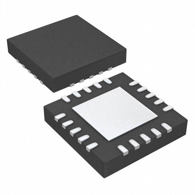


 工商网监
湘ICP备2023018690号
工商网监
湘ICP备2023018690号
