User's Guide
SLWU079D – March 2012 – Revised April 2016
TSW140x High Speed Data Capture/Pattern Generator
Card
The Texas Instruments TSW1400 Evaluation Module (EVM) is a next generation of pattern generator and
data capture card used to evaluate performances of a wide range of Texas Instruments (TI) high-speed
analog-to-digital converters (ADC) and digital-to-analog converters (DAC). For an ADC, capturing the
sampled data over an LVDS interface when using a high-quality, low-jitter clock, and a high-quality input
frequency, the TSW1400 can be used to demonstrate data sheet performance specifications. Together
with the accompanying LabVIEW™ based High Speed Data Converter Pro Graphic User Interface (HSDC
Pro GUI), it is a complete system that captures and evaluates data samples from ADC EVMs and
generates and sends desired test patterns to DAC EVMs.
The TSW1405 is a low cost data capture card with limited capabilities as compared with the TSW1400.
The TSW1405 supports pattern capture for most LVDS format TI ADC EVMs, but with a capture buffer
limitation of 64K samples. The TSW1405 draws its power from the USB connection to the PC for easy
setup and operation. HSDC Pro GUI supports the TSW1405 as well, making for a consistent feel across
the different platforms.
The TSW1406 is a low cost pattern generator card with limited capabilities as compared with the
TSW1400. The TSW1406 supports pattern generation for most LVDS format TI DAC EVMs, but with a
pattern limitation of 64K samples. The TSW1406 draws its power from the USB connection to the PC for
easy setup and operation. HSDC Pro GUI supports the TSW1406 as well.
This document describes the hardware aspect of the TSW140x EVMs along with a few quick start
examples of how to use these boards with ADC and DAC EVMs. For a thorough explanation of the
operation of the GUI, download the HSDC Pro GUI User's Guide (SLWU087) from the TI website.
Table 1. TSW140x EVM Features
Device
(1)
1
2
3
I/O Interface
16 Bit Memory Depth
Data Capture
Data Source
No
512M
Yes
Yes
No
64K
Yes
No
No
No
64K
No
Yes
No
Yes
512M
Yes
Yes
LVDS
CMOS
JESD
TSW1400
Yes
Yes
TSW1405
Yes
No
TSW1406
Yes
TSW14J56 (1)
No
See the TSW14J56 High-Speed Data Capture and Pattern Generator Card User's Guide (SLWU086) for information regarding
this board.
Contents
Functionality ..................................................................................................................
1.1
ADC EVM Data Capture ..........................................................................................
1.2
DAC EVM Pattern Generator .....................................................................................
Hardware Configuration .....................................................................................................
2.1
Power Connections .................................................................................................
2.2
Switches, Jumpers and Fuses ...................................................................................
2.3
LEDs ..................................................................................................................
2.4
Connectors ..........................................................................................................
Software Start up ............................................................................................................
3.1
Installation Instructions .............................................................................................
3.2
USB Interface and Drivers .........................................................................................
SLWU079D – March 2012 – Revised April 2016
Submit Documentation Feedback
TSW140x High Speed Data Capture/Pattern Generator Card
Copyright © 2012–2016, Texas Instruments Incorporated
3
4
4
5
5
5
6
6
8
8
9
1
�www.ti.com
4
5
6
7
8
3.3
Device ini Files.....................................................................................................
ADC Data Capture Software Operation ................................................................................
4.1
Testing a TSW1400 EVM with an ADS5281 EVM ............................................................
4.2
Testing a TSW1400EVM with an ADS62P49EVM (CMOS Interface)......................................
TSW1400 Pattern Generator Operation .................................................................................
5.1
Testing a TSW1400 EVM with a DAC3152 EVM .............................................................
5.2
Loading DAC Firmware ...........................................................................................
5.3
Configuring TSW1400 for Pattern Generation.................................................................
5.4
Testing a TSW1400 EVM with a DAC5688EVM (CMOS Interface) .......................................
TSW1405 Functional Description ........................................................................................
6.1
Hardware Description .............................................................................................
6.2
Software Operation ...............................................................................................
TSW1406 Functional Description ........................................................................................
7.1
Hardware Description .............................................................................................
7.2
Software Operation ...............................................................................................
Revision History ............................................................................................................
12
12
12
15
18
18
18
20
21
24
25
26
28
28
29
30
List of Figures
1
TSW1400EVM Block Diagram ............................................................................................. 3
2
TSW140x EVM Serial Number............................................................................................. 9
3
Firmware Does Not Match the Device Selected ......................................................................... 9
4
TSW140x EVM GUI Top Level ........................................................................................... 10
5
Connecting GUI to the EVM .............................................................................................. 10
6
Hardware Device Manager
7
TSW1400EVM Interfacing to an ADS5281 EVM....................................................................... 13
8
ADC5281 Single Tone FFT Capture Results ........................................................................... 14
9
Devices Supported with Current Firmware Loaded.................................................................... 15
10
TSW1400EVM Interfacing to the CMOS Connectors of an ADS62P49EVM
11
TSW1400EVM Captured Results from ADS62P49EVM .............................................................. 17
12
TSW1400 EVM Interfacing to a DAC EVM ............................................................................. 18
13
TSW1400EVM GUI DAC Mode Top Level
14
DAC Selection .............................................................................................................. 19
15
TSW1400 Output Data to DAC EVM .................................................................................... 20
16
TSW1400EVM Interfacing to the CMOS Connectors of a DAC5688EVM.......................................... 21
17
CDCM7005 Tab on DAC5688 GUI ...................................................................................... 22
18
GUI after Test File Loaded ................................................................................................ 23
19
DAC5688 IF Output ........................................................................................................ 24
20
TSW1405EVM Connected to the ADC Output of the AFE7225EVM
21
Number of Channels Selection ........................................................................................... 27
22
TSW1406EVM Connected to the DAC Input of the AFE7225EVM .................................................. 28
...............................................................................................
......................................
.............................................................................
...............................................
11
16
19
25
Trademarks
Microsoft, Windows are registered trademarks of Microsoft Corporation.
LabVIEW is a trademark of National Instruments Corporation.
All other trademarks are the property of their respective owners.
2
TSW140x High Speed Data Capture/Pattern Generator Card
SLWU079D – March 2012 – Revised April 2016
Submit Documentation Feedback
Copyright © 2012–2016, Texas Instruments Incorporated
�Functionality
www.ti.com
1
Functionality
The TSW1400 has two direct interfaces to TI ADC EVMs. One option captures data through a LVDS
interface and the other uses a CMOS interface. Sampled data from the ADC is de-serialized and
formatted by an Altera Stratix IV FPGA, then stored into an external onboard 1GByte DDR memory card.
The onboard memory enables the TSW1400 to store up to 512M 16 bit data samples. To acquire data on
a host PC, the FPGA reads the data from memory and transmits it on Serial Peripheral Interface (SPI). An
onboard high speed USB to SPI converter bridges the FPGA SPI interface to the host PC and GUI.
The TSW1400 has two direct interfaces to TI DAC EVMs. In Pattern Generator Mode, the TSW1400
generates desired test patterns for DAC EVMs under test. These patterns are sent from the host PC over
the USB interface to the TSW1400. The FPGA stores the data received into the board DDR memory
module. The data from the memory is then read by the FPGA and transmitted to a DAC EVM either
across a DAC LVDS interface connector or a CMOS interface connector.
A block diagram of the TSW1400 EVM is shown in Figure 1.
TSW1400 EVM
1GB DDR RAM
Data and Clock
Signals
SPI
Interface
Pattern and
Data Clock
DAC LVDS INTERFACE
ADC LVDS INTERFACE
ADC / DAC CMOS
INTERFACE
ALTERA
STRATIX IV
(FIRMWARE)
ADC
EVM
USB
to
SERIAL
USB
PORT
DAC
EVM
Figure 1. TSW1400EVM Block Diagram
SLWU079D – March 2012 – Revised April 2016
Submit Documentation Feedback
TSW140x High Speed Data Capture/Pattern Generator Card
Copyright © 2012–2016, Texas Instruments Incorporated
3
�Functionality
1.1
www.ti.com
ADC EVM Data Capture
Many TI high-speed ADCs have LVDS outputs for the digitized data. These ADCs are generally available
on an EVM that connects directly to the TSW1400EVM. The common connector between the ADC EVM
and the TSW1400EVM is a Samtec high-speed connector with differential pairs routed to adjacent pins
and the pairs separated by a ground pin. A common pinout for the connector across a family of EVMs has
been established. At present, the interface between the ADC EVM and the TSW1400EVM has defined
connections for 35 pairs of LVDS data lines, two clock pairs, and eight general purpose CMOS I/O pins.
The TSW1400 has a CMOS interface that provides 44 single ended connections to a two row, 88 pin, 100
mil center, female header style connector.
The data format for the LVDS data bus can be in one of many formats, all supported by the TSW1400.
For single-channel, high-speed ADCs, the data format is commonly a parallel dual-data rate with one
output clock . Dual-data rate means that both the rising and falling edges of the clock register data into the
TSW1400. For multichannel ADCs, the data is commonly presented in a serialized format, where
individual bits of the output data are presented on an LVDS pair one bit at a time, at a higher data rate
than the sample rate of the ADC.
Several firmware files are used by the FPGA on the TSW1400 to accommodate both parallel DDR formats
an serial LVDS formats, although not at the same time. The GUI will load the FPGA with the appropriate
firmware based on the ADC EVM under test selected by the user.
The parallel DDR FPGA program supports several types of data formats. One common format presents
odd-numbered data bits on the bus on one clock edge and even-numbered data bits on the bus on the
other clock edge. This format is commonly used for ADCs with sampling rates up to 250 MHz. For this bitwise DDR format, the parallel data bus uses half as many LVDS pairs as there are bits in the sample. For
example, a 16-bit ADC uses eight LVDS pairs for data plus an LVDS clock pair for bit-wise DDR. For
higher sample rates up to 1 GHz, a sample-wise DDR format is often used. For sample-wise DDR, the
data bus width has as many LVDS pairs as the bit resolution of the ADC. On one clock edge, a data
sample from the ADC is registered; on the next clock edge, the next data sample from the ADC is
registered.
The serial FPGA program also supports several data formats. For one-wire serial formats, the data is
serialized onto a single LVDS pair at a rate that is 12 times the sample rate for an ADC with a 12-bit
resolution. A one-wire serialization format also is used for 14-bit and 16-bit data at data rates 14 or 16
times the sample rate, respectively. For serial data formats, a DDR LVDS bit clock is used to strobe the
serial data bits and to de-serialize the data. An additional clock pair operating at the sample rate of the
ADC identifies the sample-word boundaries in the serial data. For multichannel ADCs, a single-bit clock
and a single sample-rate clock (frame clock) is used for all of the LVDS data channels. The other common
serial data format is two-wire serialization. Two-wire serialization is similar to one-wire serialization except
that a data channel uses two LVDS pairs to carry the serialized data at a rate that is half of what it is for
one-wire serialization.
1.2
DAC EVM Pattern Generator
Some TI high-speed DAC’s have LVDS inputs for the digitized data. These DACs are generally available
on an EVM that connects directly to the TSW1400EVM. The common connector between the DAC EVM
and the TSW1400EVM is a Samtec high-speed connector with differential pairs routed to adjacent pins
and the pairs separated by a ground pin. A common pinout for the connector across a family of EVMs has
been established. At present, the interface between these DAC EVMs and the TSW1400EVM has defined
connections for 32 pairs of LVDS data lines, two data output clock pairs, four control pairs, two input clock
pairs (sync, strobes, and so on), eight general purpose CMOS I/O pins (USB controlled) and 10 general
purpose CMOS I/O pins (FPGA controlled). The TSW1400 CMOS interface provides up to 40 singleended CMOS data outputs and two clock sources for CMOS DAC EVM formats. This interface has an
option to be either 3-V or 1.8-V CMOS logic.
4
TSW140x High Speed Data Capture/Pattern Generator Card
SLWU079D – March 2012 – Revised April 2016
Submit Documentation Feedback
Copyright © 2012–2016, Texas Instruments Incorporated
�Hardware Configuration
www.ti.com
2
Hardware Configuration
In this section, the various portions of the TSW1400EVM hardware are described.
2.1
Power Connections
The TSW1400EVM hardware is designed to operate from a single-supply voltage of 5 Vdc. The power
input is controlled by the ON/OFF switch SW7. Make sure this switch is in the “OFF” position before
inserting the power plug. Connect one end of the provided power cable to J12 of the EVM and the other
end to +5 VDC power supply capable of providing at least 4 amps.
2.1.1
Output Power Regulators
The TSW1400 provides two output power sources with these default settings:
• 3.3 V at 3 A at J10 and the return at J9
• 1.8 V at 6 A at J8 and the return to J9.
Both power supplies are derived from on-board switching power supplies and controlled by switch SW7.
See the TI TPS54620 (SLVS949) and TPS54325 data sheet (SLVS932) for more information regarding
the performance of these devices before deciding to use them to power up external EVMs.
2.2
2.2.1
Switches, Jumpers and Fuses
Switches and Pushbuttons
Switch SW7 is the main power ON/OFF switch.
Dipswitch SW1 has all switches routed to spare pins on the FPGA. Each switch trace has a pullup to 3.3
V and shorts this to ground when the switch is closed. Currently none of the switches are used.
Five pushbutton switches are mounted on the TSW1400EVM. One pushbutton switch currently has a
defined function; one of the other switches is reserved for future use.
The CPU_RESET (SW6) pushbutton causes the FPGA to reset the internal PLL logic.
2.2.2
Jumpers
Jumpers JP5, JP6, and JP7 allow the option to break the connection on three GPIO signals that are
routed between connector J3 and USB controller U3 through buffer U16. When the jumper shunts are
removed and buffer U16 is disabled, the user can provided external signals to three signals going to an
ADC EVM that is connected to J3 by using pin 1 of JP5, JP6, and JP7. Connecting pins 1 and 2 of
Jumper SJP1 will disable U16. Connecting pins 1 and 2 of Jumper SJP2 will disable U17, which is the
buffer providing the GPIO signals to the DAC EVM interface connector. See the TSW1400 EVM
schematic for more details.
Jumpers JP3 and JP4 set the output voltage of buffers U16 and U17. These buffers provide GPIO signals
between the TSW1400 and ADC and DAC EVMs. When set to pins 1-2, the buffers will provide 1.8-V
CMOS logic level signal interface to the ADC and DAC EVM connectors. When set to 2-3, the level will be
3 V. JP3 controls the ADC signals, and JP4 controls the DAC signals. See the TSW1400 EVM schematic
for more details.
Jumper JP8 sets the signal output voltage of CMOS_PORT1[19:1] bus on connector J1. When set to pins
1-2, the FPGA will provide 1.8-V CMOS logic level signals. When set to 2-3, the level will be 3 V.
SLWU079D – March 2012 – Revised April 2016
Submit Documentation Feedback
TSW140x High Speed Data Capture/Pattern Generator Card
Copyright © 2012–2016, Texas Instruments Incorporated
5
�Hardware Configuration
2.2.3
www.ti.com
Fuses
Fuse F1 is in line with the EVM input power. This is used along with diode D14 to protect the board from
surges and over voltage on the input power supply.
Fuse F2, when installed, will provide 6 VDC to the DAC EVM interface connector J4.
CAUTION
When using this 6 VDC for a DAC EVM, make sure the DAC EVM power
connection is removed.
2.3
LEDs
Eleven LEDs are on the TSW1400EVM to indicate the presence of power and the state of the FPGA.
The LED on the left edge of the board illuminates to indicate the presence of a 5-V power to the board
after SW7 is placed in the “ON” position.
LED D1 illuminates to indicate that the FPGA programming has completed and is now operational.
USER_LED0 and LED1 indicate transmission of data samples over SPI interface.
USER_LED2 turns off when the FPGA is in reset mode.
USER_LED3 indicates the FPGA PLL1 is locked to the ADC input clock from port 0.
USER_LED4 indicates the FPGA PLL2 is locked to the ADC input clock from port 1 or locked to the
FPGACLK from the DAC when in the DAC mode.
USER_LED5 indicates that the DDR memory initialization is complete and the interface is ready to
use.
USER_LED6 and LED7 indicate that the two SPI FIFO’s are empty.
LED D10 indicates the presence of 6-V power to the DAC EVM interface connector J4.
2.4
Connectors
The TSW1400 EVM has several connectors to allow for direct plug in of various TI CMOS and LVDS ADC
and DAC EVMs.
2.4.1
Input LVDS ADC Interface Connector
The connection between the TSW1400EVM and the ADC EVM to be tested is through a 128-pin High
speed Samtec connector. 35 LVDS data pairs plus two LVDS clock pairs have a defined position in the
connector pinout that is common between the TSW1400EVM and many TI ADC EVMs. For the parallel
LVDS DDR data format, the bit clock runs at the same rate as the sample clock to the ADC. For the serial
LVDS data format, the bit clock runs at a higher multiple of the ADC sample clock and is used to strobe
the serial data into the TSW1400EVM and then de-serialize the data. For the serial LVDS data format, a
second clock is provided, called the frame clock or FCLK, that runs at the sample rate and is used to
delineate the sample boundaries in the serial data stream. The frame clock line can be used as a second
clock in the parallel LVDS DDR format that uses two data buses. The data direction for the LVDS data
pairs is always defined as the ADC EVM driving the signal through the connector to the TSW1400EVM
FPGA, with integrated 100-Ω termination in the FPGA.
For one-channel parallel DDR bit-wise data formats, eight of the LVDS data pairs are used to support up
to 16-bit-resolution ADCs at up to 250-MHz sampling rates. For one-channel parallel DDR sample-wise
data formats, 14 of the LVDS data pairs are used to support up to 14-bit-resolution ADCs at up to 500MHz sampling rates. For two-channel parallel DDR bit-wise data formats, 14 of the LVDS data pairs are
used to support two channels of 14-bit resolution at up to 250-MHz sampling rate.
For serial data formats, eight of the LVDS data pairs support up to eight channels of one-wire serial ADCs
at up to 65-MHz sampling rate or four channels of two-wire serial ADCs at up to 125-MHz sampling rates.
Eight extra CMOS single-ended signals are defined in the Samtec connector that are sourced from the
USB interface through the connector to the ADC EVM. These signals, in the future, will allow the GUI to
control the SPI serial programming of the ADC for those ADC EVMs that support this feature.
6
TSW140x High Speed Data Capture/Pattern Generator Card
SLWU079D – March 2012 – Revised April 2016
Submit Documentation Feedback
Copyright © 2012–2016, Texas Instruments Incorporated
�Hardware Configuration
www.ti.com
The Samtec connectors snap together with no screws or other mechanism to hold the TSW1400EVM and
the ADC EVM together. The TSW1400EVM comes with standoff posts for setting the TSW1400EVM flat
on a bench or table. The ADC EVM has shorter standoff posts so that the TSW1400EVM and ADC EVM
will lay flat on a bench or table and stay snapped together during use.
2.4.2
JTAG Connector
The TSW1400EVM includes an industry-standard JTAG connector that connects to the JTAG ports of the
FPGA and the programming pins of the FPGA EEPROM. Jumpers on the TSW1400EVM allow for either
the FPGA or the FPGA EEPROM to be programmed from the JTAG chain. The JTAG connector is to be
used for trouble shooting only. The board default setup is with the FPGA JTAG pins connected to the USB
interface. This allows the FPGA to be programmed by the GUI though the USB interface. The current
design does not support the use of the FPGA EEPROM. Every time the TSW1400 EVM is powered down,
the FPGA configuration is removed. The user must program the FPGA through the GUI after every time
the board is powered up.
2.4.3
Input CMOS ADC Interface Connector
The connection between the TSW1400EVM and a CMOS ADC EVM to be tested is through a two row, 88
pin, 100 mil center, Samtec female header style connector (J1). The 40 single-ended data lines and two
clock lines have a defined position in the connector pinout that is common between the TSW1400EVM
and several TI CMOS ADC EVMs. The Samtec connectors couple together with no screws or other
mechanism to hold the TSW1400EVM and the ADC EVM together. The TSW1400EVM comes with
standoff posts for setting the TSW1400EVM flat on a bench or table. The ADC EVM has shorter standoff
posts so that the TSW1400EVM and ADC EVM will lay flat on a bench or table when connected together.
2.4.4
Output LVDS Connector
The connection between the TSW1400EVM and the DAC EVM to be tested is through a 192-pin High
speed Samtec connector. 32 LVDS output data pairs plus two LVDS output clock pairs, four differential
control pairs (sync, strobes, and so on), two input clock pairs, eight general purpose CMOS I/O pins (USB
controlled) and 10 general purpose CMOS I/O pins (FPGA controlled). These signals have a defined
position in the connector pinout that is common between the TSW1400EVM and many TI DAC EVMs.
2.4.5
Output CMOS DAC Interface Connector
The TSW1400EVM CMOS ADC Interface connector, J1, is also used to support several TI CMOS DAC
EVMs. The 40 single-ended data lines and two clock lines have a defined position in the connector pinout
that is common between the TSW1400EVM and several TI CMOS DAC EVMs. The Samtec connectors
couple together with no screws or other mechanism to hold the TSW1400EVM and the DAC EVM
together.
2.4.6
USB I/O Connection
Control of the TSW1400EVM is through a USB connection to a PC running the Microsoft® Windows®
operating system. For the computer, the drivers needed to access the USB port are included on the HSDC
Pro Software GUI installation software that can be downloaded from the web. The drivers are
automatically installed during the installation process. On the TSW1400EVM, the USB port is used to
identify the type and serial number of the EVM under test, load the desired FPGA configuration file,
capture data from ADC EVMs, and send test pattern data to the DAC EVMs.
On first connection of the USB port to a computer, the Microsoft Found New Hardware Wizard appears.
Follow the dialog box prompts as covered in the installation section of the HSDC Pro GUI User’s Guide
(SLWU087).
SLWU079D – March 2012 – Revised April 2016
Submit Documentation Feedback
TSW140x High Speed Data Capture/Pattern Generator Card
Copyright © 2012–2016, Texas Instruments Incorporated
7
�Software Start up
3
Software Start up
3.1
Installation Instructions
•
•
•
•
•
•
•
•
•
www.ti.com
Download the latest version of the HSDC Pro GUI (SLWC107) to a local location on a host PC. This
can be found on the TI website by entering “HIGH SPEED DATA CONVERTER PRO” or
"TSW1400EVM” in the search parameter window at www.ti.com.
Unzipping the software package will generate a folder called “High Speed Data Converter Pro Installer vx.xx.exe", where x.xx is the version number. Run this program to start the installation.
Follow the on-screen instructions during installation.
Make sure to disconnect all USB cables from any TSW140x boards before installing the software.
Click on the “Install” button. A new window opens. Click the “Next” button.
Accept the License Agreement. Click on the “Next” button to start the installation. After the installer has
finished, click the “Next” button one last time.
The installation is now complete. The GUI executable and associated files will reside in the following
directory:
C:\Program Files (x86)\Texas Instruments\High Speed Data Converter Pro.
Power up the TSW140x under test.
Start the GUI by clicking on the file called “High Speed Data Converter Pro.exe", located under
C:\Program Files\Texas Instruments\High Speed Data Converter Pro.
NOTE: If an older version of the GUI has already been installed, make sure to uninstall it before
loading a newer version. If the GUI detects that a newer version of the GUI is available
online (http://www.ti.com/tool/tsw1400evm), it will assist the user with downloading the latest
version from the TI website. The GUI automatically interrogates the product website for latest
version every seven days but the latest version check can also be manually invoked through
use of the pull-down menu Help->Check for updates.
NOTE: When new TI HSDC EVMs become available that are not supported with the current GUI
software release, the HSDC Pro GUI Updates executable, available on the TI website
(www.ti.com), will allow the user to add these EVMs to the GUI device list. Doing a search
for TSW1400EVM will direct the user to this location. The user should download this patch .
Start the application and follow the on screen instructions. The patch will display the files that
will be either added or replaced and have tabs for viewing what files will be deleted and
release notes. After running the patch, the user will then be able to start the High Speed
Data Converter Pro GUI and notice new parts added to the ADC and DAC device drop down
selection box. The patch is always specific to a core GUI version so the patch application
would not work for any GUI version that the patch was not explicitly created for.
8
TSW140x High Speed Data Capture/Pattern Generator Card
SLWU079D – March 2012 – Revised April 2016
Submit Documentation Feedback
Copyright © 2012–2016, Texas Instruments Incorporated
�Software Start up
www.ti.com
3.2
USB Interface and Drivers
The HSDC Pro GUI will first attempt to connect to the EVM USB interface. If the GUI identifies a valid
board serial number, a pop-up will open displaying this value, as shown in Figure 2. The serial number
also has an EVM type number attached to it. This indicates to the GUI which TSW140x board is presently
connected to the host PC. It is possible to connect several TSW140x EVMs to one host PC but the GUI
can only connect to one at a time. If multiple boards are connected to the PC, the pop-up displays all of
the serial numbers found. It is then up to the user to select which board the GUI will be associated with.
Figure 2. TSW140x EVM Serial Number
Click on “OK” to connect the GUI to the board. If the FPGA firmware version read by the GUI does not
match the firmware to be used as determined by the device selected (see section 4.1 for more info on
device selection), the following message appears as shown in Figure 3. This message also appears after
power up as the FPGA is not programmed.
Figure 3. Firmware Does Not Match the Device Selected
SLWU079D – March 2012 – Revised April 2016
Submit Documentation Feedback
TSW140x High Speed Data Capture/Pattern Generator Card
Copyright © 2012–2016, Texas Instruments Incorporated
9
�Software Start up
www.ti.com
Click on “OK”. The Top level GUI now opens and appears as shown in Figure 4.
vx.xxx
Figure 4. TSW140x EVM GUI Top Level
After the software has established a connection, if the message “Board not Connected” opens, double
check the USB cable connections and that power is present. If the cable connections appear fine, try
establishing a connection by clicking on the “Instrument Option” tab at the top left of the GUI and select
“Connect to the Board” (see Figure 5). If this still does not correct this issue, check the status of the host
USB port.
Figure 5. Connecting GUI to the EVM
10
TSW140x High Speed Data Capture/Pattern Generator Card
SLWU079D – March 2012 – Revised April 2016
Submit Documentation Feedback
Copyright © 2012–2016, Texas Instruments Incorporated
�Software Start up
www.ti.com
When the software has been installed and the USB cable has been connected to the TSW140x EVM and
the PC, the TSW140x USB serial converter should be located in the Hardware Device Manager under the
Universal Serial Bus controllers as shown in Figure 6. This is a quad device which is why there is an A, B,
C, and D USB Serial Converter shown. When the USB cable is removed, these four will no longer be
visible in the Device Manager. If the drivers are present in the Device Manager window and the software
still does not connect, cycle power to the board and repeat the steps above.
If the GUI starts up but freezes before it brings up the "Connected to Board" dialog, or takes an unusually
long time for other actions to occur, it is possible the USB being used from the host PC is operating at
USB 1.0 speeds. A common indication of this is when the status bar on the bottom left of the screen
keeps reading "Disable all Controls" upon loading the software without ever going to the "Connect Board
Dialog". The GUI is designed to run at USB 2.0 speeds and some computers have USB 1.0 ports on the
front panel and 2.0 on the back panel. Using the ports on the back of the PC if at all possible is
recommended.
The .exe file installs the FTDI drivers during software installation. If after connecting the USB cable and
Windows lists the board as an "unknown device", this could be caused by corrupted FTDI drivers being
installed on the computer. This happens in cases where the same computer has been used to interface
with previous products that used FTDI drivers. In this case, users are advised to download and install a
utility from FTDI at http://www.ftdichip.com/Support/Utilities/CDMUninstaller_v1.4.zip.
The help file for using this utility is found at:
http:/www.ftdichip.com/Support/Utilities/CDM_Uninst_GUI_Readme.html
Users will need to use the following hex values to uninstall previous versions of the ftdi drivers:
Vendor ID (VID): 0403
Product ID (PID): 6010
After removing the drivers for this PID and VID, re-connect the TSW140x USB cable and check if the
TSW140x ports get listed properly in Device Manager.
Figure 6. Hardware Device Manager
SLWU079D – March 2012 – Revised April 2016
Submit Documentation Feedback
TSW140x High Speed Data Capture/Pattern Generator Card
Copyright © 2012–2016, Texas Instruments Incorporated
11
�Software Start up
3.3
www.ti.com
Device ini Files
Included in the installation for the HSDC Pro GUI software is a subdirectory of ini files for each category of
ADC and DAC that is supported by the TSW140x EVMs. TI strongly recommends that these files are not
edited except at the factory. These files contain necessary information for the GUI software to properly
configure the TSW140x EVM FPGA registers for proper operation with the desired ADC or DAC EVM.
Some of the entries within the ini file are obvious, such as defining the bit resolution for a device as 11,
12, 14, or 16 bits. Other entries in the ini file define for the FPGA which LVDS pairs within the Samtec
connector define the data bus, and correct operation may not be possible if these entries are edited. The
use of ini files allows for new device types to be supported by the TSW140x EVM as they become
available without having to modify, re-release, or re-install the HSDC Pro GUI software. New device types
may be supported at a later date simply by adding a new ini file to the proper subdirectory.
4
ADC Data Capture Software Operation
4.1
Testing a TSW1400 EVM with an ADS5281 EVM
This section describes the operation when testing with an ADS5281 EVM that has a LVDS output
interface.
• Power down the TSW1400 if an ADC EVM is not installed.
• Connect J8 of the ADS5281 EVM to connector J3 of the TSW1400.
• Provide unpowered +5 VDC connections to J1 and return to J2 of the ADS5281 EVM.
• Provide a 1.5-VPP, 40-MHz sine-wave clock to J26 of the ADS5281 EVM.
• Provide a filter 5.1-MHz analog input to CH1.
• Power up the TSW1400 followed by the ADC EVM.
• Start up the HSDC Pro GUI as described in the Software Start Up section.
• The TSW1400 EVM connected to an ADS5281 EVM is shown in Figure 7
12
TSW140x High Speed Data Capture/Pattern Generator Card
SLWU079D – March 2012 – Revised April 2016
Submit Documentation Feedback
Copyright © 2012–2016, Texas Instruments Incorporated
�ADC Data Capture Software Operation
www.ti.com
Figure 7. TSW1400EVM Interfacing to an ADS5281 EVM
To setup the GUI to run in the data capture mode, click on the “ADC” tab in the top left side of the GUI.
Navigate to the device selection button located in the upper left side of the GUI, click on the drop down
arrow, then select “ADS5281”. After double clicking on this file, a pop-up will open asking “Do you want to
update the Firmware for ADC”. Click on “Yes”. The firmware will now start loading and take ~ 20 seconds
to complete. After the ADS5281 firmware load has completed, the FPGA_CONF_DONE LED will turn on
after the FPGA configured. The LEDs labeled USER_LED (0–7) will also be on except for USER_LED4.
NOTE:
•
•
•
•
•
•
•
If the TSW1400 is not receiving a valid clock from the ADC EVM, USER_LED3 will be off.
Use the “Test Selection” button to change the capture display to Single Tone.
Set the active channel setting to Channel 1/8.
Use the default Record Length value of 65,536.
Set the ADC Sampling Rate to 40 MHz.
Click on the Auto Calculation of Coherent Frequency function and Rectangular capture mode if using a
coherent input frequency. Otherwise, do not set this and use "Blackman" windowing mode.
Set the input frequency source to the new value in ADC Input Target Frequency that is generated by
the Auto Calculation of Coherent Frequency function.
Make sure the display mode is set to “Frequency”.
SLWU079D – March 2012 – Revised April 2016
Submit Documentation Feedback
TSW140x High Speed Data Capture/Pattern Generator Card
Copyright © 2012–2016, Texas Instruments Incorporated
13
�ADC Data Capture Software Operation
•
www.ti.com
Click on the “Capture” button to perform a data capture. The results should like similar to those shown
in Figure 8.
Figure 8. ADC5281 Single Tone FFT Capture Results
The user can now change other parameters and do another capture to observe the ADC outputs with
different frequencies, amplitudes, and in other formats such as codes, or bits.
After the firmware is loaded, if the user clicks the drop down arrow in the device selection window, the GUI
will indicate which ADC EVMs can be used with this firmware load by adding a black diamond in front of
the device name, as shown in Figure 9. If the user does not power down the TSW1400, any one of the
devices with a black diamond can be tested without doing another firmware load. The devices supported
with the current firmware are marked with a black diamond.
14
TSW140x High Speed Data Capture/Pattern Generator Card
SLWU079D – March 2012 – Revised April 2016
Submit Documentation Feedback
Copyright © 2012–2016, Texas Instruments Incorporated
�ADC Data Capture Software Operation
www.ti.com
Figure 9. Devices Supported with Current Firmware Loaded
4.2
Testing a TSW1400EVM with an ADS62P49EVM (CMOS Interface)
This section describes the operation when testing with an ADS62P49 EVM that is configured for CMOS
output interface.
• Power down the TSW1400 if an ADC EVM is not installed.
• Connect J1 and J2 of the ADS62P49 EVM to connector J1 of the TSW1400 EVM.
NOTE: Pin 1 of the TSW1400 connector plugs into pin 39 of J1 on the ADS62P49 EVM.
•
•
•
•
•
•
•
Provide unpowered +5 VDC connections to J10 and return to J12 of the ADS62P49 EVM.
Provide a 1.5-VPP, 150-MHz sine-wave clock to J19 of the ADS62P49 EVM. Make sure this clock is
within the frequency limits specified in the data sheet when operating in CMOS mode.
Provide a filtered 5.1-MHz analog input to CH1 (J6).
Power up the TSW1400 followed by the ADC EVM.
Setup the ADS62P49 EVM to operate in parallel mode, offset binary parallel CMOS output, and
internal reference.
Start up the HSDC Pro GUI as described in the Software Start Up section.
The TSW1400 EVM connected to the CMOS connectors of the ADS62P49 EVM is shown in Figure 10
SLWU079D – March 2012 – Revised April 2016
Submit Documentation Feedback
TSW140x High Speed Data Capture/Pattern Generator Card
Copyright © 2012–2016, Texas Instruments Incorporated
15
�ADC Data Capture Software Operation
www.ti.com
Figure 10. TSW1400EVM Interfacing to the CMOS Connectors of an ADS62P49EVM
To setup the GUI to run in the data capture mode, click on the “ADC” tab in the top left side of the GUI.
Navigate to the device selection button located in the upper left side of the GUI, click on the drop down
arrow, then select “ADS62p49_cmos”. After double clicking on this file, a pop-up will open asking “Do you
want to update the Firmware for ADC”. Click on “Yes”. The firmware starts loading which takes
approximately 20 seconds to complete. After the firmware load has completed, the FPGA_CONF_DONE
LED turns on after the FPGA is configured. The LEDs labeled USER_LED (0–7) should now all be on.
NOTE: If the TSW1400 is not receiving a valid clock from the ADC EVM, USER_LED3 and
USER_LED4 will be off.
16
TSW140x High Speed Data Capture/Pattern Generator Card
SLWU079D – March 2012 – Revised April 2016
Submit Documentation Feedback
Copyright © 2012–2016, Texas Instruments Incorporated
�ADC Data Capture Software Operation
www.ti.com
•
•
•
•
•
•
•
•
Use the “Test Selection” button to change the capture display to Single Tone.
Set the active channel setting to Channel 1/2.
Use the default Record Length value of 65,536.
Set the ADC Sampling Rate to 150 MHz.
Click on the Auto Calculation of Coherent Frequency function and Rectangular capture mode if using a
coherent input frequency. Otherwise, do not set this and use "Blackman" windowing mode.
Set the input frequency source to the new value in ADC Input Target Frequency that is generated by
the Auto Calculation of Coherent Frequency function.
Make sure the display mode is set to “Frequency”.
Click on the “Capture” button to perform a data capture. The results should like similar to those shown
in Figure 11.
Figure 11. TSW1400EVM Captured Results from ADS62P49EVM
SLWU079D – March 2012 – Revised April 2016
Submit Documentation Feedback
TSW140x High Speed Data Capture/Pattern Generator Card
Copyright © 2012–2016, Texas Instruments Incorporated
17
�TSW1400 Pattern Generator Operation
www.ti.com
5
TSW1400 Pattern Generator Operation
5.1
Testing a TSW1400 EVM with a DAC3152 EVM
This section describes the pattern generator operation when testing with a DAC3152 EVM that has a
LVDS input interface.
• Power down the TSW1400.
• Connect J5 of the DAC3152 to connector J4 of the TSW1400.
• Provide +5 VDC to J12 and return to J13 of the DAC3152 EVM.
• Provide a 0.5-Vrms, 250-MHz clock to J9 of the DAC3152 EVM.
• Power up the TSW1400 EVM
• Start up the HSDC Pro GUI as described in the Software Start Up.
• A TSW1400 EVM connected to a DAC3152 EVM is shown in Figure 12.
Figure 12. TSW1400 EVM Interfacing to a DAC EVM
NOTE: The FPGA clocks from DAC EVMs to the TSW1400 EVM have to be LVDS level. Exceeding
LVDS levels may damage the TSW1400 FPGA.
5.2
Loading DAC Firmware
If opening the GUI for the first time, when setting up for pattern generator mode, make sure “DAC” in the
top right side of the GUI is selected. After clicking on “DAC”, the top level GUI shall look as shown in
Figure 13.
18
TSW140x High Speed Data Capture/Pattern Generator Card
SLWU079D – March 2012 – Revised April 2016
Submit Documentation Feedback
Copyright © 2012–2016, Texas Instruments Incorporated
�TSW1400 Pattern Generator Operation
www.ti.com
Figure 13. TSW1400EVM GUI DAC Mode Top Level
To run the GUI in DAC pattern generator mode, the FPGA must be loaded with the proper firmware, which
is determined by the DAC type to be tested.
In the “Select DAC” button of the GUI, click on the drop down arrow and select the DAC3152 (Figure 14).
This will be the targeted EVM for this test example.
Figure 14. DAC Selection
Click on “Yes” when asked “Do you want to update the firmware for DAC”. The firmware for this setup will
now be loaded during this process, which will take approximately 20 seconds. After the firmware load has
completed, the LEDs labeled USER_LED (0–7) will now turn on except for USER_LED 3 and 5.
USER_LED 3 is used to indicate the status of a second PLL, which is not used with this firmware build,
and USER_LED 5 indicates if there is a FIFO overflow (error) of the transmit data.
SLWU079D – March 2012 – Revised April 2016
Submit Documentation Feedback
TSW140x High Speed Data Capture/Pattern Generator Card
Copyright © 2012–2016, Texas Instruments Incorporated
19
�TSW1400 Pattern Generator Operation
www.ti.com
NOTE: If the TSW1400 is not receiving a valid clock from the DAC EVM, USER_LED3 and
USER_LED4 will be off.
5.3
Configuring TSW1400 for Pattern Generation
For this test, at the top of the GUI, set the following parameters:
• Preamble to 0
• Data Rate – 250 MSPS
• DAC Option – Offset Binary
• Active Channel – Channel 1
• Analysis Window (samples) – 32,768
• Window - Rectangular
• Format - Complex
The pattern generation data file should match one of the Record Length’s to us the Rectangular window
mode. If it does not, switch the window mode to another setting such as “Hanning”.
• Click on the button labeled “Load File to transfer into TSW1400”.
• Select “single_tone_cmplx_32768_250MSPS_BW_25.1MHZ.csv”.
• Click on “Send”.
The display panel of the GUI will be updated, showing the test data that will be transmitted to the DAC
EVM in both codes and frequency domain as shown in Figure 15.
Figure 15. TSW1400 Output Data to DAC EVM
20
TSW140x High Speed Data Capture/Pattern Generator Card
SLWU079D – March 2012 – Revised April 2016
Submit Documentation Feedback
Copyright © 2012–2016, Texas Instruments Incorporated
�TSW1400 Pattern Generator Operation
www.ti.com
Using a spectrum analyzer, verify that there is now a 25.1-MHz tone present on both SMA J2 (IOUTA2)
and J3 (IOUTB2) of the DAC3152 EVM.
To shut down the GUI, click on the “File” tab in the upper right corner of the GUI and select “Exit” in the
pop up window that opens. This will specify that the USB ports are released by the software.
5.4
Testing a TSW1400 EVM with a DAC5688EVM (CMOS Interface)
This section describes the operation when testing with a DAC5688EVM that has a CMOS input interface.
• Power down the TSW1400 if the DAC5688EVM is not installed.
NOTE: J1 pin 1 of the TSW1400 connector plugs into J2 pin 1 on the DAC5688EVM
•
•
•
•
•
•
•
•
•
Provide unpowered +3.3 VDC connections to J15 and return to J16 of the DAC5688EVM.
Provide unpowered +1.8 VDC connections to J13 and return to J14 of the DAC5688EVM.
Provide a USB cable between the DAC5688EVM and a host PC.
Provide an external sinewave source at 491.52 MHz with a 1-Vrms, 0-V offset to SMA J20
(EXT_VCXO) of the DAC5688EVM.
Connect a SMA cable from OUTCLK3 connector (J17) of the DAC5688EVM to CMOS_CLK (J7) of the
TSW1400 EVM.
Power up the TSW1400 followed by the DAC EVM.
Load and start up the DAC5688EVM GUI as described in the DAC5688EVM User’s Guide. The
software and User’s Guide can be found at http://www.ti.com/tool/dac5688evm.
Start up the HSDC Pro GUI as described in the Software Start Up section.
The TSW1400 EVM connected to the CMOS connectors of the DAC5688EVM is shown in Figure 16.
Figure 16. TSW1400EVM Interfacing to the CMOS Connectors of a DAC5688EVM
SLWU079D – March 2012 – Revised April 2016
Submit Documentation Feedback
TSW140x High Speed Data Capture/Pattern Generator Card
Copyright © 2012–2016, Texas Instruments Incorporated
21
�TSW1400 Pattern Generator Operation
www.ti.com
Using the DAC5688EVM GUI, load the EVM with the test file called “example”. This can be found at
C:\Program Files\Texas Instruments\DAC5688\DAC5688 Configuration Files. This sets up the DAC5688
to receive a WCDMA test pattern from the TSW1400 with a data rate of 122.88 MHz. CLK2 of DAC5688
operates at 491.52 MHz and the DAC interpolation is set to 4x, requiring the input data rate to be at
122.88 MHz.
In the DAC5688 GUI, go to the CDCM7005 tab and set the Y3 Output (OUTCLK3) to divide by 4,
LVCMOS, and inverting per Figure 17.
Figure 17. CDCM7005 Tab on DAC5688 GUI
This generates an inverted 122.88-MHz clock used by the TSW1400 to generate the CMOS test pattern.
NOTE: The CMOS data rate for the TSW1400 EVM should never exceed 250 MHz. This rate is set
by the CMOS_CLOCK input provide to J7. When operating at frequencies near this limit, the
user may need to adjust the delay of this signal to meet the timing specs of the DAC under
test.
On the DAC5688EVM, there is an option to use a spare output of the CDCM7005 clock
generator as a clock source. In this example, the OUTCLK3 of the CDCM7005 is inverted for
optimized setup and hold time. Another way to adjust the delay is to use different cable
lengths for this clock source.
If opening the HSDC Pro GUI for the first time, when setting up for pattern generator mode, make sure
“DAC” in the top right side of the GUI is selected. This targets the EVM for this test example. In the “Select
DAC” button of the GUI, click on the drop down arrow and select “cmos”. This firmware is used by most
High Speed CMOS DAC EVMs.
Click on “Yes” when asked “Do you want to update the firmware for DAC”. The firmware setup is loaded
during this process, which takes approximately 20 seconds. After the firmware load has completed, the
LEDs labeled USER_LED (0–7) will now turn on except for USER_LED 5. USER_LED 3 is used to
indicate the status of a second PLL, and USER_LED 5 indicates if there is a FIFO overflow (error) of the
transmit data.
NOTE: If the TSW1400 is not receiving a valid clock from the DAC EVM, USER_LED3 and
USER_LED4 are off.
22
TSW140x High Speed Data Capture/Pattern Generator Card
SLWU079D – March 2012 – Revised April 2016
Submit Documentation Feedback
Copyright © 2012–2016, Texas Instruments Incorporated
�TSW1400 Pattern Generator Operation
www.ti.com
For this test, at the top of the GUI, set the following parameters:
• Preamble to 0
• Data Rate – 122.88M (MSPS)
• DAC Option – 2’s Comp
• Active Channel – Channel 1
• Format – Complex
• Analysis Window (samples) - 65536
• Click on the button labeled “Load File to transfer into TSW1400”.
• Select “WCDMA_TM1_complexIF30MHz_Fdata122.88MHz_1000.csv”.
• Click on “Send”.
The display panel of the GUI is updated, showing the test data that is transmitted to the DAC EVM in both
codes and frequency domain as shown in Figure 18.
Figure 18. GUI after Test File Loaded
If the DAC5688EVM is configured for IF output, connect a spectrum analyzer to either SMA J4 (IOUTB2)
or J9 (IOUTA2) of the EVM. The DAC example file has a NCO setting of 61.44 MHz and the test pattern
IF is centered at 30 MHz. The signal should be a single carrier centered around 91.44 MHz, as shown in
Figure 19.
NOTE: The DAC5688EVM has the default setup as RF output. The modulator output location will be
at the LO frequency plus 91.44 MHz. For details about IF and RF output configuration
settings, see section 4.7 of the DAC5688EVM User’s Guide (SLAU241).
SLWU079D – March 2012 – Revised April 2016
Submit Documentation Feedback
TSW140x High Speed Data Capture/Pattern Generator Card
Copyright © 2012–2016, Texas Instruments Incorporated
23
�TSW1405 Functional Description
www.ti.com
Figure 19. DAC5688 IF Output
6
TSW1405 Functional Description
The TSW1405 Capture Card is a lower cost capture card than the TSW1400, with reduced memory
capacity for storing samples captured from TI High Speed ADC EVMs. The TSW1405 has a Samtec
connector to directly connect to the LVDS data bus from the EVM. The TSW1405 does not have
connections for CMOS ADC EVMs. The TSW1405 uses the same software GUI as the TSW1400.
The TSW1405 does not have an EEPROM resident on the board to hold an FPGA bit file, but rather will
get the bit file downloaded from the software GUI running on a PC at runtime. In this manner the
TSW1405 will not need to be reprogrammed when new ADC EVMs or additional capture features become
available. The planned FPGA firmware upgrades consists of new files to be downloaded to the software
GUI. The TSW1405 does have a footprint for a firmware EEPROM to be installed, if desired.
24
TSW140x High Speed Data Capture/Pattern Generator Card
SLWU079D – March 2012 – Revised April 2016
Submit Documentation Feedback
Copyright © 2012–2016, Texas Instruments Incorporated
�TSW1405 Functional Description
www.ti.com
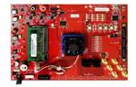
Figure 20. TSW1405EVM Connected to the ADC Output of the AFE7225EVM
6.1
6.1.1
Hardware Description
Power Connections
The TSW1405 draws its power supply from the 5-V source of the USB connection, so no additional
external power supply is needed in most applications. For applications where the USB connection does
not supply the 5 V, there is the option to connect an external 5-V supply to the test point loop labeled as
TP2, 5 V. To use the 5-V test point loop, it may be necessary to remove the surface mount zero-ohm
resistor in location R42 to disconnect the board’s 5-V supply from the USB connector.
6.1.2
Pushbuttons
The TSW1405 has provisions for two pushbutton switches which are normally not installed. SW1 causes
the FPGA to load its bit file from the on-board SPI Flash EEPROM. Since the EEPROM is normally not
installed, the pushbutton switch SW1 is normally not installed. Pushbutton switch SW2 is reserved for
possible future use, so it is also not installed at present.
SLWU079D – March 2012 – Revised April 2016
Submit Documentation Feedback
TSW140x High Speed Data Capture/Pattern Generator Card
Copyright © 2012–2016, Texas Instruments Incorporated
25
�TSW1405 Functional Description
6.1.3
www.ti.com
Jumpers
The TSW1405 has provisions for four jumpers which are normally not installed. Each jumper has one post
connected to an FPGA input and a pull up resistor while the other post connects to ground. These
jumpers are reserved for possible future use for setting options to the FPGA or for possible output
connections from the FPGA.
The TSW1405 also has an optional 6-pin header for connection to the JTAG port of the FPGA, but the
JTAG header may not be installed. The JTAG port would allow the use of an FPGA programming pod, but
is not necessary since the FPGA firmware is downloaded from the PC at runtime.
6.1.4
LEDs
The TSW1405 has an LED labeled D1 Done that is lit when the FPGA is finished loading a bit file and is
ready for use. An additional LED labeled D2 is normally not installed and is reserved for future use. For
the initial release of the TSW1405, the LED D2 (if installed) will flash when an LVDS clock is present from
the ADC EVM.
6.2
Software Operation
The TSW1405 uses the same software GUI as the TSW1400, providing for a consistent and familiar
experience for the user of the TI Capture Cards. When the GUI is launched on the PC, the GUI will detect
whether any TSW1400 or TSW1405 capture cards are connected to the PC USB ports, and allow the user
to select which to connect to if there are more than one connected.
26
TSW140x High Speed Data Capture/Pattern Generator Card
SLWU079D – March 2012 – Revised April 2016
Submit Documentation Feedback
Copyright © 2012–2016, Texas Instruments Incorporated
�TSW1405 Functional Description
www.ti.com
6.2.1
Channel Selection
Because the TSW1405 has limited memory for sample capture, the GUI makes provision for selecting the
number of channels from which to capture samples. This is a feature in the GUI that is not needed for the
TSW1400, so there is a GUI popup dialog box for the TSW1405 that is not used for the TSW1400, as
shown in Figure 21.
If a device is selected in the GUI that has more than one channel available, the Channel Selection Dialog
window will let the user select one or more channels to be used for capture. If two, four or eight channels
are selected, then samples from those channels are captured into the capture memory simultaneously.
Figure 21. Number of Channels Selection
The TSW1405 has enough internal memory in the FPGA to capture as many as 65536 samples of 16bit
data. The 65536 samples will be automatically allocated to one, two, four or eight channels depending on
the channel selections set in the GUI. If one channel is selected for capture, then the record length for that
channel will be 65536 samples. If two channels are selected for capture, then each channel will get a
record length of 32768 samples. Four channels will cause a record length of 16384 samples to be
captured for each channel, and eight channels will capture 8192 samples for each channel.
SLWU079D – March 2012 – Revised April 2016
Submit Documentation Feedback
TSW140x High Speed Data Capture/Pattern Generator Card
Copyright © 2012–2016, Texas Instruments Incorporated
27
�TSW1406 Functional Description
7
www.ti.com
TSW1406 Functional Description
The TSW1406 Pattern Generator Card is a low cost pattern generator card with reduced memory capacity
for providing test patterns to TI High Speed DAC EVMs. The TSW1406 has a High Speed Samtec
connector that directly connects to the LVDS input data bus of DAC EVM. The TSW1406 does not have
connections for CMOS DAC EVMs. The TSW1406 uses the same software GUI as the TSW1400.
The TSW1406 does not have an EEPROM resident on the board to hold an FPGA bit file, but rather will
get the bit file downloaded from the software GUI running on a PC at runtime. In this manner the
TSW1406 will not need to be reprogrammed when new DAC EVMs or additional capture features become
available. The planned FPGA firmware upgrades consists of new files to be downloaded to the software
GUI. The TSW1406 does have a footprint for a firmware EEPROM to be installed, if desired.
Figure 22. TSW1406EVM Connected to the DAC Input of the AFE7225EVM
7.1
7.1.1
Hardware Description
Power Connections
The TSW1406 draws its power supply from the 5-V source of the USB connection, so no additional
external power supply is needed in most applications. For applications where the USB connection does
not supply the 5 V, there is the option to connect an external 5-V supply to the test point loop labeled as
TP2 and GND to TP1. To use the 5-V test point loop, make sure to remove R42 to disconnect the board’s
5-V supply from the USB connector.
7.1.2
Pushbuttons
The TSW1406 has provisions for two pushbutton switches. SW1 causes the FPGA to load its bit file from
the on-board SPI Flash EEPROM. This mode is currently not supported. Pushbutton switch SW2 is
reserved for possible future use.
28
TSW140x High Speed Data Capture/Pattern Generator Card
SLWU079D – March 2012 – Revised April 2016
Submit Documentation Feedback
Copyright © 2012–2016, Texas Instruments Incorporated
�TSW1406 Functional Description
www.ti.com
7.1.3
Jumpers
The TSW1406 has provisions for four jumpers which are normally not installed. Each jumper has one post
connected to an FPGA input and a pull up resistor while the other post connects to ground. These
jumpers are reserved for possible future use for setting options to the FPGA or for possible output
connections from the FPGA. The TSW1406 also has an optional 6-pin header for connection to the JTAG
port of the FPGA. The JTAG port would allow the use of an FPGA programming pod, but is not necessary
since the FPGA firmware is downloaded from the PC at runtime.
7.1.4
LEDs
The TSW1406 LED labeled D1 is the “Done” indicator of the FPGA. This LED is lit when the FPGA is
finished loading a bit file and is ready for use. An additional LED labeled D2 represents PLL lock status of
the FPGA which should be on for normal operation.
7.2
Software Operation
The TSW1406 uses the same software GUI as the TSW1400, providing for a consistent and familiar
experience for the user of the TI Pattern Generator Cards. When the GUI is launched on the PC, the GUI
detects whether any TSW1400, TSW1405, or TSW1406 capture cards are connected to the PC USB
ports, and allow the user to select which to connect to if there are more than one connected.
SLWU079D – March 2012 – Revised April 2016
Submit Documentation Feedback
TSW140x High Speed Data Capture/Pattern Generator Card
Copyright © 2012–2016, Texas Instruments Incorporated
29
�Revision History
8
www.ti.com
Revision History
Revision A (March 2012)
Changed and Added figures and text throughout the document
Added section 7 - TSW1405 Functional Description
Revision B (September 2012)
The GUI supports the TSW1406 Low Cost pattern Generation card in addition to the TSW1400 and TSW1405.
Master and slave triggering modes are available for the TSW1400. Under 'Data Capture Option' there is now a 'Trigger Option'
menu with two sub-options. 'Trigger Mode Enable' allows externally triggering capture into DDR memory through SMA connector
named 'EXT_TRG_IN' while 'Software Trigger' generates a trigger on the four SMA connectors labeled 'SYNC'
Added FFT Averaging feature (with or without continuous capture). This feature performs 'n' continuous captures (max = 10) and
averages the FFT's on the fly to reduce noise
Complex FFT feature is now available for the DAC panel. The 'format' dropdown above the FFT plot controls whether the FFT is
visualized in real or complex mode.
Includes ‘DAC channel enable’ feature that allows one to selectively send zeroes to selected DAC channels
Increased speed of Continuous Capture function.
The notch frequency bins menu option is disabled in all modes except single tone.
Revised defaults for notch filters ( 25:25:25) in windowed modes only. Rectangular window modes filter parameters unchanged.
Peak to Peak amplitude and PAR values are now displayed for time domain DAC and ADC.
FFT plot in DAC mode defaults to windowed (Blackman window) mode when creating tone or loading file with >64K samples.
The Time domain plot color is now dark blue (both on the context plot and main plots).
Test Options tab added option to display the X axis scale in "time" instead of "Samples".
The Bandwidth Integration Markers could earlier be swapped, causing problems. Now they cannot.
GUI auto-disconnects gracefully if the USB cable is unplugged and some user operation is attempted.
GUI includes a "Check for Updates" feature that checks (every 7 days) for latest version and prompts a download if a newer
version is available for download at the TI product page. Feature is also accessible from menu.
Advanced "FFT x scale" feature in Device INI to adjust the FFT x scale for decimated sample rate devices.
Revision C (December 2013)
Added TSW14J56 information to Table 1.
Replaced section 3, "Software Start Up", with section of the same name from High Speed Data Converter Pro GUI (SLWU087).
Removed section 4, "User Interface".
Replaced section 5, "ADC Data Capture Software Operation", with section of the same name from High Speed Data Converter Pro
GUI (SLWU087).
Replaced section 6, "TSW1400 Pattern Generator Operation", with section of the same name from High Speed Data Converter Pro
GUI (SLWU087).
Revision D (April 2016)
Changed 1st paragraph of the Power Connections section.
30
TSW140x High Speed Data Capture/Pattern Generator Card
SLWU079D – March 2012 – Revised April 2016
Submit Documentation Feedback
Copyright © 2012–2016, Texas Instruments Incorporated
�IMPORTANT NOTICE FOR TI DESIGN INFORMATION AND RESOURCES
Texas Instruments Incorporated (‘TI”) technical, application or other design advice, services or information, including, but not limited to,
reference designs and materials relating to evaluation modules, (collectively, “TI Resources”) are intended to assist designers who are
developing applications that incorporate TI products; by downloading, accessing or using any particular TI Resource in any way, you
(individually or, if you are acting on behalf of a company, your company) agree to use it solely for this purpose and subject to the terms of
this Notice.
TI’s provision of TI Resources does not expand or otherwise alter TI’s applicable published warranties or warranty disclaimers for TI
products, and no additional obligations or liabilities arise from TI providing such TI Resources. TI reserves the right to make corrections,
enhancements, improvements and other changes to its TI Resources.
You understand and agree that you remain responsible for using your independent analysis, evaluation and judgment in designing your
applications and that you have full and exclusive responsibility to assure the safety of your applications and compliance of your applications
(and of all TI products used in or for your applications) with all applicable regulations, laws and other applicable requirements. You
represent that, with respect to your applications, you have all the necessary expertise to create and implement safeguards that (1)
anticipate dangerous consequences of failures, (2) monitor failures and their consequences, and (3) lessen the likelihood of failures that
might cause harm and take appropriate actions. You agree that prior to using or distributing any applications that include TI products, you
will thoroughly test such applications and the functionality of such TI products as used in such applications. TI has not conducted any
testing other than that specifically described in the published documentation for a particular TI Resource.
You are authorized to use, copy and modify any individual TI Resource only in connection with the development of applications that include
the TI product(s) identified in such TI Resource. NO OTHER LICENSE, EXPRESS OR IMPLIED, BY ESTOPPEL OR OTHERWISE TO
ANY OTHER TI INTELLECTUAL PROPERTY RIGHT, AND NO LICENSE TO ANY TECHNOLOGY OR INTELLECTUAL PROPERTY
RIGHT OF TI OR ANY THIRD PARTY IS GRANTED HEREIN, including but not limited to any patent right, copyright, mask work right, or
other intellectual property right relating to any combination, machine, or process in which TI products or services are used. Information
regarding or referencing third-party products or services does not constitute a license to use such products or services, or a warranty or
endorsement thereof. Use of TI Resources may require a license from a third party under the patents or other intellectual property of the
third party, or a license from TI under the patents or other intellectual property of TI.
TI RESOURCES ARE PROVIDED “AS IS” AND WITH ALL FAULTS. TI DISCLAIMS ALL OTHER WARRANTIES OR
REPRESENTATIONS, EXPRESS OR IMPLIED, REGARDING TI RESOURCES OR USE THEREOF, INCLUDING BUT NOT LIMITED TO
ACCURACY OR COMPLETENESS, TITLE, ANY EPIDEMIC FAILURE WARRANTY AND ANY IMPLIED WARRANTIES OF
MERCHANTABILITY, FITNESS FOR A PARTICULAR PURPOSE, AND NON-INFRINGEMENT OF ANY THIRD PARTY INTELLECTUAL
PROPERTY RIGHTS.
TI SHALL NOT BE LIABLE FOR AND SHALL NOT DEFEND OR INDEMNIFY YOU AGAINST ANY CLAIM, INCLUDING BUT NOT
LIMITED TO ANY INFRINGEMENT CLAIM THAT RELATES TO OR IS BASED ON ANY COMBINATION OF PRODUCTS EVEN IF
DESCRIBED IN TI RESOURCES OR OTHERWISE. IN NO EVENT SHALL TI BE LIABLE FOR ANY ACTUAL, DIRECT, SPECIAL,
COLLATERAL, INDIRECT, PUNITIVE, INCIDENTAL, CONSEQUENTIAL OR EXEMPLARY DAMAGES IN CONNECTION WITH OR
ARISING OUT OF TI RESOURCES OR USE THEREOF, AND REGARDLESS OF WHETHER TI HAS BEEN ADVISED OF THE
POSSIBILITY OF SUCH DAMAGES.
You agree to fully indemnify TI and its representatives against any damages, costs, losses, and/or liabilities arising out of your noncompliance with the terms and provisions of this Notice.
This Notice applies to TI Resources. Additional terms apply to the use and purchase of certain types of materials, TI products and services.
These include; without limitation, TI’s standard terms for semiconductor products http://www.ti.com/sc/docs/stdterms.htm), evaluation
modules, and samples (http://www.ti.com/sc/docs/sampterms.htm).
Mailing Address: Texas Instruments, Post Office Box 655303, Dallas, Texas 75265
Copyright © 2018, Texas Instruments Incorporated
�


 工商网监
湘ICP备2023018690号
工商网监
湘ICP备2023018690号
