CY8CKIT-019
PSoC® Shield Adapter Kit Guide
Doc. #: 001-90332 Rev. **
Cypress Semiconductor
198 Champion Court
San Jose, CA 95134-1709
Phone (USA): +1.800.858.1810
Phone (Intnl): +1.408.943.2600
http://www.cypress.com
�Copyrights
Copyrights
© Cypress Semiconductor Corporation, 2013. The information contained herein is subject to change without notice. Cypress
Semiconductor Corporation assumes no responsibility for the use of any circuitry other than circuitry embodied in a Cypress
product. Nor does it convey or imply any license under patent or other rights. Cypress products are not warranted nor
intended to be used for medical, life support, life saving, critical control or safety applications, unless pursuant to an express
written agreement with Cypress. Furthermore, Cypress does not authorize its products for use as critical components in lifesupport systems where a malfunction or failure may reasonably be expected to result in significant injury to the user. The
inclusion of Cypress products in life-support systems application implies that the manufacturer assumes all risk of such use
and in doing so indemnifies Cypress against all charges.
Any Source Code (software and/or firmware) is owned by Cypress Semiconductor Corporation (Cypress) and is protected by
and subject to worldwide patent protection (United States and foreign), United States copyright laws and international treaty
provisions. Cypress hereby grants to licensee a personal, non-exclusive, non-transferable license to copy, use, modify, create
derivative works of, and compile the Cypress Source Code and derivative works for the sole purpose of creating custom software and or firmware in support of licensee product to be used only in conjunction with a Cypress integrated circuit as specified in the applicable agreement. Any reproduction, modification, translation, compilation, or representation of this Source
Code except as specified above is prohibited without the express written permission of Cypress.
Disclaimer: CYPRESS MAKES NO WARRANTY OF ANY KIND, EXPRESS OR IMPLIED, WITH REGARD TO THIS MATERIAL, INCLUDING, BUT NOT LIMITED TO, THE IMPLIED WARRANTIES OF MERCHANTABILITY AND FITNESS FOR A
PARTICULAR PURPOSE. Cypress reserves the right to make changes without further notice to the materials described
herein. Cypress does not assume any liability arising out of the application or use of any product or circuit described herein.
Cypress does not authorize its products for use as critical components in life-support systems where a malfunction or failure
may reasonably be expected to result in significant injury to the user. The inclusion of Cypress’ product in a life-support systems application implies that the manufacturer assumes all risk of such use and in doing so indemnifies Cypress against all
charges.
Use may be limited by and subject to the applicable Cypress software license agreement.
PSoC and CapSense are registered trademarks and PSoC Creator is a trademark of Cypress Semiconductor Corp. All other
trademarks or registered trademarks referenced herein are property of the respective corporations.
Flash Code Protection
Cypress products meet the specifications contained in their particular Cypress PSoC Data Sheets. Cypress believes that its
family of PSoC products is one of the most secure families of its kind on the market today, regardless of how they are used.
There may be methods, unknown to Cypress, that can breach the code protection features. Any of these methods, to our
knowledge, would be dishonest and possibly illegal. Neither Cypress nor any other semiconductor manufacturer can guarantee the security of their code. Code protection does not mean that we are guaranteeing the product as ‘unbreakable’.
Cypress is willing to work with the customer who is concerned about the integrity of their code. Code protection is constantly
evolving. We at Cypress are committed to continuously improving the code protection features of our products.
CY8CKIT-019 PSoC Shield Adapter Kit Guide, Doc. #: 001-90332 Rev. **
2
�Contents
1. Introduction
1.1
1.2
1.3
1.4
1.5
Kit Contents .................................................................................................................4
Getting Started.............................................................................................................5
Additional Learning Resources....................................................................................5
Technical Support........................................................................................................5
Document Conventions ...............................................................................................5
2. Software Installation
2.1
2.2
2.3
2.4
15
Board Details .............................................................................................................15
Theory of Operation...................................................................................................15
Functional Description ...............................................................................................16
4.3.1 PSoC 4...........................................................................................................16
4.3.2 Power Supply System ....................................................................................16
4.3.3 Arduino Compatible Headers (J1, J2, J3, J4, and J12)..................................17
4.3.4 PSoC 5LP Header (J8) ..................................................................................18
4.3.5 Expansion Board Kit Adapter Header (J10) ...................................................18
4.3.6 Prototyping Connector (J9) ............................................................................20
4.3.7 Push Buttons..................................................................................................20
4.3.8 User LEDs......................................................................................................21
4.3.9 10K-Ohm Rotary Potentiometer.....................................................................21
4.3.10 Thermistor ......................................................................................................22
A. Appendix
A.1
A.2
11
Connecting the Shield Adapter Kit to the PSoC 4 Pioneer Kit ...................................12
Loading the First PSoC Shield Adapter Project .........................................................12
4. Hardware
4.1
4.2
4.3
6
Kit Software .................................................................................................................6
Install Hardware...........................................................................................................8
Uninstall Software........................................................................................................8
Open a Code Example Project in PSoC Creator .........................................................9
3. Kit Operation
3.1
3.2
4
23
PSoC Shield Adapter Kit Schematics ........................................................................23
Bill of Materials ..........................................................................................................27
CY8CKIT-019 PSoC Shield Adapter Kit Guide, Doc. #: 001-90332 Rev. **
3
�1.
Introduction
Thank you for your interest in the CY8CKIT-019 PSoC® Shield Adapter Kit. This kit is designed to be
used with the Cypress CY8CKIT-042 PSoC 4 Pioneer Kit. The kit supports the pin layout and header
profile of the PSoC 4 Pioneer Kit.
This kit is designed to provide simple user interfaces and integration with the Cypress expansion
board kits (EBKs), and it incorporates onboard functionality to evaluate and develop using the
PSoC 4 Pioneer Kit. The onboard functionality includes breakout headers, LEDs, a potentiometer,
push buttons, and a thermistor. The PSoC Shield Adapter is Arduino™ compatible and supports a
stackable shield design.
1.1
Kit Contents
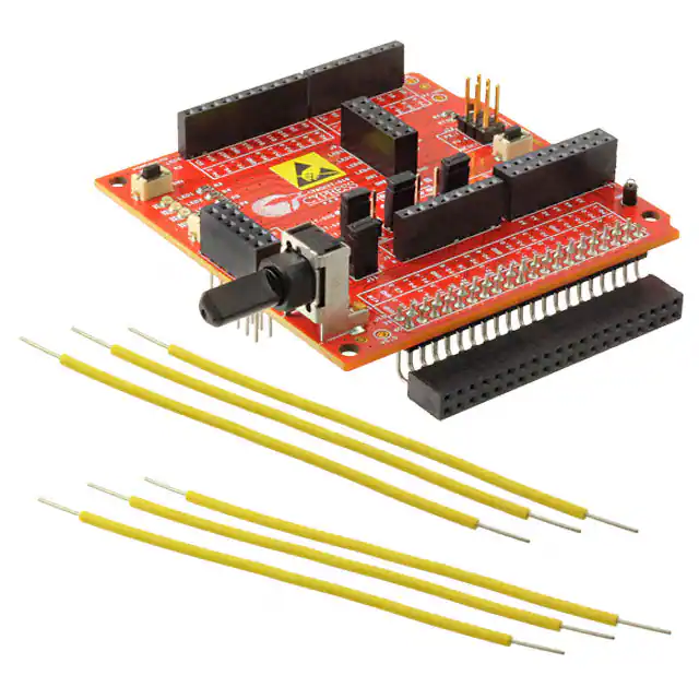
The PSoC Shield Adapter Kit contains the following:
■
PSoC Shield Adapter board (Figure 1-1)
■
Quick Start Guide
■
6 jumper wires
Inspect the content of your kit. If any part is missing, then contact your nearest Cypress sales office.
For further information, go to www.cypress.com/go/support.
Figure 1-1. PSoC Shield Adapter Board
CY8CKIT-019 PSoC Shield Adapter Kit Guide, Doc. #: 001-90332 Rev. **
4
�Introduction
1.2
Getting Started
This user guide helps you get acquainted with the PSoC Shield Adapter Kit. The Software
Installation chapter on page 6 describes the installation of the PSoC 4 Pioneer Kit software. The Kit
Operation chapter on page 11 explains how to program the PSoC 4 Pioneer Kit and use the PSoC
Shield Adapter. The Hardware chapter on page 15 details the hardware operation of the kit. Finally,
the Appendix on page 23 provides the kit schematics and the bill of materials (BOM).
1.3
Additional Learning Resources
For more information on PSoC, see the following links:
1.4
■
www.cypress.com/psoc
■
www.cypress.com/psoc4
■
www.cypress.com/psoccreator
■
www.cypress.com/go/CY8CKIT-042
■
www.cypress.com/go/CY8CKIT-025
■
www.cypress.com/go/CY8CKIT-031
■
www.cypress.com/go/CY8CKIT-036
Technical Support
For assistance, go to our support web page: http://www.cypress.com/go/support or contact our customer support at +1(800) 541-4736 Ext. 8 (in the U.S.), or +1 (408) 943-2600 Ext. 8 (International).
1.5
Document Conventions
Table 1-1. Document Conventions for Guides
Convention
Usage
Courier New
Displays file locations, user entered text, and source code:
C:\ ...cd\icc\
Italics
Displays file names and reference documentation:
Read about the sourcefile.hex file in the PSoC Creator User Guide.
[Bracketed, Bold]
Displays keyboard commands in procedures:
[Enter] or [Ctrl] [C]
File > Open
Represents menu paths:
File > Open > New Project
Bold
Displays commands, menu paths, and icon names in procedures:
Click the File icon and then click Open.
Times New Roman
Displays an equation:
2+2=4
Text in gray boxes
Describes Cautions or unique functionality of the product.
CY8CKIT-019 PSoC Shield Adapter Kit Guide, Doc. #: 001-90332 Rev. **
5
�2.
2.1
Software Installation
Kit Software
The PSoC Shield Adapter Kit does not require an installer, but it is recommended that you install the
PSoC 4 Pioneer Kit Installer.
The PSoC 4 Pioneer Kit Installer includes the PSoC Creator™ software and all of the kit related content. Navigate to the PSoC 4 Pioneer Kit web page and download the installer. You can then run the
downloaded installer. To install the PSoC 4 Pioneer Kit, follow these steps:
1. Run the installer and select the folder to install the CY8CKIT-042 PSoC 4 Pioneer Kit related files.
Choose the directory and click Next, as shown in Figure 2-1.
Figure 2-1. Initiating Pioneer Kit Installation
2. Select the Installation type and click Next, as shown in Figure 2-2.
CY8CKIT-019 PSoC Shield Adapter Kit Guide, Doc. #: 001-90332 Rev. **
6
�Software Installation
Figure 2-2. Selecting Installation Type
3. After the installation is complete, the kit contents are available at the following locations:
\CY8CKIT-042 PSoC 4 Pioneer Kit\
\PSoC Creator\
The default install directory is C:\Program Files\Cypress\
You can download the code examples for this kit from www.cypress.com/go/CY8CKIT-019.
The PSoC Shield Adapter also supports Expansion Board Kits (EBK). The following is a list of the
kits that the PSoC Shield Adapter supports. Navigate to the kit pages for additional installers, information, and content. Each kit page provides links to download the installers, application notes, and
example projects that use the CY8CKIT-019 PSoC Shield Adapter Kit.
CY8CKIT-025 - PSoC Precision Analog Temperature Sensor Expansion Board Kit
CY8CKIT-019 PSoC Shield Adapter Kit Guide, Doc. #: 001-90332 Rev. **
7
�Software Installation
CY8CKIT-031 - PSoC CapSense Expansion Board Kit
CY8CKIT-036 - PSoC Thermal Management Expansion Board Kit
2.2
Install Hardware
There is no additional hardware installation required for this kit.
2.3
Uninstall Software
The software and kit installers can be uninstalled using one of the following methods:
■
Go to Start > All Programs > Cypress > Cypress Update Manager > Cypress Update Manager; click the Uninstall button.
■
Go to Start > Control Panel > Programs and Features; click the Uninstall/Change button.
CY8CKIT-019 PSoC Shield Adapter Kit Guide, Doc. #: 001-90332 Rev. **
8
�Software Installation
2.4
Open a Code Example Project in PSoC Creator
1. Launch PSoC Creator software (Figure 2-3) from the Start menu. The path is Start > All Programs > Cypress > PSoC Creator x.x > PSoC Creator x.x, where "x.x" is the PSoC Creator
version.
Figure 2-3. PSoC Creator
2. Open the example projects by selecting File > Open > Project/Workspace and then navigating
to the example project that was downloaded from the kit web page.
Figure 2-4. Opening Example Projects
The example project opens and displays the project files in the Workspace Explorer, as shown in
Figure 2-5. Subsequent sections of this user guide show how to program and verify the output of the
example project supported by this kit.
CY8CKIT-019 PSoC Shield Adapter Kit Guide, Doc. #: 001-90332 Rev. **
9
�Software Installation
Figure 2-5. Project Files in Workspace Explorer
CY8CKIT-019 PSoC Shield Adapter Kit Guide, Doc. #: 001-90332 Rev. **
10
�3.
Kit Operation
The PSoC Shield Adapter Kit enables you to develop applications using the PSoC 4 Pioneer Kit and
Cypress EBKs. Figure 3-1 shows an image of the kit with references to the onboard components.
Figure 3-1. PSoC Shield Adapter Kit Components
CY8CKIT-019 PSoC Shield Adapter Kit Guide, Doc. #: 001-90332 Rev. **
11
�Kit Operation
3.1
Connecting the Shield Adapter Kit to the PSoC 4 Pioneer Kit
To use the PSoC Shield Adapter Kit, you need to connect the shield to the PSoC 4 Pioneer Kit. The
PSoC Shield Adapter Kit is designed to be connected to the entire header network on the PSoC 4
Pioneer Kit. You can key the headers and insert the shield into the PSoC 4 Pioneer Kit.
Figure 3-2. CY8CKIT-019 Shield Adapter Kit Connected to CY8CKIT-042 PSoC 4 Pioneer Kit
After the PSoC Shield Adapter is connected to the PSoC 4 Pioneer Kit, you can develop custom
applications, plug in new Arduino shields, or connect one of the Cypress EBKs to the shield's EBK
adapter.
3.2
Loading the First PSoC Shield Adapter Project
Available on the PSoC Shield Adapter Kit web page is an example project for the PSoC 4 Pioneer
Kit. This example project can be programmed onto the PSoC 4 device to blink an LED on the PSoC
Shield Adapter board. To verify this project, do the following:
1. Download and install the PSoC 4 Pioneer Kit Installer, as described in the Software Installation on
page 6.
2. Download the example project from the kit web page at www.cypress.com/go/CY8CKIT-019.
3. Unzip the example project to the desired location.
4. Connect the USB cable from the PC to the CY8CKIT-042 PSoC 4 Pioneer Kit.
5. Connect a jumper wire from the PSoC Shield Adapter prototyping header (LED1) on J9 to P0.4
(on J4), as shown in Figure 3-3.
CY8CKIT-019 PSoC Shield Adapter Kit Guide, Doc. #: 001-90332 Rev. **
12
�Kit Operation
Figure 3-3. Connecting a Jumper Wire
6. Launch PSoC Programmer (Figure 3-4) from Start > All Programs > Cypress > PSoC Programmer x.x.x > PSoC Programmer x.x.x, where x.x.x is the version. Using the File Load button on PSoC Programmer, navigate to the example project you have unzipped and select the
Blinking LED.hex file. This file is located under the Hex File sub-directory.
7. If the Status bar on the lower right corner of the PSoC Programmer window does not say "Connected", click on the KitProg programmer in the Port Selection window to connect.
Figure 3-4. PSoC Programmer
CY8CKIT-019 PSoC Shield Adapter Kit Guide, Doc. #: 001-90332 Rev. **
13
�Kit Operation
8. Click the Program button on PSoC Programmer. After programming, you will see that LED1
blinks, as shown in Figure 3-5.
Figure 3-5. LED1 Blinking
For more examples and solutions, refer to the EBK web pages and their associated solution documents:
■
www.cypress.com/go/CY8CKIT-025
■
www.cypress.com/go/CY8CKIT-031
■
www.cypress.com/go/CY8CKIT-036
CY8CKIT-019 PSoC Shield Adapter Kit Guide, Doc. #: 001-90332 Rev. **
14
�4.
4.1
Hardware
Board Details
As shown in Figure 3-1, the PSoC Shield Adapter Kit consists of the following sections:
4.2
■
Power supply system
■
Arduino headers
■
PSoC 5LP header
■
Expansion board kit adapter headers
■
Expansion board kit selector jumpers
■
LEDs
■
Thermistor
■
Push buttons
■
Potentiometer
Theory of Operation
This section provides a block-level description of the PSoC Shield Adapter Kit, as illustrated in
Figure 4-1.
Figure 4-1. PSoC Shield Adapter Kit Block-Level Diagram
CY8CKIT-019 PSoC Shield Adapter Kit Guide, Doc. #: 001-90332 Rev. **
15
�Hardware
The PSoC Shield Adapter board primarily provides header support for the PSoC 4 Pioneer Kits and
their connection to Cypress Expansion Board Kits (EBKs). The PSoC Shield Adapter Kit supports
connecting Arduino compatible shields and Cypress EBK development kits.
The kit supports onboard functionality for development and evaluation of PSoC 4-based designs.
The PSoC Shield Adapter board incorporates LEDs, push buttons, a potentiometer, and a thermistor. These features can be connected to the prototyping connector on the Shield Adapter Kit.
The PSoC Shield Adapter Kit supports four user LEDs and a power LED. The user LEDs can be
connected to the prototyping connector. It also supports a reset push button for resetting the PSoC 4
device on the PSoC 4 Pioneer Kit.
The PSoC 5LP header is not connected to any header or component on the Shield Adapter Kit - it
only connects to the PSoC 5LP, which is included on the PSoC 4 Pioneer Kit. You can connect
jumper wires from the PSoC 5LP header to various headers to expand functionality and to communicate to the PSoC 5LP.
4.3
Functional Description
4.3.1
PSoC 4
The PSoC Shield Adapter Kit is used with the PSoC 4 Pioneer Kit, which supports the PSoC 4200
family of devices. These devices combine a microcontroller with programmable logic, high-performance analog-to-digital conversion, two opamps with Comparator mode, and commonly used fixedfunction peripherals. For more information, refer to the PSoC 4 web page and the PSoC 4200 Family
Datasheet.
4.3.2
Power Supply System
The PSoC Shield Adapter board is powered using the base PSoC 4 Pioneer Kit power configurations. The power supply system (Figure 4-2) on the PSoC 4 Pioneer Kit is versatile, allowing the
board to be powered from the following sources:
■
5 V from onboard USB programming header J10
■
5 V to 12 V from VIN on the Arduino header J1_01 and J11
■
3.3 V from the Arduino header J1_05
■
VTARG - power from the onboard 10-pin programming headers J6 or J7 via an external programmer such as the MiniProg3
Figure 4-2. Power Supply System for the CY8CKIT-042 PSoC 4 Pioneer Kit
I/O Header
5V
3.3 V
Vin
MOSFET‐based
Protection Ckt
PSoC 4
USB
LDO
USB
5V
J9
PSoC 5LP
PTC
ESD
Protection
P4 10-Pin
Debug
P5LP 10-Pin
Debug
CY8CKIT-019 PSoC Shield Adapter Kit Guide, Doc. #: 001-90332 Rev. **
P5LP I/O
Header
16
�Hardware
On the CY8CKIT-019 PSoC Shield Adapter Kit, a power jumper J11 is included to control the power
from the PSoC 4 Pioneer Kit to the CY8CKIT-019 Shield.
J11
2
1
Figure 4-3. Power Supply Jumper
H DR2
P4_V DD
SH_ VDD
R8
ZE RO
No Load
Power Jumper
4.3.3
Arduino Compatible Headers (J1, J2, J3, J4, and J12)
The kit includes four Arduino compatible headers that mirror the header pinouts and header names
on the PSoC 4 Pioneer Kit. The headers are J1, J2, J3, J4, and J12. You can develop applications to
interface with the PSoC 4 Pioneer Kit.
Figure 4-4. Arduino Headers for CY8CKIT-019: J1, J2, J3, J4, and J12
The pinout selections of the J1 to J4 and J12 Arduino headers (Figure 4-5) mirror the pinout descriptions on the PSoC 4 Pioneer Kit, allowing easy reference for existing PSoC 4 Pioneer Kit users.
CY8CKIT-019 PSoC Shield Adapter Kit Guide, Doc. #: 001-90332 Rev. **
17
�Hardware
Figure 4-5. Pinout Selections of J1-J4 and J12 Arduino Headers
J3
P4_0
P4_1
P1_7
VIN
P4_VDD
J1
V5.0
V3.3
/XRES
IOREF
1
2
3
4
5
6
7
8
P0_6
P3_1
P3_0
P3_4
P3_6
P2_6
10
9
8
7
6
5
4
3
2
1
J12
P3_1
P0_6
/XRES
10X1 RECP
8x1 RECP
1
2
3
4
5
6
7
8
9
10
11 12
13 14
15 16
17 18
9x2 RECP
2
4
6
P3_0
3x2 RECPT
J2
P2_0
P2_1
P2_2
P2_3
P2_4
P2_5
P0_0
P0_1
P1_0
1
3
5
P0_2
P0_3
P4_VDD
P1_5
P1_4
P1_3
P1_2
P1_1
J4
P0_4
P0_5
P0_7
P3_7
P0_0
P3_5
P1_0
P2_7
1
2
3
4
5
6
7
8
8x1 RECP
J12 Arduino ICSP compatible
header for SPI Interface
(J1-J4) Arduino Stackable Headers
4.3.4
PSoC 5LP Header (J8)
The PSoC Shield Adapter Kit supports connections to the PSoC 4 Pioneer Kit PSoC 5LP header,
illustrated in Figure 4-6. The shield brings the header connection from the PSoC 4 Pioneer Kit to the
top layer of the Shield Adapter board. This 12-pin header supports the advanced features available
using the PSoC 5LP available on the PSoC 4 Pioneer Kit.
Figure 4-6. J8 PSoC 5LP Header
P5LP_VDD
P5LP0_0
P5LP3_4
P5LP3_6
P5LP12_6
J8
1
3
5
7
9
11
2
4
6
8
10
12
P5LP1_2
P5LP0_1
P5LP3_5
P5LP3_7
P5LP12_7
P5LP3_0
6x2 RECPT
NOTE: The PSoC 5LP Pins on J8
only bring out the Pins from
the Pioneer Kit and they are
not connected anywhere else in
this board.
PSoC 5LP GPIO Extension Header
4.3.5
Expansion Board Kit Adapter Header (J10)
The PSoC Shield Adapter Kit includes a single 2x20 pin adapter header, which is compatible with the
EBKs. This header supports connecting a Cypress EBKs to the PSoC Shield Adapter board and
then interfacing the EBK to the PSoC 4 Pioneer Kit.
The PSoC Shield Adapter board supports the CY8CKIT-025, CY8CKIT-031, and CY8CKIT-036
EBKs. Figure 4-7 details the pinout selections of the 40-pin header.
CY8CKIT-019 PSoC Shield Adapter Kit Guide, Doc. #: 001-90332 Rev. **
18
�Hardware
Figure 4-7. Pinout Selections of 40-Pin Header
4.3.5.1
PSoC Expansion Board Kit Selection Jumpers (J5, J6, J7)
The PSoC Shield Adapter Kit enables you to connect the CY8CKIT-025, CY8CKIT-031, and
CY8CKIT-036 EBKs. When connecting the EBK boards to the PSoC Shield Adapter, you need to
ensure the proper jumper selections. The PSoC Shield Adapter board contains three jumpers that
when arranged in a specified configuration enables support for the respective EBK. Figure 4-8 provides details on the possible configurations. You can refer to the onboard silkscreen for the correct
jumper configuration. By default, the PSoC Shield Adapter enables the CY8CKIT-036 EBK selection.
Figure 4-8. Expansion Board Header Jumpers and Configurations
P2_1
Pin 22
P1_7
P2_4
Pin 25
P4_1
P2_5
Pin 26
P4_0
HDR3
J7
HDR3
����
J6
3
2
1
3
2
1
3
2
1
HDR3
�����
J5
CY8CKIT-019 PSoC Shield Adapter Kit Guide, Doc. #: 001-90332 Rev. **
�
19
�Hardware
4.3.6
Prototyping Connector (J9)
The PSoC Shield Adapter board supports a number of onboard features. These features are not by
default connected to any of the Arduino compatible headers or the 2×20 pin adapter header. All
onboard functionality is connected through the J9 prototyping header (Figure 4-9), which is located
in the center of the PSoC Shield Adapter board. You need to connect jumper wires from the J9
header to enable any of the onboard functionality such as the LEDs, switches, potentiometer, and
thermistor.
Figure 4-9. J9 Prototyping Connector
4.3.7
Push Buttons
The kit has three push buttons: two user buttons and one reset button. The two user push buttons
(Figure 4-10) are available via the J9 prototyping connector. They are active pull-down buttons. To
use these two buttons, you need to make a connection between J9 and the target input pin.
Figure 4-10. User Push Buttons
SW1
SW1
1
2
EVQ-PE105K
SW2
SW2
1
2
EVQ-PE105K
The reset push button (Figure 4-11) is connected to the XRES pin of the PSoC 4 device through the
shield header and is used to reset the PSoC 4 device on the PSoC 4 Pioneer Kit.
CY8CKIT-019 PSoC Shield Adapter Kit Guide, Doc. #: 001-90332 Rev. **
20
�Hardware
Figure 4-11. Reset Push Button
SW3 RESET
/XRES
1
2
EVQ-PE105K
Push Buttons
4.3.8
User LEDs
The PSoC Shield Adapter Kit supports four blue LEDs (Figure 4-12), all connected to the J9 prototyping connector. To use these LEDs, you need to make a connection between J9 and the target output pin.
Figure 4-12. Blue LEDs
LED 1
R3
560 ohm
LED 2
R4
560 ohm
LED 3
R5
560 ohm
LED 4
R6
560 ohm
4.3.9
LED1
LED
LED2
LED
LED3
LED
LED4
LED
10K-Ohm Rotary Potentiometer
The PSoC Shield Adapter board includes a 10K-ohm rotary potentiometer (Figure 4-13) to provide
manual variable voltage values. This potentiometer is labeled R1. The potentiometer connection is
available on the J9 prototyping connector, so you need to wire your design to that connector to read
the voltage that is output from the potentiometer. The potentiometer receives its power via J11 and
will not draw any current if J11 is not connected. This is important if current measurement is needed
on the PSoC 4.
CY8CKIT-019 PSoC Shield Adapter Kit Guide, Doc. #: 001-90332 Rev. **
21
�Hardware
Figure 4-13. Rotary Potentiometer
POT
+
SH_VDD
C1
10uF
R1 POT 10K
Potentiometer
4.3.10
Thermistor
The PSoC Shield Adapter Kit supports an onboard thermistor (Figure 4-14) for measuring ambient
board temperature. The thermistor used on this kit is the NCP18XH103F03RB (NTC) device, which
has a 1 percent tolerance (10K ±1 percent) at 25 °C. The resistance of the thermistor changes with
temperature in a nonlinear fashion. Its output is connected to the prototyping connector and can be
used as an onboard temperature sensor. The thermistor receives its power via J11 and will not draw
any current if J11 is not connected. This is important if current measurement is needed on the
PSoC 4.
Figure 4-14. Thermistor
SH_VDD
VDD_REF
R7
10K ohm
VTHERM
t
RT1
Thermistor
NCP18XH103F03RB
GND_REF
Thermistor
CY8CKIT-019 PSoC Shield Adapter Kit Guide, Doc. #: 001-90332 Rev. **
22
�A.
A.1
Appendix
PSoC Shield Adapter Kit Schematics
P4_VDD
VIN
P4_0
P4_1
P1_7
J1
1
2
3
4
5
6
7
8
V5.0
V3.3
/XRES
IOREF
P0_6
P3_1
P3_0
P3_4
P3_6
P2_6
P2_0
P2_1
P2_2
P2_3
P2_4
P2_5
P0_0
P0_1
P1_0
1
3
5
7
9
11
13
15
17
P0_2
P0_3
2
4
6
8
10
12
14
16
18
10
9
8
7
6
5
4
3
2
1
10X1 RECP
8x1 RECP
J2
J3
P4_VDD
P1_5
P1_4
P1_3
P1_2
P1_1
J4
P0_4
P0_5
P0_7
P3_7
P0_0
P3_5
P1_0
P2_7
9x2 RECP
1
2
3
4
5
6
7
8
8x1 RECP
(J1-J4) Arduino Stackable Headers
P3_1
P0_6
/XRES
J12
1
3
5
2
4
6
P3_0
3x2 RECPT
J12 Arduino ICSP compatible
header for SPI Interface
P5LP_VDD
P5LP0_0
P5LP3_4
P5LP3_6
P5LP12_6
J8
1
3
5
7
9
11
2
4
6
8
10
12
P5LP1_2
P5LP0_1
P5LP3_5
P5LP3_7
P5LP12_7
P5LP3_0
6x2 RECPT
NOTE: The PSoC 5LP Pins on J8
only bring out the Pins from
the Pioneer Kit and they are
not connected anywhere else in
this board.
PSoC 5LP GPIO Extension Header
CY8CKIT-019 PSoC Shield Adapter Kit Guide, Doc. #: 001-90332 Rev. **
23
�LED 1
LED 2
LED 3
LED 4
SW1
SW2
P4_VDD
J9
1
3
5
7
9
11
2
4
6
8
10
12
VDD_REF
VTHERM
GND_REF
POT
6x2 RECPT
12 Pin Prototyping Header
POT
SH_VDD
+
C1
10uF
R1 POT 10K
Potentiometer
SW1
SW1
1
2
EVQ-PE105K
SW2
SW2
1
2
EVQ-PE105K
SW3
/XRES
1
RESET
2
EVQ-PE105K
Push Buttons
CY8CKIT-019 PSoC Shield Adapter Kit Guide, Doc. #: 001-90332 Rev. **
24
�J7
J5
1
2
3
1
2
3
HDR3
P2_1
Pin 22
P1_7
HDR3
P2_4
Pin 25
P4_1
P2_5
Pin 26
P4_0
1
2
3
J6
HDR3
3 Pin Jumpers
J5
1 2 3
Don't Care
J6
J7
1 2 3
1 2 3
CY8CKIT-025 Jumper Settings
J5
J6
J7
1 2 3
1 2 3
1 2 3
CY8CKIT-031 Jumper Settings
J5
J6
J7
1 2 3
1 2 3
1 2 3
CY8CKIT-036 Jumper Settings
Jumper Settings for
different EBKs
V5.0
V3.3
TP1
RED
NO LOAD
TP2
RED
NO LOAD
P4_VDD
TP3
RED
NO LOAD
NO LOAD
TP4
BLACK
GND
TP5
BLACK
GND
Test Points
CY8CKIT-019 PSoC Shield Adapter Kit Guide, Doc. #: 001-90332 Rev. **
25
�2
1
J11
HDR2
P4_VDD
R8
SH_VDD
ZERO
No Load
Power Jumper
SH_VDD
LED5
R2
560 ohm
LED1
R3
LED 1
560 ohm
560 ohm
560 ohm
LED
LED4
R6
LED 4
LED
LED3
R5
LED 3
LED
LED2
R4
LED 2
LED
560 ohm
LED
LEDs
SH_VDD
VDD_REF
R7
10K ohm
VTHERM
t
RT1
Thermistor
NCP18XH103F03RB
GND_REF
Thermistor
CY8CKIT-019 PSoC Shield Adapter Kit Guide, Doc. #: 001-90332 Rev. **
26
�P0_1
P0_0
P3_7
P3_5
GND
P0_4
P1_3
P3_1
P2_0
GND
P0_6
P2_2
Pin 25
P2_6
GND
P1_4
P4_1
V3.3
GND
VIN
1
3
5
7
9
11
13
15
17
19
21
23
25
27
29
31
33
35
37
39
J10
1
3
5
7
9
11
13
15
17
19
21
23
25
27
29
31
33
35
37
39
2
4
6
8
10
12
14
16
18
20
22
24
26
28
30
32
34
36
38
40
2
4
6
8
10
12
14
16
18
20
22
24
26
28
30
32
34
36
38
40
P1_1
P1_0
P3_6
P3_4
P0_5
P1_2
P3_0
P2_1
Pin 22
P2_3
Pin 26
P2_7
P1_5
P4_0
V5.0
GND
CON40
EBK Expansion Connector
A.2
Bill of Materials
Item
Qty
Reference
Value
Description
Manufacturer
Mfr Part Number
1
1
N/A
N/A
PCB, 71.12mm X 72.39mm, 2 Layer,
Enig Finish, High Tg, Color = RED
Cypress Semiconductor
600-60182-01
2
1
C1
10uF, 10V
CAP TANT 10UF 10V 20% 0805
AVX Corporation
TAJP106M010RN
J
3
2
J1,J4
8X1 RECP (Stackable)
8 POS Arduino Stackable Header
Samtec
SSQ-108-03-T-S
4
1
J2
9X2 RECP (Stackable)
18 POS Dual Row Stackable Header
Samtec
SSQ-109-03-T-D
5
1
J3
10X1 RECP (Stackable)
10 POS Arduino Stackable Header
Samtec
SSQ-110-03-T-S
3M
961103-6404-AR
6
3
J5,J6,J7
3 Pin Jumper
CONN HEADER VERT SGL 3POS
GOLD
7
1
J8
6X2 RECP (Stackable)
12 POS Dual Row Stackable Header
Samtec
SSQ-106-03-T-D
8
1
J9
6x2 RECP
CONN HEADER FMAL 12PS.1" DL
GOLD
Sullins Connector Solutions
PPPC062LFBNRC
9
1
J10
40X1 RECP
40 POS Dual Row R/A Connector
Samtec
ASP?178736?01
(Customized)
10
1
J11
2 Pin Jumper
CONN HEADER VERT SGL 2POS
GOLD
3M
961102-6404-AR
11
1
J12
3X2 RECP
CONN HEADER .100 DUAL STR
6POS
Sullins Connector Solutions
PBC03DFAN
12
3
SW1,SW2,SW3
Push Button
SWITCH TACTILE SPST-NO 0.05A
12V
Panasonic
EVQ-PE105K
13
1
RT1
Thermistor
THERMISTOR 10K OHM NTC 0603
SMD
Murata
NCP18XH103F03
RB
14
1
R1
POT 10K
POT 10K OHM 9MM HORZ PLA
SLEEVE
Panasonic
EVU-E3KFK4B14
CY8CKIT-019 PSoC Shield Adapter Kit Guide, Doc. #: 001-90332 Rev. **
27
�Item
Qty
15
5
16
Reference
Value
Description
Manufacturer
Mfr Part Number
R2,R3,R4,R5,R6
560 ohm
RES 560 OHM 1/8W 5% 0805 SMD
Panasonic
ERJ-6GEYJ561V
1
R7
10K Ohm
RES 10K OHM 1/10W 5% 0603 SMD Panasonic
ERJ-3GEYJ103V
17
4
LED1,LED2,LED
3,LED4
Blue LEDs
LED BLUE CLEAR 0805 SMD
Lite-On Inc
LTST-C170TBKT
18
1
LED5
Power LED (Amber)
LED AMBER 591NM DIFF LENS
2012
Avago
HSMA-C170
19
1
TP5
GND Test Point (Black)
TEST POINT PC MINI .040"D Black
Keystone Electronics
5001
No Load Components
20
3
TP1,TP2,TP3
RED
TEST POINT PC MINI .040"D RED
Keystone Electronics
5000
21
1
TP4
BLACK
TEST POINT PC MINI .040"D Black
Keystone Electronics
5001
Special Jumper Installation Instructions
22
1
J5
Install jumper across pins
1 and 2
MINI JUMPER GF 6.0MM CLOSE
TYPE BLACK
Kobiconn
151-8010-E
23
1
J6
Install jumper across pins
2 and 3
MINI JUMPER GF 6.0MM CLOSE
TYPE BLACK
Kobiconn
151-8010-E
24
1
J7
Install jumper across pins
2 and 3
MINI JUMPER GF 6.0MM CLOSE
TYPE BLACK
Kobiconn
151-8010-E
25
1
J11
Install jumper across pins
1 and 2
MINI JUMPER GF 6.0MM CLOSE
TYPE BLACK
Kobiconn
151-8010-E
26
1
N/A
N/A
LBL, PCA Label, Vendor Code, Datecode, Serial Number 121-60144-01
REV 01 (YYWWVVXXXXX)
Cypress Semiconductor
-
27
1
N/A
N/A
LBL, PCBA Anti-Static Warning,
10mm X 10mm
Cypress Semiconductor
-
Label
CY8CKIT-019 PSoC Shield Adapter Kit Guide, Doc. #: 001-90332 Rev. **
28
�Revision History
CY8CKIT-019 PSoC Shield Adapter Kit Guide Revision History
Document Title: CY8CKIT-019 PSoC® Shield Adapter Kit Guide
Document Number: 001-90332
Revision
**
Issue Date
12/11/2013
Origin of
Change
VRNK
Description of Change
New kit guide
CY8CKIT-019 PSoC Shield Adapter Kit Guide, Doc. #: 001-90332 Rev. **
29
�