S79FL256S/S79FL512S
256 Mbit (32 MB)/512 Mbit (64 MB),
3 V, Dual-Quad SPI Flash
Features
Density
– 256 Mbit (32 Mbytes)
– 512 Mbit (64 Mbytes)
Serial Peripheral Interface (SPI)
– SPI Clock polarity and phase modes 0 and 3
– Double Data Rate (DDR) option
– Extended Addressing: 24- or 32-bit address options
READ Commands
– Dual-Quad SPI Quad Read: 104 MHz clock rate (104 MB/
s)
– Dual-Quad SPI Quad DDR Read: 80 MHz clock rate (160
MB/s)
– Normal, Fast, Quad, Quad DDR
– AutoBoot - power up or reset and execute a Normal or
Quad read command automatically at a preselected
address
– Common Flash Interface (CFI) data for configuration
information.
Programming (3 Mbytes/s)
– 512-byte or 1024-byte Page Programming buffer options
– Quad-Input Page Programming (QPP) for slow clock
systems
– Automatic ECC - internal hardware Error Correction Code
generation with single bit error correction
Erase (1 Mbyte/s)
– Hybrid sector size option – physical set of thirty two 8-kbyte
sectors at top or bottom of address space with all
remaining sectors of
128 kbytes
– Uniform sector option – always erase 512-kbyte blocks for
software compatibility with higher density and future
devices.
Cycling Endurance
– 100,000 Program-Erase Cycles on any sector, minimum
Cypress Semiconductor Corporation
Document Number: 002-00518 Rev. *D
•
Data Retention
– 20 Year Data Retention, minimum
Security features
– Separate One Time Program (OTP) array of 2048 bytes
– Block Protection:
– Status Register bits to control protection against
program or erase of a contiguous range of sectors.
– Hardware and software control options
– Advanced Sector Protection (ASP)
– Individual sector protection controlled by boot code or
password
Cypress® 65 nm MirrorBit® Technology with Eclipse™
Architecture
Core Supply Voltage: 2.7V to 3.6V
Temperature Range:
– Industrial (-40°C to +85°C)
– Industrial Plus (-40°C to +105°C)
– Automotive, AEC-Q100 Grade 3 (-40°C to +85°C)
– Automotive, AEC-Q100 Grade 2 (-40°C to +105°C)
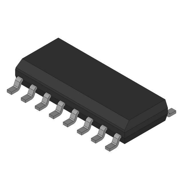
Packages (all Pb-free)
– 16-lead SOIC (300 mil)
Software Features
– Program Suspend and Resume
– Erase Suspend and Resume
– Status Register provides status of embedded erase or
programming operation
– Common Flash Interface (CFI) Compliant — allows host
system to identify the flash device and determine its
capabilities
– User-configurable Configuration Register
Hardware Features
– Hardware Reset input (RESET#) - resets device to standby
state
198 Champion Court
•
San Jose, CA 95134-1709
•
408-943-2600
Revised November 09, 2017
�S79FL256S/S79FL512S
Performance Summary
Maximum Read Rates SDR Dual-Quad SPI
Clock Rate
(MHz)
Mbytes/s
Read
50
12.5
Fast Read
133
33
Quad Read
104
104
Clock Rate
(MHz)
Mbytes/s
80
160
Command
Maximum Read Rates DDR Dual-Quad SPI
Command
DDR Quad Read
Typical Program and Erase Rates Dual-Quad SPI
Operation
kbytes/s
Page Programming (512-byte page buffer)
2000
Page Programming (1024-byte page buffer)
3000
8-kbyte Physical Sector Erase (Hybrid Sector Option)
60
128-kbyte Physical Sector Erase (Hybrid Sector Option)
1000
512-kbyte Logical Sector Erase
1000
Typical Current Consumption, Dual-Quad SPI
Operation
Current (mA)
Serial Read 50 MHz
32 (max)
Serial Fast Read 133 MHz
66 (max)
Quad Read 104 MHz
122 (max)
Program
200 (max)
Erase
200 (max)
Standby
0.14 (typ)
Document Number: 002-00518 Rev. *D
Page 2 of 111
�S79FL256S/S79FL512S
Contents
1.
1.1
1.2
1.3
Overview .......................................................................
General Description .......................................................
Glossary.........................................................................
Other Resources............................................................
4
4
4
5
Hardware Interface
2.
2.1
2.2
2.3
2.4
2.5
2.6
2.7
2.8
2.9
2.10
2.11
2.12
2.13
2.14
Signal Descriptions .....................................................
Input/Output Summary...................................................
Multiple Input / Output (Dual-Quad SPI) ........................
RESET# .........................................................................
Multiple Input / Output (Dual-Quad) ...............................
Serial Clock (SCK) .........................................................
Chip Select (CS#) ..........................................................
Input Output IO0 - IO7 ...................................................
Core Voltage Supply (VCC) ............................................
Versatile I/O Power Supply (VIO) ...................................
Supply and Signal Ground (VSS) ...................................
Not Connected (NC) ......................................................
Reserved for Future Use (RFU).....................................
Do Not Use (DNU) .........................................................
Block Diagrams..............................................................
3.
3.1
3.2
3.3
3.4
3.5
Signal Protocols.........................................................
SPI Clock Modes .........................................................
Command Protocol ......................................................
Interface States............................................................
Configuration Register Effects on the Interface ...........
Data Protection ............................................................
10
10
11
15
18
18
4.
4.1
4.2
4.3
4.4
Electrical Specifications............................................
Absolute Maximum Ratings .........................................
Operating Ranges........................................................
Power-Up and Power-Down ........................................
DC Characteristics .......................................................
19
19
19
20
22
5.
5.1
5.2
5.3
5.4
5.5
Timing Specifications................................................
Key to Switching Waveforms .......................................
AC Test Conditions ......................................................
Reset............................................................................
SDR AC Characteristics...............................................
DDR AC Characteristics ..............................................
23
23
23
24
27
29
6.
6.1
6.2
Physical Interface ...................................................... 31
Dual-Quad SOIC 16-Lead Package............................. 31
SOIC 16 Physical Diagram .......................................... 32
Document Number: 002-00518 Rev. *D
6
6
7
7
7
7
8
8
8
8
8
8
8
8
9
Software Interface
7.
7.1
7.2
7.3
7.4
7.5
Address Space Maps.................................................. 33
Overview....................................................................... 33
Flash Memory Array...................................................... 33
ID-CFI Address Space .................................................. 35
OTP Address Space ..................................................... 35
Registers....................................................................... 37
8.
8.1
8.2
8.3
8.4
Data Protection ........................................................... 46
Secure Silicon Region (OTP)........................................ 46
Write Enable Command................................................ 46
Block Protection ............................................................ 47
Advanced Sector Protection ......................................... 48
9.
9.1
9.2
9.3
9.4
9.5
9.6
9.7
9.8
9.9
9.10
Commands .................................................................. 52
Command Set Summary............................................... 53
Identification Commands .............................................. 59
Register Access Commands......................................... 61
Read Memory Array Commands .................................. 70
Program Flash Array Commands ................................. 77
Erase Flash Array Commands...................................... 81
One Time Program Array Commands .......................... 85
Advanced Sector Protection Commands ...................... 86
Reset Commands ......................................................... 92
Embedded Algorithm Performance Tables ................... 93
10. Data Integrity ............................................................... 94
10.1 Erase Endurance .......................................................... 94
10.2 Data Retention .............................................................. 94
11. Software Interface Reference .................................... 95
11.1 Command Summary ..................................................... 95
11.2 Device ID and Common Flash Interface
(ID-CFI) Address Map................................................... 97
11.3 Initial Delivery State .................................................... 107
Ordering Information
12.
Ordering Information S79FL256S/S79FL512S........ 108
13. Revision History........................................................ 110
Document History Page ....................................................110
Sales, Solutions, and Legal Information .........................111
Worldwide Sales and Design Support ..........................111
Products .......................................................................111
PSoC® Solutions .........................................................111
Cypress Developer Community ....................................111
Technical Support ........................................................111
Page 3 of 111
�S79FL256S/S79FL512S
1. Overview
1.1
General Description
The Cypress S79FL256S/S79FL512S devices are flash non-volatile memory products using:
MirrorBit technology - that stores two data bits in each memory array transistor
Eclipse architecture - that dramatically improves program and erase performance
65 nm process lithography
The S79FL256S/S79FL512S devices connect two Quad I/O SPI devices with a single CS# resulting in an eight bit I/O data path.
This Byte I/O interface is called Dual-Quad I/O.
These devices connect to a host system via a Serial Peripheral Interface (SPI). Traditional SPI single bit serial input and output (IO1
and IO5) is supported as well as four-bit (Quad I/O or QIO) serial commands. This multiple width interface is called SPI Multi-I/O or
MIO. In addition, these two devices add support for Double Data Rate (DDR) read commands for QIO that transfers address and
read data on both edges of the clock.
The Eclipse architecture features a Page Programming Buffer that allows up to 256 words (512 bytes) or 512 words (1024 bytes) to
be programmed in one operation, resulting in significantly faster effective programming (up to 2 MB/s or 3 MB/s respectively) and
erase (up to 1 MB/s) than prior generation SPI program or erase algorithms.
Executing code directly from flash memory is often called Execute-In-Place or XIP. By using the S79FL-S devices at the higher clock
rates supported, with QIO or DDR-QIO commands, the instruction read transfer rate can match or exceed traditional parallel
interface, asynchronous, NOR flash memories while reducing signal count dramatically.
The S79FL-S products offer high density coupled with the fastest read and write performance required by a variety of embedded
applications. They are ideal for code shadowing, XIP, and data storage.
1.2
Glossary
Command
All information transferred between the host system and memory during one period while CS# is low.
This includes the instruction (sometimes called an operation code or opcode) and any required
address, mode bits, latency cycles, or data.
DDP
(Dual Die Package)
Two die stacked within the same package to increase the memory capacity of a single package.
Often also referred to as a Multi-Chip Package (MCP).
DDR
(Double Data Rate)
When input and output are latched on every edge of SCK.
ECC
ECC Unit = 16 byte aligned and length data groups in the main Flash array and OTP array, each of
which has its own hidden ECC syndrome to enable error correction on each group.
Flash
The name for a type of Electrical Erase Programmable Read Only Memory (EEPROM) that erases
large blocks of memory bits in parallel, making the erase operation much faster than early EEPROM.
High
A signal voltage level ≥ VIH or a logic level representing a binary one (1).
Instruction
The 8 bit code indicating the function to be performed by a command (sometimes called an
operation code or opcode). The instruction is always the first 8 bits transferred from host system to
the memory in any command.
Low
A signal voltage level VIL or a logic level representing a binary zero (0).
LSB
(Least Significant Bit)
Generally the right most bit, with the lowest order of magnitude value, within a group of bits of a
register or data value.
MSB
(Most Significant Bit)
Generally the left most bit, with the highest order of magnitude value, within a group of bits of a
register or data value.
Non-Volatile
No power is needed to maintain data stored in the memory.
Document Number: 002-00518 Rev. *D
Page 4 of 111
�S79FL256S/S79FL512S
OPN
(Ordering Part Number)
The alphanumeric string specifying the memory device type, density, package, factory non-volatile
configuration, etc. used to select the desired device.
Page
512 or 1024 bytes aligned and length group of data.
PCB
Printed Circuit Board.
Register Bit References
Are in the format: Register_name[bit_number] or Register_name[bit_range_MSB: bit_range_LSB].
SDR
(Single Data Rate)
When input is latched on the rising edge and output on the falling edge of SCK.
Sector
Erase unit size; depending on device model and sector location, this may be 8 kbytes,
128 kbytes or 512 kbytes.
Write
An operation that changes data within volatile or non-volatile registers bits or non-volatile flash
memory. When changing non-volatile data, an erase and reprogramming of any unchanged nonvolatile data is done, as part of the operation, such that the non-volatile data is modified by the write
operation, in the same way that volatile data is modified – as a single operation. The non-volatile
data appears to the host system to be updated by the single write command, without the need for
separate commands for erase and reprogram of adjacent, but unaffected data.
1.3
1.3.1
Other Resources
Cypress Flash Memory Roadmap
www.cypress.com/product-roadmaps/cypress-flash-memory-roadmap
1.3.2
Links to Software
www.cypress.com/software-and-drivers-cypress-flash-memory
1.3.3
Links to Application Notes
www.cypress.com/appnotes
1.3.4
Specification Bulletins
Specification bulletins provide information on temporary differences in feature description or parametric variance since the
publication of the last full data sheet. Contact your local sales office for details. Obtain the latest list of company locations and
contact information at www.cypress.com/contact-us.
Document Number: 002-00518 Rev. *D
Page 5 of 111
�S79FL256S/S79FL512S
Hardware Interface
Serial Peripheral Interface with Multiple Input / Output (SPI-MIO) Dual-Quad
Many memory devices connect to their host system with separate parallel control, address, and data signals that require a large
number of signal connections and larger package size. The large number of connections increase power consumption due to so
many signals switching and the larger package increases cost.
The S25FL-S Dual-Quad SPI devices reduce the number of signals for connection to the host system by serially transferring all
control, address, and data information over 10 signals. This reduces the cost of the memory package, reduces signal switching
power, and either reduces the host connection count or frees host connectors for use in providing other features.
The S25FL-S Dual-Quad SPI devices use the industry standard single bit Serial Peripheral Interface (SPI) using two Quad SPI
devices in each package (Quad SPI-1 and Quad SPI-2). This interface is called Dual-Quad and enables support of Byte wide (8 bit)
serial transfers. There is one package option available for S79FL256S/S79FL512S:
16-pin SOIC package
For documentation simplicity, all AC timings and waveforms and DC specification are defined using single CS# (Chip Select) and
SCK (Serial Clock) signals. For S79FL256S/S79FL512S, the CS# signals and the SCK signals for Quad SPI-1 and Quad SPI-2 are
internally tied together in the package.
2. Signal Descriptions
2.1
Input/Output Summary
Table 1. Dual-Quad Input/Output Descriptions
Signal Name
Type
Description
RESET#
Input
Hardware Reset: Low = device resets and returns to standby state, ready to receive a
command. The signal has an internal pull-up resistor and may be left unconnected in
the host system if not used.
SCK
Input
Serial Clock
CS#
Input
Chip Select
IO0
I/O
I/O 0 for Quad SPI-1
IO1
I/O
I/O 1 for Quad SPI-1
IO2
I/O
I/O 2 for Quad SPI-1
IO3
I/O
I/O 3 for Quad SPI-1
IO4
I/O
I/O 0 for Quad SPI-2
IO5
I/O
I/O 1 for Quad SPI-2
IO6
I/O
I/O 2 for Quad SPI-2
IO7
I/O
I/O 3 for Quad SPI-2
VCC
Supply
Core Power Supply
VSS
Supply
Ground
Unused
Not Connected. No device internal signal is connected to the package connector nor is
there any future plan to use the connector for a signal. The connection may safely be
used for routing space for a signal on a Printed Circuit Board (PCB). However, any
signal connected to a NC pin must not have voltage levels higher than the VCC
absolute maximum (Supply Voltage).
Reserved
Reserved for Future Use. No device internal signal is currently connected to the
package connector but there is potential future use for the connector for a signal. It is
recommended to not use RFU connectors for PCB routing channels so that the PCB
may take advantage of future enhanced features in compatible footprint devices.
NC
RFU
Document Number: 002-00518 Rev. *D
Page 6 of 111
�S79FL256S/S79FL512S
Table 1. Dual-Quad Input/Output Descriptions (Continued)
Signal Name
DNU
2.2
Type
Description
Reserved
Do Not Use. A device internal signal may be connected to the package connector. The
connection may be used by Cypress for test or other purposes and is not intended for
connection to any host system signal. Any DNU signal related function will be inactive
when the signal is at VIL. The signal has an internal pull-down resistor and may be left
unconnected in the host system or may be tied to VSS. Do not use these connections
for PCB signal routing channels. Do not connect any host system signal to this
connection.
Multiple Input / Output (Dual-Quad SPI)
Quad Input / Output (I/O) commands send instructions to the memory only on the IO0 (Quad SPI-1) and IO4 (Quad SPI-2) signals.
Address is sent from the host to the memory as four bit (nibble) on IO0, IO1, IO2, IO3 (Quad SPI-1)and repeated on IO4, IO5, IO6,
IO7 (Quad SPI-2). Data is sent and returned to the host as bytes on IO0 - IO7.
2.3
RESET#
The RESET# input provides a hardware method of resetting the device to standby state, ready for receiving a command. When
RESET# is driven to logic low (VIL) for at least a period of tRP, the device:
terminates any operation in progress,
tristates all outputs,
resets the volatile bits in the Configuration Register,
resets the volatile bits in the Status Registers,
resets the Bank Address Register to zero,
loads the Program Buffer with all ones,
reloads all internal configuration information necessary to bring the device to standby mode,
and resets the internal Control Unit to standby state.
RESET# causes the same initialization process as is performed when power comes up and requires tPU time.
RESET# may be asserted low at any time. To ensure data integrity any operation that was interrupted by a hardware reset should
be reinitiated once the device is ready to accept a command sequence.
When RESET# is first asserted Low, the device draws ICC1 (50 MHz value) during tPU. If RESET# continues to be held at VSS the
device draws CMOS standby current (ISB).
RESET# has an internal pull-up resistor and may be left unconnected in the host system if not used.
The RESET# input is not available on all packages options. When not available the RESET# input of the device is tied to the inactive
state, inside the package.
2.4
Multiple Input / Output (Dual-Quad)
Quad Input / Output (I/O) commands send instructions to the memory only on the IO0 (Quad SPI-1) and IO4 (Quad SPI-2) signals.
Address is sent from the host to the memory as four bit (nibble) on IO0, IO1, IO2, IO3 (Quad SPI-1)and repeated on IO4, IO5, IO6,
IO7 (Quad SPI-2). Data is sent and returned to the host as bytes on IO0 - IO7.
2.5
Serial Clock (SCK)
This input signal provides the synchronization reference for the SPI interface. Instructions, addresses, or data input are latched on
the rising edge of the SCK signal. Data output changes after the falling edge of SCK, in SDR commands, and after every edge in
DDR commands.
Document Number: 002-00518 Rev. *D
Page 7 of 111
�S79FL256S/S79FL512S
2.6
Chip Select (CS#)
The chip select signal indicates when a command for the device is in process and the other signals are relevant for the memory
device. When the CS# signal is at the logic high state, the device is not selected and all input signals are ignored and all output
signals are high impedance. Unless an internal Program, Erase or Write Registers (WRR) embedded operation is in progress, the
device will be in the Standby Power mode. Driving the CS# input to logic low state enables the device, placing it in the Active Power
mode. After Power-up, a falling edge on CS# is required prior to the start of any command.
2.7
Input Output IO0 - IO7
These signals are input and outputs for receiving instructions, addresses, and data to be programmed (values latched on rising edge
of serial SCK clock signal) as well as shifting out data (on the falling edge of SCK, in SDR commands, and on every edge of SCK, in
DDR commands).
2.8
Core Voltage Supply (VCC)
VCC is the voltage source for all device internal logic. It is the single voltage used for all device internal functions including read,
program, and erase. The voltage may vary from 2.7V to 3.6V.
2.9
Versatile I/O Power Supply (VIO)
VIO functionality is not supported on the standard configuration of the S79FL256S/S79FL512S devices.
2.10
Supply and Signal Ground (VSS)
VSS is the common voltage drain and ground reference for the device core, input signal receivers, and output drivers.
2.11
Not Connected (NC)
No device internal signal is connected to the package connector nor is there any future plan to use the connector for a signal. The
connection may safely be used for routing space for a signal on a Printed Circuit Board (PCB). However, any signal connected to an
NC must not have voltage levels higher than VCC.
2.12
Reserved for Future Use (RFU)
No device internal signal is currently connected to the package connector but is there potential future use of the connector. It is
recommended to not use RFU connectors for PCB routing channels so that the PCB may take advantage of future enhanced
features in compatible footprint devices.
2.13
Do Not Use (DNU)
A device internal signal may be connected to the package connector. The connection may be used by Cypress for test or other
purposes and is not intended for connection to any host system signal. Any DNU signal related function will be inactive when the
signal is at VIL. The signal has an internal pull-down resistor and may be left unconnected in the host system or may be tied to VSS.
Do not use these connections for PCB signal routing channels. Do not connect any host system signal to these connections.
Document Number: 002-00518 Rev. *D
Page 8 of 111
�S79FL256S/S79FL512S
2.14
Block Diagrams
Figure 1. SPI Host and S79FL256S / S79FL512S Dual-Quad SPI Devices in the 16-Pin SOIC Package
IO0 – IO3
SCK
CS#
RESET#
IO0 – IO3
SCK
CS#
RESET#
Quad SPI -1
Quad SPI -2
IO4 – IO7
SPI HOST
IO4 – IO7
S79FL256S / S79FL512S Dual-Quad Device
Note:
1. The Chip Select (CS#) and Clock (SCK) signals for Quad SPI-1 and Quad SPI-2 are internally tied together in the 16-pin SOIC package.
Document Number: 002-00518 Rev. *D
Page 9 of 111
�S79FL256S/S79FL512S
3.
3.1
3.1.1
Signal Protocols
SPI Clock Modes
Single Data Rate (SDR)
The S25FL-S devices can be driven by an embedded microcontroller (bus master) in either of the two following clocking modes.
Mode 0 with Clock Polarity (CPOL) = 0 and, Clock Phase (CPHA) = 0
Mode 3 with CPOL = 1 and, CPHA = 1
For these two modes, input data into the device is always latched in on the rising edge of the SCK signal and the output data is
always available from the falling edge of the SCK clock signal.
The difference between the two modes is the clock polarity when the bus master is in standby mode and not transferring any data.
SCK will stay at logic low state with CPOL = 0, CPHA = 0
SCK will stay at logic high state with CPOL = 1, CPHA = 1
Figure 2. Dual-Quad SPI SDR Modes Supported
CPOL=0_CPHA=0_SCLK
CPOL=1_CPHA=1_SCLK
CS#
IO0
MSB
IO1
IO4
MSB
MSB
IO5
MSB
Timing diagrams throughout the remainder of the document are generally shown as both mode 0 and 3 by showing SCK as both
high and low at the fall of CS#. In some cases a timing diagram may show only mode 0 with SCK low at the fall of CS#. In such a
case, mode 3 timing simply means clock is high at the fall of CS# so no SCK rising edge set up or hold time to the falling edge of
CS# is needed for mode 3.
SCK cycles are measured (counted) from one falling edge of SCK to the next falling edge of SCK. In mode 0 the beginning of the
first SCK cycle in a command is measured from the falling edge of CS# to the first falling edge of SCK because SCK is already low
at the beginning of a command.
3.1.2
Double Data Rate (DDR)
Mode 0 and Mode 3 are also supported for DDR commands. In DDR commands, the instruction bits are always latched on the rising
edge of clock, the same as in SDR commands. However, the address and input data that follow the instruction are latched on both
the rising and falling edges of SCK. The first address bit is latched on the first rising edge of SCK following the falling edge at the end
of the last instruction bit. The first bit of output data is driven on the falling edge at the end of the last access latency (dummy) cycle.
SCK cycles are measured (counted) in the same way as in SDR commands, from one falling edge of SCK to the next falling edge of
SCK. In mode 0 the beginning of the first SCK cycle in a command is measured from the falling edge of CS# to the first falling edge
of SCK because SCK is already low at the beginning of a command.
Document Number: 002-00518 Rev. *D
Page 10 of 111
�S79FL256S/S79FL512S
Figure 3. Dual-Quad SPI DDR Modes Supported
CPOL=0_CPHA=0_SCLK
CPOL=1_CPHA=1_SCLK
CS#
Instruction
Transfer_Phase
IO0
3.2
Dummy / DLP
A0 M4 M0
DLP.
DLP.
D0 D1
IO1
A29 A25
A1 M5 M1
DLP.
DLP.
D0 D1
IO2
A30 A26
A2 M6 M2
DLP.
DLP.
D0 D1
IO3
A31 A27
A3 M7 M3
DLP.
DLP.
D0 D1
A28 A24
A0 M4 M0
DLP.
DLP.
D0 D1
IO5
A29 A25
A1 M5 M1
DLP.
DLP.
D0 D1
IO6
A30 A26
A2 M6 M2
DLP.
DLP.
D0 D1
IO7
A31 A27
A3 M7 M3
DLP.
DLP.
D0 D1
Inst. 7
Inst. 0
Mode
A28 A24
IO4
Inst. 7
Address
Inst. 0
Command Protocol
All communication between the host system and S25FL-S memory devices is in the form of units called commands.
All commands begin with an instruction that selects the type of information transfer or device operation to be performed. Commands
may also have an address, instruction modifier, latency period, data transfer to the memory, or data transfer from the memory. All
instruction, address, and data information is transferred serially between the host system and memory device.
Quad Input / Output (I/O) commands provide an address sent from the host as four bit (nibble) groups on IO0, IO1, IO2, IO3 and
repeated on IO4, IO5, IO6, IO7, then followed by dummy cycles. Data is returned to the host as byte on IO0 - IO7. This is referenced
as 2-8-8 for Quad I/O command protocols.
Commands are structured as follows:
Each command begins with CS# going low and ends with CS# returning high. The memory device is selected by the host driving
the Chip Select (CS#) signal low throughout a command.
The serial clock (SCK) marks the transfer of each bit or group of bits between the host and memory.
Each command begins with an 8-bit (byte) instruction. The instruction is always presented only as a single bit serial sequence on
the Serial Input (SI) signal with one bit transferred to the memory device on each SCK rising edge. The instruction selects the type
of information transfer or device operation to be performed.
The instruction may be stand alone or may be followed by address bits to select a location within one of several address spaces
in the device. The instruction determines the address space used. The address may be either a 24-bit or a 32-bit byte boundary,
address. The address transfers occur on SCK rising edge, in SDR commands, or on every SCK edge, in DDR commands.
Quad I/O read instructions send an instruction modifier called Continuous Read mode bits, following the address, to indicate
whether the next command will be of the same type with an implied, rather than an explicit, instruction. These mode bits initiate or
end the continuous read mode. In continuous read mode, the next command thus does not provide an instruction byte, only a new
address and mode bits. This reduces the time needed to send each command when the same command type is repeated in a
sequence of commands. The mode bit transfers occur on SCK rising edge, in SDR commands, or on every SCK edge, in DDR
commands.
Document Number: 002-00518 Rev. *D
Page 11 of 111
�S79FL256S/S79FL512S
The width of all transfers following the instruction are determined by the instruction sent. Following transfers may continue to be
single bit serial on only the SI or Serial Output (SO) signals, they may be done in 4-bit groups per (quad) transfer on the IO0-IO3
signals. Within the quad groups the least significant bit is on IO0. More significant bits are placed in significance order on each
higher numbered IO signal. Single bits or parallel bit groups are transferred in most to least significant bit order.
Some instructions send an instruction modifier called mode bits, following the address, to indicate that the next command will be
of the same type with an implied, rather than an explicit, instruction. The next command thus does not provide an instruction byte,
only a new address and mode bits. This reduces the time needed to send each command when the same command type is
repeated in a sequence of commands. The mode bit transfers occur on SCK rising edge, in SDR commands, or on every SCK
edge, in DDR commands.
The address or mode bits may be followed by write data to be stored in the memory device or by a read latency period before
read data is returned to the host.
Write data bit transfers occur on SCK rising edge, in SDR commands, or on every SCK edge, in DDR commands.
SCK continues to toggle during any read access latency period. The latency may be zero to several SCK cycles (also referred to
as dummy cycles). At the end of the read latency cycles, the first read data bits are driven from the outputs on SCK falling edge at
the end of the last read latency cycle. The first read data bits are considered transferred to the host on the following SCK rising
edge. Each following transfer occurs on the next SCK rising edge, in SDR commands, or on every SCK edge, in DDR commands.
If the command returns read data to the host, the device continues sending data transfers until the host takes the CS# signal high.
The CS# signal can be driven high after any transfer in the read data sequence. This will terminate the command.
At the end of a command that does not return data, the host drives the CS# input high. The CS# signal must go high after the
eighth bit, of a stand alone instruction or, of the last write data byte that is transferred. That is, the CS# signal must be driven high
when the number of clock cycles after CS# signal was driven low is an exact multiple of eight cycles. If the CS# signal does not go
high exactly at the eight SCK cycle boundary of the instruction or write data, the command is rejected and not executed.
All instruction, address, and mode bits are shifted into the device with the Most Significant Bits (MSB) first. The data bits are
shifted in and out of the device MSB first. All data is transferred in byte units with the lowest address byte sent first. Following
bytes of data are sent in lowest to highest byte address order i.e. the byte address increments.
All attempts to read the flash memory array during a program, erase, or a write cycle (embedded operations) are ignored. The
embedded operation will continue to execute without any affect. A very limited set of commands are accepted during an
embedded operation. These are discussed in the individual command descriptions.
Depending on the command, the time for execution varies. A command to read status information from an executing command is
available to determine when the command completes execution and whether the command was successful.
3.2.1
Command Sequence Examples
Figure 4. Dual-Quad Stand Alone Instruction Command
CS#
SCK
IO0
7
6
5
4
3
2
1
0
7
6
5
4
3
2
1
0
IO1-IO3
IO4
IO5-IO7
Phase
Instruction
Note:
1. Instruction needs to be the same for both IO0 (Quad SPI-1) and IO4 (Quad SPI-2).
Document Number: 002-00518 Rev. *D
Page 12 of 111
�S79FL256S/S79FL512S
Figure 5. Dual-Quad Single Bit Wide Input Command
CS#
SCLK
IO0
7
6
5
4
3
2
1
0
7
6
5
4
3
2
1
0
IO4
7
6
5
4
3
2
1
0
7
6
5
4
3
2
1
0
Phase
Instruction
Input Data
Note:
1. Instruction needs to be the same for both IO0 (Quad SPI-1) and IO4 (Quad SPI-2).
Figure 6. Dual-Quad Single Bit Wide I/O Command without Latency
CS#
SCLK
IO0
7
6
5
4
3
2
1
0 31
1
0
IO1
3 2
1
0
3
2
1 0
IO2-IO3
IO4
7
6
5
4
3
2
1
0 31
1
0
IO5
7 6
5
4
7
6
5
4
IO6-IO7
Phase
Instruction
Address
Data 1
Data 2
Note:
1. Instruction needs to be the same for both IO0 (Quad SPI-1) and IO4 (Quad SPI-2).
Figure 7. Dual-Quad Single Bit Wide I/O Command with Latency
CS#
SCLK
IO0
7
6
5
4
3
2
1
0 31
1
0
IO1
3
2
1
0
3
2
1
0
7
6
5
4
7
6
5
4
IO2-IO3
IO4
7
6
5
4
3
2
1
0 31
1
0
IO5
IO6-IO7
Phase
Instruction
Address
Dummy Cycles
Data 1
Data 2
Note:
1. Instruction needs to be the same for both IO0 (Quad SPI-1) and IO4 (Quad SPI-2).
Document Number: 002-00518 Rev. *D
Page 13 of 111
�S79FL256S/S79FL512S
Figure 8. Dual-Quad, Quad Output Read Command
CS#
SCK
IO0
0
0
0
0
0
IO1
7
6
5
4
3
2
1
0
A
1
0
1
1
1
1
1
IO2
2
2
2
2
2
3
3
3
3
3
4
4
4
4
4
IO5
5
5
5
5
5
IO6
6
6
6
6
6
IO7
7
7
7
7
7
IO3
IO4
7
6
5
4
Phase
3
2
1
0
Instruction
A
1
0
Address
Dummy
D1 D2 D3 D4 D5
Note:
1. A = MSB of address = 23 for 3-byte address, or 31 for 4-byte address.
Figure 9. Dual-Quad, Quad I/O Command
CS#
SCLK
IO0
28
4
0
4
0
0
0
0
0
IO1
29
5
1
5
1
1
1
1
1
IO2
30
6
2
6
2
2
2
2
2
IO3
31
7
3
7
3
3
3
3
3
IO4
7
7
6
6
5
5
4
4
3
2
3
1
2
0
28
4
0
4
0
4
4
4
4
IO5
1
0
29
5
1
5
1
5
5
5
5
IO6
30
6
2
6
2
6
6
6
6
7
3
7
3
7
7
7
7
IO7
31
Phase
Instruction
Address
Mode
Dummy
D1 D2 D3 D4
Notes:
1. Instruction, Address and Mode bits needs to be the same for both IO0-IO3 (Quad SPI-1) and IO4-IO7 (Quad SPI-2).
2. The gray bits are optional, the host does not have to drive bits during that cycle.
Figure 10. Dual-Quad DDR Quad I/O Read Command
CS#
SCLK
IO0
28 24 20 16 12 8 4 0 4 0
7 6 5 4 3 2 1 0 0 0 0 0
IO1
7
6
5
4
3
2
1
0
29 25 21 17 13 9 5 1 5 1
7 6 5 4 3 2 1 0 1 1 1 1
IO2
30 26 22 18 14 10 6 2 6 2
7 6 5 4 3 2 1 0 2 2 2 2
31 27 23 19 15 11 7 3 7 3
7 6 5 4 3 2 1 0 3 3 3 3
28 24 20 16 12 8 4 0 4 0
7 6 5 4 3 2 1 0 4 4 4 4
IO5
29 25 21 17 13 9 5 1 5 1
7 6 5 4 3 2 1 0 5 5 5 5
IO6
30 26 22 18 14 2 6 2 6 2
7 6 5 4 3 2 1 0 6 6 6 6
IO7
31 27 23 19 15 3 7 3 7 3
IO3
IO4
Phase
7
6
5
4
3
Instruction
2
1
0
Address
Mode
7 6 5 4 3 2 1 0 7 7 7 7
Dummy
DLP
D1 D2 D3 D4
Notes:
1. Instruction, Address and Mode bits needs to be the same for both IO0-IO3 (Quad SPI-1) and IO4-IO7 (Quad SPI-2).
2. The gray bits are optional, the host does not have to drive bits during that cycle.
Additional sequence diagrams, specific to each command, are provided in Section 9., Commands on page 52.
Document Number: 002-00518 Rev. *D
Page 14 of 111
�S79FL256S/S79FL512S
3.3
Interface States
This section describes the input and output signal levels as related to the SPI interface behavior.
Table 2. Dual-Quad Interface States Summary
Interface State
VDD
SCK
CS#
RESET#
IO0 - IO7
50 MHz), an LC that provides 1 or more dummy cycles should be
selected to allow additional time for the host to stop driving before the memory starts driving data, to minimize I/O driver conflict.
When using DDR I/O commands with the DLP enabled, an LC that provides 5 or more dummy cycles should be selected to allow 1
cycle of additional time for the host to stop driving before the memory starts driving the 4 cycle DLP.
Each read command ends when CS# is returned High at any point during data return. CS# must not be returned High during the
mode or dummy cycles before data returns as this may cause mode bits to be captured incorrectly; making it indeterminate as to
whether the device remains in enhanced high performance read mode.
9.4.1
Read (Read 03h or 4READ 13h)
The instruction
03h (ExtAdd=0) is followed by a 3-byte address (A23-A0) or
03h (ExtAdd=1) is followed by a 4-byte address (A31-A0) or
13h is followed by a 4-byte address (A31-A0)
Then the memory contents, at the address given, are shifted out on IO1 and IO5. The maximum operating clock frequency for the
READ command is 50 MHz.
The address can start at any byte location of the memory array. The address is automatically incremented to the next higher address
in sequential order after each byte of data is shifted out. The entire memory can therefore be read out with one single read
instruction and address 000000h provided. When the highest address is reached, the address counter will wrap around and roll back
to 000000h, allowing the read sequence to be continued indefinitely.
Figure 52. Dual-Quad Read Command Sequence (READ 03h or 13h)
CS#
SCK
IO0
7
6
5
4
3
2
1
0
A
1
0
IO1
7
6
5
4
3
2
1
0
7
6
5
4
3
2
1
0
7
6
5
4
3
2
1
0
7
6
5
4
3
2
1
0
IO2-IO3
IO4
7
6
5
4
3
2
1
0
A
1
0
IO5
IO6-IO7
Phase
Instruction
Address
Data 1
Data N
Note:
1. A = MSB of address = 23 for command 03h, or 31 for command 13h.
Document Number: 002-00518 Rev. *D
Page 71 of 111
�S79FL256S/S79FL512S
9.4.2
Fast Read (FAST_READ 0Bh or 4FAST_READ 0Ch)
The instruction
0Bh (ExtAdd=0) is followed by a 3-byte address (A23-A0) or
0Bh (ExtAdd=1) is followed by a 4-byte address (A31-A0) or
0Ch is followed by a 4-byte address (A31-A0)
The address is followed by zero or eight dummy cycles depending on the latency code set in the Configuration Register. The dummy
cycles allow the device internal circuits additional time for accessing the initial address location. During the dummy cycles the data
value on IO1 and IO5 is “don’t care” and may be high impedance. Then the memory contents, at the address given, are shifted out
on IO1 and IO5.
The maximum operating clock frequency for FAST READ command is 133 MHz.
The address can start at any byte location of the memory array. The address is automatically incremented to the next higher address
in sequential order after each byte of data is shifted out. The entire memory can therefore be read out with one single read
instruction and address 000000h provided. When the highest address is reached, the address counter will wrap around and roll back
to 000000h, allowing the read sequence to be continued indefinitely.
Figure 53. Dual-Quad SPI Fast Read (FAST_READ) Command Sequence
CS#
SCLK
IO0
7
6
5
4
3
2
1
0 31
1
0
IO1
3
2
1
0
3
2
1
0
7
6
5
4
7
6
5
4
IO2-IO3
IO4
7
6
5
4
3
2
1
0 31
1
0
IO5
IO6-IO7
Phase
9.4.3
Instruction
Address
Dummy Cycles
Data 1
Data 2
Quad Output Read (QOR 6Bh or 4QOR 6Ch)
The instruction
6Bh (ExtAdd=0) is followed by a 3-byte address (A23-A0) or
6Bh (ExtAdd=1) is followed by a 4-byte address (A31-A0) or
6Ch is followed by a 4-byte address (A31-A0)
Then the memory contents, at the address given, is shifted out eight bits at a time through IO0-IO7. Each nibble (4 bits) is shifted out
at the SCK frequency by the falling edge of the SCK signal.
The maximum operating clock frequency for Quad Output Read command is 104 MHz. For Quad Output Read Mode, there may be
dummy cycles required after the last address bit is shifted into SI before data begins shifting out of IO0-IO3. This latency period (i.e.,
dummy cycles) allows the device’s internal circuitry enough time to set up for the initial address. During the dummy cycles, the data
value on IO0-IO7 is a “don’t care” and may be high impedance. The number of dummy cycles is determined by the frequency of SCK
(refer to Table 21, Latency Codes for SDR Enhanced High Performance on page 39).
The address can start at any byte location of the memory array. The address is automatically incremented to the next higher address
in sequential order after each byte of data is shifted out. The entire memory can therefore be read out with one single read
instruction and address 000000h provided. When the highest address is reached, the address counter will wrap around and roll back
to 000000h, allowing the read sequence to be continued indefinitely.
Document Number: 002-00518 Rev. *D
Page 72 of 111
�S79FL256S/S79FL512S
Figure 54. Dual-Quad, Quad Output Read (QOR 6Bh or 4QOR 6Ch) Command Sequence
CS#
SCK
IO0
7
6
5
4
3
2
1
0
A
1
0
0
0
0
0
0
IO1
1
1
1
1
1
IO2
2
2
2
2
2
3
3
3
3
3
4
4
4
4
4
IO5
5
5
5
5
5
IO6
6
6
6
6
6
IO7
7
7
7
7
7
IO3
IO4
Phase
7
6
5
4
3
2
1
0
A
Instruction
1
0
Address
Dummy
D1 D2 D3 D4 D5
Note:
1. A = MSB of address = 23 for command 6Bh, or 31 for command 6Ch.
9.4.4
Quad I/O Read (QIOR EBh or 4QIOR ECh)
The instruction
EBh (ExtAdd=0) is followed by a 3-byte address (A23-A0) or
EBh (ExtAdd=1) is followed by a 4-byte address (A31-A0) or
ECh is followed by a 4-byte address (A31-A0)
The Quad I/O Read command improves throughput with eight I/O signals — IO0-IO7. It is similar to the Quad Output Read
command but allows input of the address bits eight bits per serial SCK clock. In some applications, the reduced instruction overhead
might allow for code execution (XIP) directly from the S25FL-S device.
The maximum operating clock frequency for Quad I/O Read is 104 MHz.
For the Quad I/O Read command, there is a latency required after the mode bits (described below) before data begins shifting out of
IO0-IO7. This latency period (i.e., dummy cycles) allows the device’s internal circuitry enough time to access data at the initial
address. During latency cycles, the data value on IO0-IO7 are “don’t care” and may be high impedance. The number of dummy
cycles is determined by the frequency of SCK and the latency code table (refer to Table 21, Latency Codes for SDR Enhanced High
Performance on page 39). The number of dummy cycles is set by the LC bits in the Configuration Register (CR1). However, both
latency code tables use the same latency values for the Quad I/O Read command.
Following the latency period, the memory contents at the address given, is shifted out eight bits at a time through IO0-IO7. Each byte
(8 bits) is shifted out at the SCK frequency by the falling edge of the SCK signal.
The address can start at any byte location of the memory array. The address is automatically incremented to the next higher address
in sequential order after each byte of data is shifted out. The entire memory can therefore be read out with one single read
instruction and address 000000h provided. When the highest address is reached, the address counter will wrap around and roll back
to 000000h, allowing the read sequence to be continued indefinitely.
Address jumps can be done without the need for additional Quad I/O Read instructions. This is controlled through the setting of the
Mode bits (after the address sequence, as shown in Figure 55 on page 74 or Figure 56 on page 74). This added feature removes
the need for the instruction sequence and greatly improves code execution (XIP). The upper nibble (bits 7-4) of the Mode bits control
the length of the next Quad I/O instruction through the inclusion or exclusion of the first byte instruction code. The lower nibble (bits
3-0) of the Mode bits are “don’t care” (“x”). If the Mode bits equal Axh, then the device remains in Quad I/O High Performance Read
Mode and the next address can be entered (after CS# is raised high and then asserted low) without requiring the EBh or ECh
instruction, as shown in Figure 55 on page 74; thus, eliminating eight cycles for the command sequence. The following sequences
will release the device from Quad I/O High Performance Read mode; after which, the device can accept standard SPI commands:
Document Number: 002-00518 Rev. *D
Page 73 of 111
�S79FL256S/S79FL512S
1. During the Quad I/O Read Command Sequence, if the Mode bits are any value other than Axh, then the next time CS# is
raised high the device will be released from Quad I/O High Performance Read mode.
2. During any operation, if CS# toggles high to low to high for eight cycles (or less) and data input (IO0-IO3) are not set for a
valid instruction sequence, then the device will be released from
Quad I/O High Performance Read mode.
Note that the two mode-bit clock cycles and additional wait states (i.e., dummy cycles) allow the device’s internal circuitry latency
time to access the initial address after the last address cycle that is clocked into IO0-IO3.
It is important that the IO0-IO7 signals be set to high-impedance at or before the falling edge of the first data out clock. At higher
clock speeds the time available to turn off the host outputs before the memory device begins to drive (bus turn around) is diminished.
It is allowed and may be helpful in preventing IO0-IO7 signal contention, for the host system to turn off the IO0-IO7 signal outputs
(make them high impedance) during the last “don’t care” mode cycle or during any dummy cycles.
CS# should not be driven high during mode or dummy bits as this may make the mode bits indeterminate.
Figure 55. Dual-Quad I/O Read Command Sequence (3-Byte Address, EBh [ExtAdd=0], LC=00b)
CS#
SCLK
IO0
7
A-3
4
0
4
0
0
0
0
0
IO1
A-2
5
1
5
1
1
1
1
1
IO2
A-1
6
2
6
2
2
2
2
2
IO3
A
7
3
7
3
3
3
3
3
A-3
4
0
4
0
4
4
4
4
IO5
A-2
5
1
5
1
5
5
5
5
IO6
A-1
6
2
6
2
6
6
6
6
IO7
A
7
3
7
3
7
7
7
7
IO4
6
7
6
Phase
5
5
4
4
3
2
3
2
1
1
0
0
Instruction
Address
Mode
Dummy
D1 D2 D3 D4
Note:
1. A = MSB of address = 23 for command EBh, or 31 for command ECh.
Figure 56. Dual-Quad Continuous Quad I/O Read Command Sequence (3-Byte Address), LC=00b
CS#
SCK
IO0
0
0
A-3
4
0
4
0
0
0
0
0
IO1
1
1
A-2
5
1
5
1
1
1
1
1
IO2
2
2
A-1
6
2
6
2
2
2
2
2
IO3
3
3
A
7
3
7
3
3
3
3
3
IO4
4
4
A-3
4
0
4
0
4
4
4
4
IO5
5
5
A-2
5
1
5
1
5
5
5
5
IO6
6
6
A-1
6
2
6
2
6
6
6
6
IO7
7
7
A
7
3
7
3
7
7
7
7
D1
D2
D3
D4
Phase
DN-1 DN
Address
Mode
Dummy
Note:
1. A = MSB of address = 23 for command EBh, or 31 for command ECh.
Document Number: 002-00518 Rev. *D
Page 74 of 111
�S79FL256S/S79FL512S
9.4.5
DDR Quad I/O Read (EDh, EEh)
The Read DDR Quad I/O command is similar to the Quad I/O Read command but allows input of the address four bits on every edge
of the clock. In some applications, the reduced instruction overhead might allow for code execution (XIP) directly from the S25FL-S
devices. The QUAD bit of the Configuration Register is set (CR[1]=1) to enable the Quad capability in the S25FL-S device.
The instruction
EDh (ExtAdd=0) is followed by a 3-byte address (A23-A0) or
EDh (ExtAdd=1) is followed by a 4-byte address (A31-A0) or
EEh is followed by a 4-byte address (A31-A0)
The address is followed by mode bits. Then the memory contents, at the address given, is shifted out, in a DDR fashion, with four
bits at a time on each clock edge through IO0-IO7.
The maximum operating clock frequency for Read DDR Quad I/O command is 80 MHz.
For Read DDR Quad I/O, there is a latency required after the last address and mode bits are shifted into the IO0-IO7 signals before
data begins shifting out of IO0-IO7. This latency period (dummy cycles) allows the device’s internal circuitry enough time to access
the initial address. During these latency cycles, the data value on IO0-IO7 are “don’t care” and may be high impedance. When the
Data Learning Pattern (DLP) is enabled the host system must not drive the IO signals during the dummy cycles. The IO signals must
be left high impedance by the host so that the memory device can drive the DLP during the dummy cycles.
The number of dummy cycles is determined by the frequency of SCK. The number of dummy cycles is set by the LC bits in the
Configuration Register (CR1).
Both latency tables provide cycles for mode bits so a series of Quad I/O DDR commands may eliminate the 8-bit instruction after the
first command sends a complementary mode bit pattern, as shown in Figure 57. This feature removes the need for the eight bit SDR
instruction sequence and dramatically reduces initial access times (improves XIP performance). The Mode bits control the length of
the next Read DDR Quad I/O operation through the inclusion or exclusion of the first byte instruction code. If the upper nibble
(IO[7:4]) and lower nibble (IO[3:0]) of the Mode bits are complementary (i.e. 5h and Ah) the device transitions to Continuous Read
DDR Quad I/O Mode and the next address can be entered (after CS# is raised high and then asserted low) without requiring the
EDh or EEh instruction, as shown in Figure 58 thus, eliminating eight cycles from the command sequence. The following sequences
will release the device from Continuous Read DDR Quad I/O mode; after which, the device can accept standard SPI commands:
1. During the Read DDR Quad I/O Command Sequence, if the Mode bits are not complementary the next time CS# is raised
high and then asserted low the device will be released from Read DDR Quad I/O mode.
2. During any operation, if CS# toggles high to low to high for eight cycles (or less) and data input (IO0 - IO7) are not set for
a valid instruction sequence, then the device will be released from Read DDR Quad I/O mode.
The address can start at any byte location of the memory array. The address is automatically incremented to the next higher address
in sequential order after each byte of data is shifted out. The entire memory can therefore be read out with one single read
instruction and address 000000h provided. When the highest address is reached, the address counter will wrap around and roll back
to 000000h, allowing the read sequence to be continued indefinitely.
CS# should not be driven high during mode or dummy bits as this may make the mode bits indeterminate. The HOLD function is not
valid during Quad I/O DDR commands.
Note that the memory devices drive the IOs with a preamble prior to the first data value. The preamble is a pattern that is used by the
host controller to optimize data capture at higher frequencies. The preamble drives the IO bus for the four clock cycles immediately
before data is output. The host must be sure to stop driving the IO bus prior to the time that the memory starts outputting the
preamble.
Document Number: 002-00518 Rev. *D
Page 75 of 111
�S79FL256S/S79FL512S
The preamble is intended to give the host controller an indication about the round trip time from when the host drives a clock edge to
when the corresponding data value returns from the memory device. The host controller will skew the data capture point during the
preamble period to optimize timing margins and then use the same skew time to capture the data during the rest of the read
operation. The optimized capture point will be determined during the preamble period of every read operation. This optimization
strategy is intended to compensate for both the PVT (process, voltage, temperature) of both the memory device and the host
controller as well as any system level delays caused by flight time on the PCB. Although the data learning pattern (DLP) is
programmable, the following example shows example of the DLP of 34h. The DLP 34h (or 00110100) will be driven on each of the
active outputs (i.e. all eight IOs). This pattern was chosen to cover both DC and AC data transition scenarios. The two DC transition
scenarios include data low for a long period of time (two half clocks) followed by a high going transition (001) and the complementary
low going transition (110). The two AC transition scenarios include data low for a short period of time (one half clock) followed by a
high going transition (101) and the complementary low going transition (010). The DC transitions will typically occur with a starting
point closer to the supply rail than the AC transitions that may not have fully settled to their steady state (DC) levels. In many cases
the DC transitions will bound the beginning of the data valid period and the AC transitions will bound the ending of the data valid
period. These transitions will allow the host controller to identify the beginning and ending of the valid data eye. Once the data eye
has been characterized the optimal data capture point can be chosen. See SPI DDR Data Learning Registers on page 45 for more
details.
Figure 57. Dual-Quad SPI DDR Quad I/O Read Initial Access
CS#
SCK
IO0
7
6
5
4
3
2
1
0
A-3
8 4 0 4 0
7 6 5 4 3 2 1 0 0 0
IO1
A-2
9 5 1 5 1
7 6 5 4 3 2 1 0 1 1
IO2
A-1
10 6 2 6 2
7 6 5 4 3 2 1 0 2 2
A
11 7 3 7 3
7 6 5 4 3 2 1 0 3 3
A-3
8 4 0 4 0
7 6 5 4 3 2 1 0 4 4
IO3
IO4
7
6
5
4
3
2
1
0
IO5
A-2
9 5 1 5 1
7 6 5 4 3 2 1 0 5 5
IO6
A-1
10 6 2 6 2
7 6 5 4 3 2 1 0 6 6
IO7
A
Phase
Instruction
3 7 3 7 3
Address
7 6 5 4 3 2 1 0 7 7
Mode
Dummy
DLP
D1 D2
Notes:
1. A = MSB of address = 23 for command EDh, or 31 for command EEh.
2. Example DLP of 34h (or 00110100).
Figure 58. Dual-Quad Continuous DDR Quad I/O Read Subsequent Access
CS#
SCK
IO0
A-3
IO1
IO2
8
4
0
4
0
7
6
5
4
3
2
1
0
0
0
A-2
9
5
1
5
1
7
6
5
4
3
2
1
0
1
1
A-1
10
6
2
6
2
7
6
5
4
3
2
1
0
2
2
IO3
A
11
7
3
7
3
7
6
5
4
3
2
1
0
3
3
IO4
A-3
8
4
0
4
0
7
6
5
4
3
2
1
0
4
4
IO5
A-2
9
5
1
5
1
7
6
5
4
3
2
1
0
5
5
IO6
A-1
10
6
2
6
2
7
6
5
4
3
2
1
0
6
6
IO7
A
11
7
3
7
3
7
6
5
4
3
2
1
0
7
7
Phase
Address
Mode
Dummy
DLP
D1 D2
Notes:
1. A = MSB of address = 23 for command EDh, or 31 for command EEh.
2. Example DLP of 34h (or 00110100).
Document Number: 002-00518 Rev. *D
Page 76 of 111
�S79FL256S/S79FL512S
9.5
9.5.1
9.5.1.1
Program Flash Array Commands
Program Granularity
Automatic ECC
Each 16 byte aligned and 16 byte length Programming Block has an automatic Error Correction Code (ECC) value. The data block
plus ECC form an ECC unit. In combination with Error Detection and Correction (EDC) logic the ECC is used to detect and correct
any single bit error found during a read access. When data is first programmed within an ECC unit the ECC value is set for the entire
ECC unit. If the same ECC unit is programmed more than once the ECC value is changed to disable the Error Detection and
Correction (EDC) function. A sector erase is needed to again enable Automatic ECC on that Programming Block. The 16 byte
Program Block is the smallest program granularity on which Automatic ECC is enabled.
These are automatic operations transparent to the user. The transparency of the Automatic ECC feature enhances data accuracy
for typical programming operations which write data once to each ECC unit but, facilitates software compatibility to previous
generations of FL-S family of products by allowing for single byte programming and bit walking in which the same ECC unit is
programmed more than once. When an ECC unit has Automatic ECC disabled, EDC is not done on data read from the ECC unit
location.
An ECC status register is provided for determining if ECC is enabled on an ECC unit and whether any errors have been detected
and corrected in the ECC unit data or the ECC (See Section 7.5.6, ECC Status Register (ECCSR) on page 42.) The ECC Status
Register Read (ECCRD) command is used to read the ECC status on any ECC unit.
EDC is applied to all parts of the Flash address spaces other than registers. An ECC is calculated for each group of bytes protected
and the ECC is stored in a hidden area related to the group of bytes. The group of protected bytes and the related ECC are together
called an ECC unit.
ECC is calculated for each 16 byte aligned and length ECC unit.
Single Bit EDC is supported with 8 ECC bits per ECC unit, plus 1 bit for an ECC disable Flag.
Sector erase resets all ECC bits and ECC disable flags in a sector to the default state (enabled).
ECC is programmed as part of the standard Program commands operation.
ECC is disabled automatically if multiple programming operations are done on the same ECC unit.
Single byte programming or bit walking is allowed but disables ECC on the second program to the same 16-byte ECC unit.
The ECC disable flag is programmed when ECC is disabled.
To re-enable ECC for an ECC unit that has been disabled, the Sector that includes the ECC unit must be erased.
To ensure the best data integrity provided by EDC, each ECC unit should be programmed only once so that ECC is stored for that
unit and not disabled.
The calculation, programming, and disabling of ECC is done automatically as part of a programming operation. The detection and
correction, if needed, is done automatically as part of read operations. The host system sees only corrected data from a read
operation.
ECC protects the OTP region - however a second program operation on the same ECC unit will disable ECC permanently on that
ECC unit (OTP is one time programmable, hence an erase operation to re-enable the ECC enable/indicator bit is prohibited).
9.5.1.2
Page Programming
Page Programming is done by loading a Page Buffer with data to be programmed and issuing a programming command to move
data from the buffer to the memory array. This sets an upper limit on the amount of data that can be programmed with a single
programming command. Page Programming allows up to a page size (either 512 bytes or 1024 bytes) to be programmed in one
operation. The page is aligned on the page size address boundary. It is possible to program from one bit up to a page size in each
Page programming operation. It is recommended that a multiple of 16 byte length and aligned Program Blocks be written. For the
very best performance, programming should be done in full pages of 1024 bytes aligned on 1024-byte boundaries with each Page
being programmed only once.
Document Number: 002-00518 Rev. *D
Page 77 of 111
�S79FL256S/S79FL512S
9.5.1.3
Single Byte Programming
Single Byte Programming allows full backward compatibility to the standard SPI Page Programming (PP) command by allowing a
single byte to be programmed anywhere in the memory array. While single byte programming is supported, this will disable
Automatic ECC on the 16 byte ECC unit where the byte is located
9.5.2
Page Program (PP 02h or 4PP 12h)
The Page Program (PP) commands allows bytes to be programmed in the memory (changing bits from 1 to 0). Before the Page
Program (PP) commands can be accepted by the device, a Write Enable (WREN) command must be issued and decoded by the
device. After the Write Enable (WREN) command has been decoded successfully, the device sets the Write Enable Latch (WEL) in
the Status Register to enable any write operations. The instruction
02h (ExtAdd=0) is followed by a 3-byte address (A23-A0) or
02h (ExtAdd=1) is followed by a 4-byte address (A31-A0) or
12h is followed by a 4-byte address (A31-A0)
and at least one data byte on IO0 and IO4. Up to a page can be provided on IO0 and IO4 after the 3-byte address with instruction
02h or 4-byte address with instruction 12h has been provided. If the 9 least significant address bits (A8-A0) are not all zero, all
transmitted data that goes beyond the end of the current page are programmed from the start address of the same page (from the
address whose 9 least significant bits (A8-A0) are all zero) i.e. the address wraps within the page aligned address boundaries. This
is a result of only requiring the user to enter one single page address to cover the entire page boundary.
If less than a page of data is sent to the device, these data bytes will be programmed in sequence, starting at the provided address
within the page, without having any affect on the other bytes of the same page.
For optimized timings, using the Page Program (PP) command to load the entire page size program buffer within the page boundary
will save overall programming time versus loading less than a page size into the program buffer.
The programming process is managed by the flash memory device internal control logic. After a programming command is issued,
the programming operation status can be checked using the Read Status Register-1 command. The WIP bit (SR1[0]) will indicate
when the programming operation is completed. The P_ERR bit (SR1[6]) will indicate if an error occurs in the programming operation
that prevents successful completion of programming.
Figure 59. Dual-Quad Page Program (PP 02h or 4PP 12h) Command Sequence
CS#
SCK
IO0
7
6
5
4
3
2
1
0
A
5
4
3
2
1
0
3
2
1
0
3
2
1
0
7
6
5
4
3
2
1
0
A
5
4
3
2
1
0
7
6
5
4
7
6
5
4
IO1-IO3
IO4
IO5-IO7
Phase
Instruction
Document Number: 002-00518 Rev. *D
Address
Input Data1
Input Data 2
Page 78 of 111
�S79FL256S/S79FL512S
9.5.3
Quad Page Program (QPP 32h or 38h, or 4QPP 34h)
The Quad-input Page Program (QPP) command allows bytes to be programmed in the memory (changing bits from 1 to 0). The
Quad-input Page Program (QPP) command allows up to a page size (either 512 bytes or 1024 bytes) of data to be loaded into the
Page Buffer using eight signals: IO0-IO7. QPP can improve performance for PROM Programmer and applications that have slower
clock speeds (< 12 MHz) by loading 8 bits of data per clock cycle. Systems with faster clock speeds do not realize as much benefit
for the QPP command since the inherent page program time becomes greater than the time it takes to clock-in the data. The
maximum frequency for the QPP command is 80 MHz.
To use Quad Page Program the Quad Enable Bit in the Configuration Register must be set (QUAD=1). A Write Enable command
must be executed before the device will accept the QPP command (Status Register-1, WEL=1).
The instruction
32h (ExtAdd=0) is followed by a 3-byte address (A23-A0) or
32h (ExtAdd=1) is followed by a 4-byte address (A31-A0) or
38h (ExtAdd=0) is followed by a 3-byte address (A23-A0) or
38h (ExtAdd=1) is followed by a 4-byte address (A31-A0) or
34h is followed by a 4-byte address (A31-A0)
and at least two data bytes, into the IO signals. Data must be programmed at previously erased (FFh) memory locations.
QPP requires programming to be done one full page at a time. While less than a full page of data may be loaded for programming,
the entire page is considered programmed, any locations not filled with data will be left as ones, the same page must not be
programmed more than once.
All other functions of QPP are identical to Page Program. The QPP command sequence is shown in the figure below.
Figure 60. Dual-Quad, Quad Page Program Command Sequence
CS#
SCK
IO0
0
0
0
0
0
IO1
1
1
1
1
1
IO2
2
2
2
2
2
IO3
3
3
3
3
3
4
4
4
4
4
IO5
5
5
5
5
5
IO6
6
6
6
6
6
IO7
7
7
7
7
7
D1
D2
D3
D4
...
IO4
7
7
6
6
5
5
Phase
4
4
3
3
2
2
1
1
Instruction
0
0
A
A
1
1
Address
0
0
Note:
1. A = MSB of address = A23 for PP 02h, or A31 for PP 02h, or for 4PP 12h.
Document Number: 002-00518 Rev. *D
Page 79 of 111
�S79FL256S/S79FL512S
9.5.4
Program Suspend (PGSP 85h) and Resume (PGRS 8Ah)
The Program Suspend command allows the system to interrupt a programming operation and then read from any other non-erasesuspended sector or non-program-suspended-page. Program Suspend is valid only during a programming operation.
Commands allowed after the Program Suspend command is issued:
Read Status Register-1 (RDSR1 05h)
Read Status Register-2 (RDSR2 07h)
The Write in Progress (WIP) bit in Status Register-1 (SR1[0]) must be checked to know when the programming operation has
stopped. The Program Suspend Status bit in the Status Register-2 (SR2[0]) can be used to determine if a programming operation
has been suspended or was completed at the time WIP changes to 0. The time required for the suspend operation to complete is
tPSL, see Table 43, Program Suspend AC Parameters on page 93.
See Table 41, Commands Allowed During Program or Erase Suspend on page 84 for the commands allowed while programming is
suspend.
The Program Resume command 8Ah must be written to resume the programming operation after a Program Suspend. If the
programming operation was completed during the suspend operation, a resume command is not needed and has no effect if issued.
Program Resume commands will be ignored unless a Program operation is suspended.
After a Program Resume command is issued, the WIP bit in the Status Register-1 will be set to a 1 and the programming operation
will resume. Program operations may be interrupted as often as necessary e.g. a program suspend command could immediately
follow a program resume command but, in order for a program operation to progress to completion there must be some periods of
time between resume and the next suspend command greater than or equal to tPRS. See Table 43, Program Suspend AC
Parameters on page 93.
Figure 61. Dual-Quad Program Suspend Command Sequence
CS#
SCK
IO0
7
6
5
4
3
2
1
0
7
6
5
4
3
2
1
0
IO1-IO3
IO4
IO5-IO7
Phase
Instruction
Figure 62. Dual Quad Program Resume Command Sequence
CS#
SCK
IO0
7
6
5
4
3
2
1
0
7
6
5
4
3
2
1
0
IO1-IO3
IO4
IO5-IO7
Phase
Document Number: 002-00518 Rev. *D
Instruction
Page 80 of 111
�S79FL256S/S79FL512S
9.6
Erase Flash Array Commands
9.6.1
Parameter 8-kB Sector Erase (P4E 20h or 4P4E 21h)
The P4E command is implemented only in S79FL256S and S79FL512S. The P4E command is ignored when the device is
configured with the 256-kB sector option.
The Parameter 8-kB Sector Erase (P4E) command sets all the bits of a 8-kbyte parameter sector to 1 (all bytes are FFh). Before the
P4E command can be accepted by the device, a Write Enable (WREN) command must be issued and decoded by the device, which
sets the Write Enable Latch (WEL) in the Status Register to enable any write operations.
The instruction
20h [ExtAdd=0] is followed by a 3-byte address (A23-A0), or
20h [ExtAdd=1] is followed by a 4-byte address (A31-A0), or
21h is followed by a 4-byte address (A31-A0)
CS# must be driven into the logic high state after the twenty-fourth or thirty-second bit of the address has been latched in on SI. This
will initiate the beginning of internal erase cycle, which involves the preprogramming and erase of the chosen sector of the flash
memory array. If CS# is not driven high after the last bit of address, the sector erase operation will not be executed.
As soon as CS# is driven high, the internal erase cycle will be initiated. With the internal erase cycle in progress, the user can read
the value of the Write-In Progress (WIP) bit to determine when the operation has been completed. The WIP bit will indicate a 1.
when the erase cycle is in progress and a 0 when the erase cycle has been completed.
A P4E command applied to a sector that has been write protected through the Block Protection bits or ASP, will not be executed and
will set the E_ERR status. A P4E command applied to a sector that is larger than 8 kbytes will not be executed and will not set the
E_ERR status.
Figure 63. Dual-Quad Parameter Sector Erase Command Sequence (P4E 20h or 4P4E 21h)
CS#
SCK
IO0
7
6
5
4
3
2
1
0
A
1
0
7
6
5
4
3
2
1
0
A
1
0
IO1-IO3
IO4
IO5-IO7
Phase
Instruction
Address
Note:
1. A = MSB of address = A23 for P4E 20h, or A31 for 4P4E 21h.
9.6.2
Sector Erase (SE D8h or 4SE DCh)
The Sector Erase (SE) command sets all bits in the addressed sector to 1 (all bytes are FFh). Before the Sector Erase (SE)
command can be accepted by the device, a Write Enable (WREN) command must be issued and decoded by the device, which sets
the Write Enable Latch (WEL) in the Status Register to enable any write operations.
The instruction
D8h [ExtAdd=0] is followed by a 3-byte address (A23-A0), or
D8h [ExtAdd=1] is followed by a 4-byte address (A31-A0), or
DCh is followed by a 4-byte address (A31-A0)
CS# must be driven into the logic high state after the twenty-fourth or thirty-second bit of address has been latched in on IO0 and
IO4. This will initiate the erase cycle, which involves the pre-programming and erase of the chosen sector. If CS# is not driven high
after the last bit of address, the sector erase operation will not be executed.
Document Number: 002-00518 Rev. *D
Page 81 of 111
�S79FL256S/S79FL512S
As soon as CS# is driven into the logic high state, the internal erase cycle will be initiated. With the internal erase cycle in progress,
the user can read the value of the Write-In Progress (WIP) bit to check if the operation has been completed. The WIP bit will indicate
a 1 when the erase cycle is in progress and a0 when the erase cycle has been completed.
A Sector Erase (SE) command applied to a sector that has been Write Protected through the Block Protection bits or ASP, will not
be executed and will set the E_ERR status.
A device ordering option determines whether the SE command erases 128 kbytes or 512 kbytes. The option to use this command to
always erase 512 kbytes provides for software compatibility with higher density and future S79FL family devices.
ASP has a PPB and a DYB protection bit for each sector. If a sector erase command is applied to a 128-kB range that includes a
protected 8-kB sector, or to a 512-kB range that includes a 128-kB protected address range, the erase will not be executed on the
range and will set the E_ERR status.
Figure 64. Dual-Quad Sector Erase (SE 20h or 4SE 21h) Command Sequence
CS#
SCK
IO0
7
6
5
4
3
2
1
0
A
1
0
7
6
5
4
3
2
1
0
A
1
0
IO1-IO3
IO4
IO5-IO7
Phase
Instruction
Address
Note:
1. A = MSB of address = A23 for SE D8h, or A31 for 4SE DCh.
9.6.3
Bulk Erase (BE 60h or C7h)
The Bulk Erase (BE) command sets all bits to 1 (all bytes are FFh) inside the entire flash memory array. Before the BE command
can be accepted by the device, a Write Enable (WREN) command must be issued and decoded by the device, which sets the Write
Enable Latch (WEL) in the Status Register to enable any write operations.
CS# must be driven into the logic high state after the eighth bit of the instruction byte has been latched in on IO0 AND IO4. This will
initiate the erase cycle, which involves the pre-programming and erase of the entire flash memory array. If CS# is not driven high
after the last bit of instruction, the BE operation will not be executed.
As soon as CS# is driven into the logic high state, the erase cycle will be initiated. With the erase cycle in progress, the user can
read the value of the Write-In Progress (WIP) bit to determine when the operation has been completed. The WIP bit will indicate a 1
when the erase cycle is in progress and a 0 when the erase cycle has been completed.
A BE command can be executed only when the Block Protection (BP2, BP1, BP0) bits are set to 0’s. If the BP bits are not zero, the
BE command is not executed and E_ERR is not set. The BE command will skip any sectors protected by the DYB or PPB and the
E_ERR status will not be set.
Figure 65. Bulk Erase Command Sequence
CS#
SCK
IO0
7
6
5
4
3
2
1
0
7
6
5
4
3
2
1
0
IO1-IO3
IO4
IO5-IO7
Phase
Document Number: 002-00518 Rev. *D
Instruction
Page 82 of 111
�S79FL256S/S79FL512S
9.6.4
Erase Suspend and Resume Commands (ERSP 75h or ERRS 7Ah)
The Erase Suspend command, allows the system to interrupt a sector erase operation and then read from or program data to, any
other sector. Erase Suspend is valid only during a sector erase operation. The Erase Suspend command is ignored if written during
the Bulk Erase operation.
When the Erase Suspend command is written during the sector erase operation, the device requires a maximum of tESL (erase
suspend latency) to suspend the erase operation and update the status bits. See Table 44, Erase Suspend AC Parameters
on page 93.
Commands allowed after the Erase Suspend command is issued:
Read Status Register-1 (RDSR1 05h)
Read Status Register-2 (RDSR2 07h)
The Write in Progress (WIP) bit in Status Register-1 (SR1[0]) must be checked to know when the erase operation has stopped. The
Erase Suspend bit in Status Register-2 (SR2[1]) can be used to determine if an erase operation has been suspended or was
completed at the time WIP changes to 0.
If the erase operation was completed during the suspend operation, a resume command is not needed and has no effect if issued.
Erase Resume commands will be ignored unless an Erase operation is suspended.
See Table 41, Commands Allowed During Program or Erase Suspend on page 84 for the commands allowed while erase is
suspend.
After the erase operation has been suspended, the sector enters the erase-suspend mode. The system can read data from or
program data to the device. Reading at any address within an erase-suspended sector produces undetermined data.
A WREN command is required before any command that will change non-volatile data, even during erase suspend.
The WRR and PPB Erase commands are not allowed during Erase Suspend, it is therefore not possible to alter the Block Protection
or PPB bits during Erase Suspend. If there are sectors that may need programming during Erase suspend, these sectors should be
protected only by DYB bits that can be turned off during Erase Suspend. However, WRR is allowed immediately following the BRAC
command; in this special case the WRR is interpreted as a write to the Bank Address Register, not a write to SR1 or CR1.
If a program command is sent for a location within an erase suspended sector the program operation will fail with the P_ERR bit set.
After an erase-suspended program operation is complete, the device returns to the erase-suspend mode. The system can
determine the status of the program operation by reading the WIP bit in the Status Register, just as in the standard program
operation.
The Erase Resume command 7Ah must be written to resume the erase operation if an Erase is suspend. Erase Resume commands
will be ignored unless an Erase is Suspend.
After an Erase Resume command is sent, the WIP bit in the status register will be set to a 1 and the erase operation will continue.
Further Resume commands are ignored.
Erase operations may be interrupted as often as necessary e.g. an erase suspend command could immediately follow an erase
resume command but, in order for an erase operation to progress to completion there must be some periods of time between
resume and the next suspend command greater than or equal to tERS. See Table 44, Erase Suspend AC Parameters on page 93.
Figure 66. Dual-Quad Erase Suspend Command Sequence
CS#
SCK
IO0
7
6
5
4
3
2
1
0
7
6
5
4
3
2
1
0
IO1-IO3
IO4
IO5-IO7
Phase
Document Number: 002-00518 Rev. *D
Instruction
Page 83 of 111
�S79FL256S/S79FL512S
Figure 67. Dual-Quad Erase Resume Command Sequence
SCK
IO0
7
6
5
4
3
2
1
0
7
6
5
4
3
2
1
0
IO1-IO3
IO4
IO5-IO7
Table 41. Commands Allowed During Program or Erase Suspend
Instruction Name
Instruction
Code
(Hex)
Allowed
During Erase
Suspend
Allowed
During
Program
Suspend
BRAC
B9
X
X
Bank address register may need to be changed during a suspend to reach a sector for read or
program.
BRRD
16
X
X
Bank address register may need to be changed during a suspend to reach a sector for read or
program.
BRWR
17
X
X
Bank address register may need to be changed during a suspend to reach a sector for read or
program.
CLSR
30
X
Clear status may be used if a program operation fails during erase suspend.
DYBRD
E0
X
It may be necessary to remove and restore dynamic protection during erase suspend to allow
programming during erase suspend.
DYBWR
E1
X
It may be necessary to remove and restore dynamic protection during erase suspend to allow
programming during erase suspend.
ERRS
7A
X
Required to resume from erase suspend.
Comment
FAST_READ
0B
X
X
All array reads allowed in suspend.
4FAST_READ
0C
X
X
All array reads allowed in suspend.
MBR
FF
X
X
May need to reset a read operation during suspend.
PGRS
8A
X
X
Needed to resume a program operation. A program resume may also be used during nested
program suspend within an erase suspend.
PGSP
85
X
Program suspend allowed during erase suspend.
PP
02
X
Required for array program during erase suspend.
4PP
12
X
Required for array program during erase suspend.
PPBRD
E2
X
Allowed for checking persistent protection before attempting a program command during erase
suspend.
QPP
32, 38
X
Required for array program during erase suspend.
4QPP
34
X
Required for array program during erase suspend.
4READ
13
X
X
X
All array reads allowed in suspend.
RDCR
35
X
DDRQIOR
ED
X
X
All array reads allowed in suspend.
DDRQIOR4
EE
X
X
All array reads allowed in suspend.
QIOR
EB
X
X
All array reads allowed in suspend.
4QIOR
EC
X
X
All array reads allowed in suspend.
QOR
6B
X
X
All array reads allowed in suspend.
4QOR
6C
X
X
All array reads allowed in suspend.
RDSR1
05
X
X
Needed to read WIP to determine end of suspend process.
RDSR2
07
X
X
Needed to read suspend status to determine whether the operation is suspended or complete.
READ
03
X
X
All array reads allowed in suspend.
RESET
F0
X
X
WREN
06
X
Document Number: 002-00518 Rev. *D
Reset allowed anytime.
Required for program command within erase suspend.
Page 84 of 111
�S79FL256S/S79FL512S
Table 41. Commands Allowed During Program or Erase Suspend (Continued)
Instruction Name
Instruction
Code
(Hex)
Allowed
During Erase
Suspend
Allowed
During
Program
Suspend
WRR
01
X
X
9.7
9.7.1
Comment
Bank register may need to be changed during a suspend to reach a sector needed for read or
program. WRR is allowed when following BRAC.
One Time Program Array Commands
OTP Program (OTPP 42h)
The OTP Program command programs data in the One Time Program region, which is in a different address space from the main
array data. The OTP region is 2048 bytes so, the address bits from A25 to A10 must be zero for this command. Refer to Section 7.4,
OTP Address Space on page 35 for details on the OTP region. The protocol of the OTP Program command is the same as the Page
Program command. Before the OTP Program command can be accepted by the device, a Write Enable (WREN) command must be
issued and decoded by the device, which sets the Write Enable Latch (WEL) in the Status Register to enable any write operations.
To program the OTP array in bit granularity, the rest of the bits within a data byte can be set to 1. Each region in the OTP memory
space can be programmed one or more times, provided that the region is not locked. Attempting to program zeros in a region that is
locked will fail with the P_ERR bit in SR1 set to 1 Programming ones, even in a protected area does not cause an error and does not
set P_ERR. Subsequent OTP programming can be performed only on the un-programmed bits (that is, 1 data). The protocol of the
OTP Program command is the same as the Page Program command. See Section 9.5.2, Page Program (PP 02h or 4PP 12h)
on page 78 for the command sequence.
9.7.2
OTP Read (OTPR 4Bh)
The OTP Read command reads data from the OTP region. The OTP region is 2048 bytes so, the address bits from A25 to A10 must
be zero for this command. Refer to OTP Address Space on page 35 for details on the OTP region. The protocol of the OTP Read
command is similar to the Fast Read command except that it will not wrap to the starting address after the OTP address is at its
maximum; instead, the data beyond the maximum OTP address will be undefined. Also, the OTP Read command is not affected by
the latency code. The OTP read command always has one dummy byte of latency as shown below.
Figure 68. Read OTP (OTPR 4Bh) Command Sequence
CS#
SCLK
IO0
7
6
5
4
3
2
1
0 31
1
0
IO1
3
2
1
0
3
2
1
0
7
6
5
4
7
6
5
4
IO2-IO3
IO4
7
6
5
4
3
2
1
0 31
1
0
IO5
IO6-IO7
Phase
Instruction
Document Number: 002-00518 Rev. *D
Address
Dummy Cycles
Data 1
Data 2
Page 85 of 111
�S79FL256S/S79FL512S
9.8
9.8.1
Advanced Sector Protection Commands
ASP Read (ASPRD 2Bh)
The ASP Read instruction 2Bh is shifted into SI by the rising edge of the SCK signal. Then the 16-bit ASP register contents is shifted
out on the serial output SO, least significant byte first. Each bit is shifted out at the SCK frequency by the falling edge of the SCK
signal. It is possible to read the ASP register continuously by providing multiples of 16 clock cycles. The maximum operating clock
frequency for the ASP Read (ASPRD) command is 133 MHz.
Figure 69. Dual-Quad SPI ASPRD Command Sequence
CS#
SCK
SI_IO0
7
6
5
4
3
2
1
0
SO_IO1
7
6
5
4
3
2
1
0
7
6
5
4
3
2
1
0
7
6
5
4
3
2
1
0
7
6
5
4
3
2
1
0
IO2-IO3
IO4
7
6
5
4
3
2
1
0
IO5
IO6-IO7
Phase
9.8.2
Instruction
Register Read
Repeat Register Read
ASP Program (ASPP 2Fh)
Before the ASP Program (ASPP) command can be accepted by the device, a Write Enable (WREN) command must be issued. After
the Write Enable (WREN) command has been decoded, the device will set the Write Enable Latch (WEL) in the Status Register to
enable any write operations.
The ASPP command is entered by driving CS# to the logic low state, followed by the instruction and two data bytes on SI, least
significant byte first. The ASP Register is two data bytes in length.
The ASPP command affects the P_ERR and WIP bits of the Status and Configuration Registers in the same manner as any other
programming operation.
CS# input must be driven to the logic high state after the sixteenth bit of data has been latched in. If not, the ASPP command is not
executed. As soon as CS# is driven to the logic high state, the self-timed ASPP operation is initiated. While the ASPP operation is in
progress, the Status Register may be read to check the value of the Write-In Progress (WIP) bit. The Write-In Progress (WIP) bit is a
1 during the self-timed ASPP operation, and is a 0 when it is completed. When the ASPP operation is completed, the Write Enable
Latch (WEL) is set to a 0.
Figure 70. ASPP (2Fh) Command
CS#
SCK
IO0
7
6
5
4
3
2
1
0
7
6
5
4
3
2
1
0
7
6
5
4
3
2
1
0
7
6
5
4
3
2
1
0
7
6
5
4
3
2
1
0
7
6
5
4
3
2
1
0
IO1-IO3
IO4
IO5-IO7
Phase
Instruction
Document Number: 002-00518 Rev. *D
Input ASPR Low Byt
e
Input IRP High Byte
Page 86 of 111
�S79FL256S/S79FL512S
9.8.3
DYB Read (DYBRD E0h)
The instruction E0h is latched into SI by the rising edge of the SCK signal. Followed by the 32-bit address selecting location zero
within the desired sector (note, the high order address bits not used by a particular density device must be zero). Then the 8-bit DYB
access register contents are shifted out on the serial output SO. Each bit is shifted out at the SCK frequency by the falling edge of
the SCK signal. It is possible to read the same DYB access register continuously by providing multiples of eight clock cycles. The
address of the DYB register does not increment so this is not a means to read the entire DYB array. Each location must be read with
a separate DYB Read command. The maximum operating clock frequency for READ command is 133 MHz.
Figure 71. DYBRD Command Sequence
CS#
SCK
IO0
7 6
5
4 3
2
1 0 A
1
0
IO1
7
6
5 4
3
2 1
0 7
6
5 4
3
2 1 0
7
6
5 4
3
2 1
0 7
6
5 4
3
2 1 0
IO2-IO3
IO4
7 6
5
4 3
2
1 0 A
1
0
IO5
IO6-IO7
Phase
9.8.4
Instruction
Register
Address
Repeat Register
DYB Write (DYBWR E1h)
Before the DYB Write (DYBWR) command can be accepted by the device, a Write Enable (WREN) command must be issued. After
the Write Enable (WREN) command has been decoded, the device will set the Write Enable Latch (WEL) in the Status Register to
enable any write operations.
The DYBWR command is entered by driving CS# to the logic low state, followed by the instruction, the 32-bit address selecting
location zero within the desired sector (note, the high order address bits not used by a particular density device must be zero), then
the data byte on SI. The DYB Access Register is one data byte in length.
The DYBWR command affects the P_ERR and WIP bits of the Status and Configuration Registers in the same manner as any other
programming operation. CS# must be driven to the logic high state after the eighth bit of data has been latched in. If not, the DYBWR
command is not executed. As soon as CS# is driven to the logic high state, the self-timed DYBWR operation is initiated. While the
DYBWR operation is in progress, the Status Register may be read to check the value of the Write-In Progress (WIP) bit. The WriteIn Progress (WIP) bit is a 1 during the self-timed DYBWR operation, and is a 0 when it is completed. When the DYBWR operation is
completed, the Write Enable Latch (WEL) is set to a 0.
Figure 72. DYBWR (E1h) Command Sequence
CS#
SCK
IO0
7
6
5
4
3
2
1
0
A
5
4
3
2
1
0
3
2
1
0
3
2
1
0
7
6
5
4
3
2
1
0
A
5
4
3
2
1
0
7
6
5
4
7
6
5
4
IO1-IO3
IO4
IO5-IO7
Phase
Instruction
Document Number: 002-00518 Rev. *D
Address
Input Data1
Input Data 2
Page 87 of 111
�S79FL256S/S79FL512S
9.8.5
PPB Read (PPBRD E2h)
The instruction E2h is shifted into SI by the rising edges of the SCK signal, followed by the 32-bit address selecting location zero
within the desired sector (note, the high order address bits not used by a particular density device must be zero) Then the 8-bit PPB
access register contents are shifted out on SO.
It is possible to read the same PPB access register continuously by providing multiples of eight clock cycles. The address of the PPB
register does not increment so this is not a means to read the entire PPB array. Each location must be read with a separate PPB
Read command. The maximum operating clock frequency for the PPB Read command is 133 MHz.
Figure 73. PPBRD (E2h) Command Sequence
CS#
SCK
SI_IO0
7
6
5
4
3
2
1
0
SO_IO1
7
6
5
4
3
2
1
0
7
6
5
4
3
2
1
0
7
6
5
4
3
2
1
0
7
6
5
4
3
2
1
0
IO2-IO3
IO4
7
6
5
4
3
2
1
0
IO5
IO6-IO7
Phase
9.8.6
Instruction
DY
Register Read
Repeat Register Read
PPB Program (PPBP E3h)
Before the PPB Program (PPBP) command can be accepted by the device, a Write Enable (WREN) command must be issued. After
the Write Enable (WREN) command has been decoded, the device will set the Write Enable Latch (WEL) in the Status Register to
enable any write operations.
The PPBP command is entered by driving CS# to the logic low state, followed by the instruction, followed by the 32-bit address
selecting location zero within the desired sector (note, the high order address bits not used by a particular density device must be
zero).
The PPBP command affects the P_ERR and WIP bits of the Status and Configuration Registers in the same manner as any other
programming operation.
CS# must be driven to the logic high state after the last bit of address has been latched in. If not, the PPBP command is not
executed. As soon as CS# is driven to the logic high state, the self-timed PPBP operation is initiated. While the PPBP operation is in
progress, the Status Register may be read to check the value of the Write-In Progress (WIP) bit. The Write-In Progress (WIP) bit is a
1 during the self-timed PPBP operation, and is a 0 when it is completed. When the PPBP operation is completed, the Write Enable
Latch (WEL) is set to a 0.
Figure 74. PPBP (E3h) Command Sequence
CS#
SCK
IO0
7
6
5
4
3
2
1
0
A
1
0
7
6
5
4
3
2
1
0
A
1
0
IO1-IO3
IO4
IO5-IO7
Phase
Document Number: 002-00518 Rev. *D
Instruction
Address
Page 88 of 111
�S79FL256S/S79FL512S
9.8.7
PPB Erase (PPBE E4h)
The PPB Erase (PPBE) command sets all PPB bits to 1. Before the PPB Erase command can be accepted by the device, a Write
Enable (WREN) command must be issued and decoded by the device, which sets the Write Enable Latch (WEL) in the Status
Register to enable any write operations.
The instruction E4h is shifted into SI by the rising edges of the SCK signal.
CS# must be driven into the logic high state after the eighth bit of the instruction byte has been latched in on SI. This will initiate the
beginning of internal erase cycle, which involves the pre-programming and erase of the entire PPB memory array. Without CS#
being driven to the logic high state after the eighth bit of the instruction, the PPB erase operation will not be executed.
With the internal erase cycle in progress, the user can read the value of the Write-In Progress (WIP) bit to check if the operation has
been completed. The WIP bit will indicate a 1 when the erase cycle is in progress and a 0 when the erase cycle has been completed.
Erase suspend is not allowed during PPB Erase.
Figure 75. PPB Erase (PPBE E4h) Command Sequence
CS#
SCK
IO0
7
6
5
4
3
2
1
0
7
6
5
4
3
2
1
0
IO1-IO3
IO4
IO5-IO7
Phase
9.8.8
Instruction
PPB Lock Bit Read (PLBRD A7h)
The PPB Lock Bit Read (PLBRD) command allows the PPB Lock Register contents to be read out of SO. It is possible to read the
PPB lock register continuously by providing multiples of eight clock cycles. The PPB Lock Register contents may only be read when
the device is in standby state with no other operation in progress. It is recommended to check the Write-In Progress (WIP) bit of the
Status Register before issuing a new command to the device.
Figure 76. PPB Lock Register Read Command Sequence
CS#
SCK
SI_IO0
7
6
5
4
3
2
1
0
SO_IO1
7
6
5
4
3
2
1
0
7
6
5
4
3
2
1
0
7
6
5
4
3
2
1
0
7
6
5
4
3
2
1
0
IO2-IO3
IO4
7
6
5
4
3
2
1
0
IO5
IO6-IO7
Phase
Instruction
Document Number: 002-00518 Rev. *D
DY
Register Read
Repeat Register Read
Page 89 of 111
�S79FL256S/S79FL512S
9.8.9
PPB Lock Bit Write (PLBWR A6h)
The PPB Lock Bit Write (PLBWR) command clears the PPB Lock Register to zero. Before the PLBWR command can be accepted
by the device, a Write Enable (WREN) command must be issued and decoded by the device, which sets the Write Enable Latch
(WEL) in the Status Register to enable any write operations.
The PLBWR command is entered by driving CS# to the logic low state, followed by the instruction.
CS# must be driven to the logic high state after the eighth bit of instruction has been latched in. If not, the PLBWR command is not
executed. As soon as CS# is driven to the logic high state, the self-timed PLBWR operation is initiated. While the PLBWR operation
is in progress, the Status Register may still be read to check the value of the Write-In Progress (WIP) bit. The Write-In Progress
(WIP) bit is a 1 during the self-timed PLBWR operation, and is a 0 when it is completed. When the PLBWR operation is completed,
the Write Enable Latch (WEL) is set to a 0. The maximum clock frequency for the PLBWR command is 133 MHz.
Figure 77. PPB Lock Bit Write (PLBWR A6h) Command Sequence
CS#
SCK
IO0
7
6
5
4
3
2
1
0
7
6
5
4
3
2
1
0
IO1-IO3
IO4
IO5-IO7
Phase
9.8.10
Instruction
Password Read (PASSRD E7h)
The correct password value may be read only after it is programmed and before the Password Mode has been selected by
programming the Password Protection Mode bit to 0 in the ASP Register (ASP[2]). After the Password Protection Mode is selected
the PASSRD command is ignored.
The PASSRD command is shifted into SI. Then the 64-bit Password is shifted out on the serial output SO, least significant byte first,
most significant bit of each byte first. Each bit is shifted out at the SCK frequency by the falling edge of the SCK signal. It is possible
to read the Password continuously by providing multiples of 64 clock cycles. The maximum operating clock frequency for the
PASSRD command is 133 MHz.
Figure 78. Password Read (PASSRD E7h) Command Sequence
CS#
SCK
SI_IO0
7
6
5
4
3
2
1
0
SO_IO1
7
6
5
4
3
2
1
0
7
6
5
4
3
2
1
0
7
6
5
4
3
2
1
0
7
6
5
4
3
2
1
0
IO2-IO3
IO4
7
6
5
4
3
2
IO5
1
0
IO6-IO7
Phase
Instruction
Document Number: 002-00518 Rev. *D
Data 1
Data 8
Page 90 of 111
�S79FL256S/S79FL512S
9.8.11
Password Program (PASSP E8h)
Before the Password Program (PASSP) command can be accepted by the device, a Write Enable (WREN) command must be
issued and decoded by the device. After the Write Enable (WREN) command has been decoded, the device sets the Write Enable
Latch (WEL) to enable the PASSP operation.
The password can only be programmed before the Password Mode is selected by programming the Password Protection Mode bit
to 0 in the ASP Register (ASP[2]). After the Password Protection Mode is selected the PASSP command is ignored.
The PASSP command is entered by driving CS# to the logic low state, followed by the instruction and the password data bytes on
SI, least significant byte first, most significant bit of each byte first. The password is sixty-four (64) bits in length.
CS# must be driven to the logic high state after the sixty-fourth (64th) bit of data has been latched. If not, the PASSP command is not
executed. As soon as CS# is driven to the logic high state, the self-timed PASSP operation is initiated. While the PASSP operation
is in progress, the Status Register may be read to check the value of the Write-In Progress (WIP) bit. The Write-In Progress (WIP) bit
is a 1 during the self-timed PASSP cycle, and is a 0 when it is completed. The PASSP command can report a program error in the
P_ERR bit of the status register. When the PASSP operation is completed, the Write Enable Latch (WEL) is set to a 0. The
maximum clock frequency for the PASSP command is 133 MHz.
Figure 79. Password Program (PASSP E8h) Command Sequence
CS#
SCK
IO0
7
6
5
4
3
2
1
0
7
6
5
4
3
2
1
0
7
6
5
4
3
2
1
0
7
6
5
4
3
2
1
0
7
6
5
4
3
2
1
0
7
6
5
4
3
2
1
0
IO1-IO3
IO4
IO5-IO7
Phase
9.8.12
Instruction
Password Byte 1
Password Byte 8
Password Unlock (PASSU E9h)
The PASSU command is entered by driving CS# to the logic low state, followed by the instruction and the password data bytes on
SI, least significant byte first, most significant bit of each byte first. The password is sixty-four (64) bits in length.
CS# must be driven to the logic high state after the sixty-fourth (64th) bit of data has been latched. If not, the PASSU command is not
executed. As soon as CS# is driven to the logic high state, the self-timed PASSU operation is initiated. While the PASSU operation
is in progress, the Status Register may be read to check the value of the Write-In Progress (WIP) bit. The Write-In Progress (WIP) bit
is a 1 during the self-timed PASSU cycle, and is a 0 when it is completed.
If the PASSU command supplied password does not match the hidden password in the Password Register, an error is reported by
setting the P_ERR bit to 1. The WIP bit of the status register also remains set to 1. It is necessary to use the CLSR command to
clear the status register, the RESET command to software reset the device, or drive the RESET# input low to initiate a hardware
reset, in order to return the P_ERR and WIP bits to 0. This returns the device to standby state, ready for new commands such as a
retry of the PASSU command.
If the password does match, the PPB Lock bit is set to 1. The maximum clock frequency for the PASSU command is 133 MHz.
Figure 80. Password Unlock (PASSU E9h) Command Sequence
CS#
SCK
IO0
7
6
5
4
3
2
1
0
7
6
5
4
3
2
1
0
7
6
5
4
3
2
1
0
7
6
5
4
3
2
1
0
7
6
5
4
3
2
1
0
7
6
5
4
3
2
1
0
IO1-IO3
IO4
IO5-IO7
Phase
Instruction
Document Number: 002-00518 Rev. *D
Password Byte 1
Password Byte 8
Page 91 of 111
�S79FL256S/S79FL512S
9.9
9.9.1
Reset Commands
Software Reset Command (RESET F0h)
The Software Reset command (RESET) restores the device to its initial power up state, except for the volatile FREEZE bit in the
Configuration register CR1[1] and the volatile PPB Lock bit in the PPB Lock Register. The Freeze bit and the PPB Lock bit will
remain set at their last value prior to the software reset. To clear the FREEZE bit and set the PPB Lock bit to its protection mode
selected power on state, a full power-on-reset sequence or hardware reset must be done. Note that the non-volatile bits in the
configuration register, TBPROT, TBPARM, and BPNV, retain their previous state after a Software Reset. The Block Protection bits
BP2, BP1, and BP0, in the status register will only be reset if they are configured as volatile via the BPNV bit in the Configuration
Register (CR1[3]) and FREEZE is cleared to zero . The software reset cannot be used to circumvent the FREEZE or PPB Lock bit
protection mechanisms for the other security configuration bits. The reset command is executed when CS# is brought to high state
and requires tRPH time to execute.
Figure 81. Dual-Quad Software Reset (RESET F0h) Command Sequence
CS#
SCK
IO0
7
6
5
4
3
2
1
0
7
6
5
4
3
2
1
0
IO1-IO3
IO4
IO5-IO7
Phase
9.9.2
Instruction
Mode Bit Reset (MBR FFh)
The Mode Bit Reset (MBR) command can be used to return the device from continuous high performance read mode back to normal
standby awaiting any new command. Because some device packages lack a hardware RESET# input and a device that is in a
continuous high performance read mode may not recognize any normal SPI command, a system hardware reset or software reset
command may not be recognized by the device. It is recommended to use the MBR command after a system reset when the
RESET# signal is not available or, before sending a software reset, to ensure the device is released from continuous high
performance read mode.
The MBR command sends Ones on IO0 and IO4 for 8 SCK cycles. IO1 - IO3 and IO5 - IO7 are “don’t care” during these cycles.
Figure 82. Dual-Quad SPI Mode Bit (MBR FFh) Reset Command Sequence
CS#
SCK
IO0
7
6
5
4
3
2
1
0
7
6
5
4
3
2
1
0
IO1-IO3
IO4
IO5-IO7
Phase
Document Number: 002-00518 Rev. *D
Instruction
Page 92 of 111
�S79FL256S/S79FL512S
9.10
Embedded Algorithm Performance Tables
Table 42. Program and Erase Performance
Symbol
tW
tPP
tSE
tBE
Parameter
Min
Typ (1)
Max (2)
Unit
WRR Write Time
560
2000
ms
Page Programming (1024 bytes)
340
750 (3)
µs
Page Programming (512 bytes)
250
750
µs
Sector Erase Time
(512-kB logical sectors = 4 x 128 kB physical sectors)
520
2600
ms
Sector Erase Time
(128-kB /8-kB physical sectors)
130
650 (4)
ms
Sector Erase Time
(128-kB /8-kB Top / Bottom: logical sector = 16 x 8-kB physical
sectors)
2080
10400
ms
Bulk Erase Time (S79FL256S)
33
165
sec
Bulk Erase Time (S79FL512S)
66
330
sec
Notes:
1. Typical program and erase times assume the following conditions: 25°C, VCC = 3.0V; random data pattern.
2. Under worst case conditions of 90°C; 100,000 cycles max.
3. Maximum value also applies to OTPP, PPBP, ASPP, PASSP, ABWR, and PNVDLR programming commands.
4. Maximum value also applies to the PPBE erase command.
Table 43. Program Suspend AC Parameters
Parameter
Min
Typical
Program Suspend Latency (tPSL)
Program Resume to next Program
Suspend (tPRS)
0.06
100
Min
Typical
Max
Unit
Comments
40
µs
The time from Program Suspend command
until the WIP bit is 0
µs
Minimum is the time needed to issue the next
Program Suspend command but ≥ typical
periods are needed for Program to progress to
completion
Table 44. Erase Suspend AC Parameters
Parameter
Erase Suspend Latency (tESL)
Erase Resume to next Erase Suspend
(tERS)
Document Number: 002-00518 Rev. *D
Max
45
0.06
100
Unit
Comments
µs
The time from Erase Suspend command until
the WIP bit is 0
µs
Minimum is the time needed to issue the next
Erase Suspend command but ≥ typical periods
are needed for the Erase to progress to
completion
Page 93 of 111
�S79FL256S/S79FL512S
10. Data Integrity
10.1
Erase Endurance
Table 45. Erase Endurance
Minimum
Unit
Program/Erase cycles per main Flash array sectors
Parameter
100K
PE cycle
Program/Erase cycles per PPB array or non-volatile register array (1)
100K
PE cycle
Note:
1. Each write command to a non-volatile register causes a PE cycle on the entire non-volatile register array.
10.2
Data Retention
Table 46. Data Retention
Minimum
Time
Unit
10K Program/Erase Cycles
20
Years
100K Program/Erase Cycles
2
Years
Parameter
Data Retention Time
Test Conditions
Contact Cypress Sales and FAE for further information on the data integrity. An application note is available at:
www.cypress.com/appnotes.
Document Number: 002-00518 Rev. *D
Page 94 of 111
�S79FL256S/S79FL512S
11. Software Interface Reference
11.1
Command Summary
Table 47. S79FL256S/S79FL512S Instruction Set (sorted by instruction)
Instruction
(Hex)
Command Name
01
WRR
02
PP
03
READ
Read (3- or 4-byte address)
50
04
WRDI
Write Disable
133
05
RDSR1
Read Status Register-1
133
06
WREN
Write Enable
133
07
RDSR2
Read Status Register-2
133
0B
FAST_READ
Fast Read (3- or 4-byte address)
133
0C
4FAST_READ
Fast Read (4-byte address)
133
12
4PP
Page Program (4-byte address)
133
13
4READ
Read (4-byte address)
50
14
ABRD
AutoBoot Register Read
133
15
ABWR
AutoBoot Register Write
133
16
BRRD
Bank Register Read
133
17
BRWR
Bank Register Write
133
18
ECCRD
ECC Read
133
Command Description
Maximum Frequency
(MHz)
Write Register (Status-1, Configuration-1)
133
Page Program (3- or 4-byte address)
133
20
P4E
Parameter 8-kB sector Erase (3- or 4-byte address)
133
21
4P4E
Parameter 8-kB sector Erase (4-byte address)
133
2B
ASPRD
ASP Read
133
2F
ASPP
ASP Program
133
30
CLSR
Clear Status Register - Erase/Program Fail Reset
133
32
QPP
Quad Page Program (3- or 4-byte address)
80
34
4QPP
Quad Page Program (4-byte address)
80
35
RDCR
Read Configuration Register-1
133
38
QPP
41
DLPRD
Quad Page Program (3- or 4-byte address)
80
Data Learning Pattern Read
133
42
OTPP
OTP Program
133
43
PNVDLR
Program NV Data Learning Register
133
4A
WVDLR
Write Volatile Data Learning Register
133
4B
OTPR
OTP Read
133
60
BE
Bulk Erase
133
6B
QOR
Read Quad Out (3- or 4-byte address)
104
6C
4QOR
Read Quad Out (4-byte address)
104
75
ERSP
Erase Suspend
133
7A
ERRS
Erase Resume
133
85
PGSP
Program Suspend
133
8A
PGRS
Program Resume
133
90
READ_ID (REMS)
Read Electronic Manufacturer Signature
133
9F
RDID
Read ID (JEDEC Manufacturer ID and JEDEC CFI)
133
A3
MPM
Reserved for Multi-I/O-High Perf Mode (MPM)
133
A6
PLBWR
PPB Lock Bit Write
133
Document Number: 002-00518 Rev. *D
Page 95 of 111
�S79FL256S/S79FL512S
Table 47. S79FL256S/S79FL512S Instruction Set (sorted by instruction) (Continued)
Instruction
(Hex)
Command Name
A7
PLBRD
AB
RES
Command Description
Maximum Frequency
(MHz)
PPB Lock Bit Read
133
Read Electronic Signature
50
Bank Register Access
(Legacy Command formerly used for Deep Power Down)
133
133
B9
BRAC
C7
BE
Bulk Erase (alternate command)
D8
SE
Erase 128 kB or 512 kB (3- or 4-byte address)
133
DC
4SE
Erase 128 kB or 512 kB (4-byte address)
133
E0
DYBRD
DYB Read
133
E1
DYBWR
DYB Write
133
E2
PPBRD
PPB Read
133
E3
PPBP
PPB Program
133
E4
PPBE
PPB Erase
133
E5
Reserved-E5
E6
Reserved-E6
E7
PASSRD
Reserved
Reserved
Password Read
133
133
E8
PASSP
Password Program
E9
PASSU
Password Unlock
133
EB
QIOR
Quad I/O Read (3- or 4-byte address)
104
EC
4QIOR
Quad I/O Read (4-byte address)
104
ED
DDRQIOR
DDR Quad I/O Read (3- or 4-byte address)
80
EE
4DDRQIOR
DDR Quad I/O Read (4-byte address)
80
F0
RESET
Software Reset
133
FF
MBR
Mode Bit Reset
133
Document Number: 002-00518 Rev. *D
Page 96 of 111
�S79FL256S/S79FL512S
11.2
Device ID and Common Flash Interface (ID-CFI) Address Map
11.2.1
Field Definitions
Table 48. Manufacturer and Device ID
Byte Address
Data
00h
01h
Manufacturer ID for Cypress
01h
79h
Device ID Most Significant Byte – Memory Interface Type
02h
19h (256 Mb)
20h (512 Mb)
03h
04h
xxh
Description
Device ID Least Significant Byte – Density
ID-CFI Length - number bytes following. Adding this value to the
current location of 03h gives the address of the last valid location
in the ID-CFI address map. A value of 00h indicates the entire
512-byte ID-CFI space must be read because the actual length of
the ID-CFI information is longer than can be indicated by this
legacy single byte field. The value is OPN dependent.
00h (Uniform 512-kB sectors)
01h (8-kB parameter sectors with uniform Sector Architecture
128-kB sectors)
05h
80h (FL-S Family)
06h
xxh
Family ID
07h
xxh
ASCII characters for Model
Refer to Ordering Information on page 108 for the model number
definitions.
08h
xxh
Reserved
09h
xxh
Reserved
0Ah
xxh
Reserved
0Bh
xxh
Reserved
0Ch
xxh
Reserved
0Dh
xxh
Reserved
0Eh
xxh
Reserved
0Fh
xxh
Reserved
Table 49. CFI Query Identification String
Byte Address
Data
10h
11h
12h
51h
52h
59h
Query Unique ASCII string “QRY”
13h
14h
02h
00h
Primary OEM Command Set
FL-P backward compatible command set ID
15h
16h
40h
00h
Address for Primary Extended Table
17h
18h
53h
46h
Alternate OEM Command Set
ASCII characters “FS” for SPI (F) interface, S Technology
19h
1Ah
51h
00h
Address for Alternate OEM Extended Table
Document Number: 002-00518 Rev. *D
Description
Page 97 of 111
�S79FL256S/S79FL512S
Table 50. CFI System Interface String
Byte Address
Data
1Bh
27h
VCC Min. (erase/program): 100 millivolts
Description
1Ch
36h
VCC Max. (erase/program): 100 millivolts
1Dh
00h
VPP Min. voltage (00h = no VPP present)
1Eh
00h
VPP Max. voltage (00h = no VPP present)
1Fh
06h
Typical timeout per single byte program 2N µs
20h
08h (512B page)
09h (1024B page)
Typical timeout for Min. size Page program 2N µs
(00h = not supported)
21h
08h (8 kB or 128 kB)
09h (512 kB)
Typical timeout per individual sector erase 2N ms
22h
0Fh (256 Mb)
10h (512 Mb)
23h
02h
Max. timeout for byte program 2N times typical
24h
02h
Max. timeout for page program 2N times typical
25h
03h
Max. timeout per individual sector erase 2N times typical
26h
03h
Max. timeout for full chip erase 2N times typical
(00h = not supported)
Typical timeout for full chip erase 2N ms (00h = not supported)
Table 51. Device Geometry Definition for 256-Mbit and 512-Mbit Bottom Boot Initial Delivery State
Byte Address
Data
27h
19h (256 Mb)
1Ah (512 Mb)
28h
03h
29h
01h
2Ah
09h
2Bh
00h
2Ch
02h
2Dh
1Fh
2Eh
00h
2Fh
10h
30h
00h
Document Number: 002-00518 Rev. *D
Description
Device Size = 2N bytes;
Flash Device Interface Description;
0000h = x8 only
0001h = x16 only
0002h = x8/x16 capable
0003h = x32 only
0004h = Single I/O SPI, 3-byte address
0005h = Multi I/O SPI, 3-byte address
0102h = Multi I/O SPI, 3- or 4-byte address
0103h = Dual-Quad SPI, 3 or 4-byte address
Max. number of bytes in multi-byte write = 2N
(0000 = not supported
0008h = 256B page)
0009h = 512B page)
0000A = 1024B page
Number of Erase Block Regions within device
1 = Uniform Device, 2 = Boot Device
Erase Block Region 1 Information (refer to JEDEC JEP137)
32 sectors = 32-1 = 001Fh
8-kB sectors = 256 bytes x 0010h
Page 98 of 111
�S79FL256S/S79FL512S
Table 51. Device Geometry Definition for 256-Mbit and 512-Mbit Bottom Boot Initial Delivery State (Continued)
Byte Address
Data
31h
FDh
32h
00h (256 Mb)
01h (512 Mb)
33h
00h
34h
01h
35h thru 3Fh
FFh
Description
Erase Block Region 2 Information:
254 sectors = 254-1 = 00FDh (256 Mb)
510 sectors = 510-1 = 01FDh (512 Mb)
128-kB sectors = 0100h x 256 bytes
RFU
Table 52. Device Geometry Definition for 256-Mbit and 512-Mbit Uniform Sector Devices
Byte Address
Data
27h
19h (256 Mb)
1Ah (512 Mb)
28h
03h
29h
01h
2Ah
0Ah
2Bh
00h
2Ch
01h
2Dh
3Fh (256 Mb)
7Fh (512 Mb)
2Eh
00h
2Fh
00h
30h
04h
31h thru 3Fh
FFh
Document Number: 002-00518 Rev. *D
Description
Device Size = 2N bytes
Flash Device Interface Description:
0000h = x8 only
0001h = x16 only
0002h = x8/x16 capable
0003h = x32 only
0004h = Single I/O SPI, 3-byte address
0005h = Multi I/O SPI, 3-byte address
0102h = Multi I/O SPI, 3- or 4-byte address
0103h = Dual-Quad SPI, 3 or 4-byte address
Max. number of bytes in multi-byte write = 2N
(0000 = not supported
0008h = 256B page
0009h = 512B page
0000A = 1024B page
Number of Erase Block Regions within device
1 = Uniform Device, 2 = Boot Device
Erase Block Region 1 Information (refer to JEDEC JEP137):
64 sectors = 64-1 = 003Fh (256 Mb)
128 sectors = 128-1 = 007Fh (512 Mb)
512-kB sectors = 256 bytes x 0400h
RFU
Page 99 of 111
�S79FL256S/S79FL512S
Table 53. CFI Primary Vendor-Specific Extended Query
Byte Address
Data
40h
50h
41h
52h
42h
49h
43h
31h
Major version number = 1, ASCII
44h
33h
Minor version number = 3, ASCII
21h
Address Sensitive Unlock (Bits 1-0)
00b = Required
01b = Not Required
Process Technology (Bits 5-2)
0000b = 0.23 µm Floating Gate
0001b = 0.17 µm Floating Gate
0010b = 0.23 µm MirrorBit
0011b = 0.11 µm Floating Gate
0100b = 0.11 µm MirrorBit
0101b = 0.09 µm MirrorBit
1000b = 0.065 µm MirrorBit
46h
02h
Erase Suspend
0 = Not Supported
1 = Read Only
2 = Read and Program
47h
01h
Sector Protect
00 = Not Supported
X = Number of sectors in group
48h
00h
Temporary Sector Unprotect
00 = Not Supported
01 = Supported
49h
08h
Sector Protect/Unprotect Scheme
04 = High Voltage Method
05 = Software Command Locking Method
08 = Advanced Sector Protection Method
09 = Secure
4Ah
00h
Simultaneous Operation
00 = Not Supported
X = Number of Sectors
4Bh
01h
Burst Mode (Synchronous sequential read) support
00 = Not Supported
01 = Supported
4Ch
05h
Page Mode Type, model dependent
00 = Not Supported
01 = 4 Word Read Page
02 = 8 Read Word Page
03 = 256-Byte Program Page
04 = 512-Byte Program Page
05 = 1024-Byte Program Page
4Dh
00h
ACC (Acceleration) Supply Minimum
00 = Not Supported, 100 mV
45h
Document Number: 002-00518 Rev. *D
Description
Query-unique ASCII string “PRI”
Page 100 of 111
�S79FL256S/S79FL512S
Table 53. CFI Primary Vendor-Specific Extended Query (Continued)
Byte Address
Data
Description
00h
ACC (Acceleration) Supply Maximum
00 = Not Supported, 100 mV
4Fh
00h
WP# Protection
00 = None
01 = Whole Chip
04 = Uniform Device with Bottom WP Protect
05 = Uniform Device with Top WP Protect
07 = Uniform Device with Top or Bottom Write Protect (user select)
50h
01h
Program Suspend
00 = Not Supported
01 = Supported
4Eh
The Alternate Vendor-Specific Extended Query provides information related to the expanded command set provided by the S25FLS family. The alternate query parameters use a format in which each parameter begins with an identifier byte and a parameter length
byte. Driver software can check each parameter ID and can use the length value to skip to the next parameter if the parameter is not
needed or not recognized by the software.
Table 54. CFI Alternate Vendor-Specific Extended Query Header
Byte Address
Data
Description
51h
41h
52h
4Ch
53h
54h
54h
32h
Major version number = 2, ASCII
55h
30h
Minor version number = 0, ASCII
Query-unique ASCII string “ALT”
Table 55. CFI Alternate Vendor-Specific Extended Query Parameter 0
Parameter Relative
Byte Address
Offset
Data
00h
00h
Parameter ID (Ordering Part Number)
01h
10h
Parameter Length (The number of following bytes in this parameter. Adding this value
to the current location value +1 = the first byte of the next parameter)
02h
53h
ASCII “S” for manufacturer (Cypress)
03h
37h
04h
39h
05h
46h
06h
4Ch
07h
32h (256 Mb)
35h (512 Mb)
08h
35h (256 Mb)
31h (512 Mb)
09h
36h (256 Mb)
32h (512 Mb)
Document Number: 002-00518 Rev. *D
Description
ASCII “79” for Product Characters (Dual-Quad SPI)
ASCII “FL” for Interface Characters (SPI 3 Volt)
ASCII characters for density
Page 101 of 111
�S79FL256S/S79FL512S
Table 55. CFI Alternate Vendor-Specific Extended Query Parameter 0 (Continued)
Parameter Relative
Byte Address
Offset
Data
0Ah
53h
0Bh
xxh
0Ch
xxh
0Dh
xxh
0Eh
xxh
0Fh
xxh
10h
xxh
11h
xxh
Description
ASCII “S” for Technology (65nm MirrorBit)
Reserved for Future Use (RFU)
Table 56. CFI Alternate Vendor-Specific Extended Query Parameter 80h Address Options
Parameter Relative
Byte Address
Offset
Data
00h
80h
Parameter ID (Ordering Part Number)
01h
01h
Parameter Length (The number of following bytes in this parameter. Adding this value
to the current location value +1 = the first byte of the next parameter)
F0h
Bits 7:4 - Reserved = 1111b
Bit 3 - AutoBoot support - Ye s= 0b, No = 1b
Bit 2 - 4-byte address instructions supported - Yes = 0b, No = 1b
Bit 1 - Bank address + 3-byte address instructions supported - Yes = 0b, No = 1b
Bit 0 - 3-byte address instructions supported - Yes = 0b, No = 1b
02h
Description
Table 57. CFI Alternate Vendor-Specific Extended Query Parameter 84h Suspend Commands
Parameter Relative
Byte Address
Offset
Data
00h
84h
Parameter ID (Suspend Commands
01h
08h
Parameter Length (The number of following bytes in this parameter. Adding this value
to the current location value +1 = the first byte of the next parameter)
02h
85h
Program suspend instruction code
Description
03h
28h
Program suspend latency maximum (µs)
04h
8Ah
Program resume instruction code
05h
64h
Program resume to next suspend typical (µs)
06h
75h
Erase suspend instruction code
07h
28h
Erase suspend latency maximum (µs)
08h
7Ah
Erase resume instruction code
09h
64h
Erase resume to next suspend typical (µs)
Document Number: 002-00518 Rev. *D
Page 102 of 111
�S79FL256S/S79FL512S
Table 58. CFI Alternate Vendor-Specific Extended Query Parameter 88h Data Protection
Parameter Relative
Byte Address
Offset
Data
00h
88h
Parameter ID (Data Protection)
01h
04h
Parameter Length (The number of following bytes in this parameter. Adding this value
to the current location value +1 = the first byte of the next parameter)
02h
0Bh
OTP size 2N bytes, FFh = not supported
03h
01h
OTP address map format, 01h = FL-S format, FFh = not supported
04h
xxh
Block Protect Type, model dependent
00h = FL-P, FL-S, FFh = not supported
05h
01h
Advanced Sector Protection type, model dependent
01h = FL-S ASP
Description
Table 59. CFI Alternate Vendor-Specific Extended Query Parameter 8Ch Reset Timing
Parameter Relative
Byte Address
Offset
Data
00h
8Ch
Parameter ID (Reset Timing)
01h
06h
Parameter Length (The number of following bytes in this parameter. Adding this value
to the current location value +1 = the first byte of the next parameter)
02h
96h
POR maximum value
03h
01h
POR maximum exponent 2N µs
04h
23h
Hardware Reset maximum value, FFh = not supported
05h
00h
Hardware Reset maximum exponent 2N µs
06h
23h
Software Reset maximum value, FFh = not supported
07h
00h
Software Reset maximum exponent 2N µs
Description
Table 60. CFI Alternate Vendor-Specific Extended Query Parameter 90h - EHPLC (SDR)
Parameter Relative Byte
Address Offset
Data
00h
90h
Parameter ID (Latency Code Table)
01h
56h
Parameter Length (The number of following bytes in this parameter. Adding this value to the current location
value +1 = the first byte of the next parameter)
02h
06h
Number of rows
03h
0Eh
Row length in bytes
Description
04h
46h
Start of header (row 1), ASCII “F” for frequency column header
05h
43h
ASCII “C” for Code column header
06h
03h
Read 3-byte address instruction
07h
13h
Read 4-byte address instruction
08h
0Bh
Read Fast 3-byte address instruction
09h
0Ch
Read Fast 4-byte address instruction
0Ah
FFh
Read Dual Out 3-byte address instruction
0Bh
FFh
Read Dual Out 3-byte address instruction
Document Number: 002-00518 Rev. *D
Page 103 of 111
�S79FL256S/S79FL512S
Table 60. CFI Alternate Vendor-Specific Extended Query Parameter 90h - EHPLC (SDR) (Continued)
Parameter Relative Byte
Address Offset
Data
Description
0Ch
6Bh
Read Quad Out 3-byte address instruction
0Dh
6Ch
Read Quad Out 4-byte address instruction
0Eh
FFh
Dual I/O Read 3-byte address instruction
0Fh
FFh
Dual I/O Read 4-byte address instruction
10h
EBh
Quad I/O Read 3-byte address instruction
11h
ECh
Quad I/O Read 4-byte address instruction
12h
32h
Start of row 2, SCK frequency limit for this row (50 MHz)
13h
03h
Latency Code for this row (11b)
14h
00h
Read mode cycles
15h
00h
Read latency cycles
16h
00h
Read Fast mode cycles
17h
00h
Read Fast latency cycles
18h
FFh
Read Dual Out mode cycles
19h
FFh
Read Dual Out mode cycles
1Ah
00h
Read Quad Out mode cycles
1Bh
00h
Read Quad Out latency cycles
1Ch
FFh
Dual I/O Read mode cycles
1Dh
FFh
Dual I/O Read latency cycles
1Eh
02h
Quad I/O Read mode cycles
1Fh
01h
Quad I/O Read latency cycles
20h
50h
Start of row 3, SCK frequency limit for this row (80 MHz)
21h
00h
Latency Code for this row (00b)
22h
FFh
Read mode cycles (FFh = command not supported at this frequency)
23h
FFh
Read latency cycles
24h
00h
Read Fast mode cycles
25h
08h
Read Fast latency cycles
26h
00h
Read Dual Out mode cycles
27h
FFh
Read Dual Out latency cycles
28h
00h
Read Quad Out mode cycles
29h
08h
Read Quad Out latency cycles
2Ah
FFh
Dual I/O Read mode cycles
2Bh
FFh
Dual I/O Read latency cycles
2Ch
02h
Quad I/O Read mode cycles
2Dh
04h
Quad I/O Read latency cycles
2Eh
5Ah
Start of row 4, SCK frequency limit for this row (90 MHz)
2Fh
01h
Latency Code for this row (01b)
30h
FFh
Read mode cycles (FFh = command not supported at this frequency)
31h
FFh
Read latency cycles
32h
00h
Read Fast mode cycles
33h
08h
Read Fast latency cycles
34h
FFh
Read Dual Out mode cycles
35h
08h
Read Dual Out latency cycles
36h
00h
Read Quad Out mode cycles
37h
08h
Read Quad Out latency cycles
38h
00h
Dual I/O Read mode cycles
Document Number: 002-00518 Rev. *D
Page 104 of 111
�S79FL256S/S79FL512S
Table 60. CFI Alternate Vendor-Specific Extended Query Parameter 90h - EHPLC (SDR) (Continued)
Parameter Relative Byte
Address Offset
Data
Description
39h
FFh
Dual I/O Read latency cycles
3Ah
02h
Quad I/O Read mode cycles
3Bh
04h
Quad I/O Read latency cycles
3Ch
68h
Start of row 5, SCK frequency limit for this row (104 MHz)
3Dh
02h
Latency Code for this row (10b)
3Eh
FFh
Read mode cycles (FFh = command not supported at this frequency)
3Fh
FFh
Read latency cycles
40h
00h
Read Fast mode cycles
41h
08h
Read Fast latency cycles
42h
FFh
Read Dual Out mode cycles
43h
FFh
Read Dual Out latency cycles
44h
00h
Read Quad Out mode cycles
45h
08h
Read Quad Out latency cycles
46h
FFh
Dual I/O Read mode cycles
47h
FFh
Dual I/O Read latency cycles
48h
02h
Quad I/O Read mode cycles
49h
05h
Quad I/O Read latency cycles
4Ah
85h
Start of row 6, SCK frequency limit for this row (133 MHz)
4Bh
02h
Latency Code for this row (10b)
4Ch
FFh
Read mode cycles (FFh = command not supported at this frequency)
4Dh
FFh
Read latency cycles
4Eh
00h
Read Fast mode cycles
4Fh
08h
Read Fast latency cycles
50h
FFh
Read Dual Out mode cycles
51h
FFh
Read Dual Out latency cycles
52h
FFh
Read Quad Out mode cycles
53h
FFh
Read Quad Out latency cycles
54h
FFh
Dual I/O Read mode cycles
55h
FFh
Dual I/O Read latency cycles
56h
FFh
Quad I/O Read mode cycles
57h
FFh
Quad I/O Read latency cycles
Note:
1. FFh = Not Supported.
Table 61. CFI Alternate Vendor-Specific Extended Query Parameter 9Ah - EHPLC (DDR)
Parameter Relative Byte
Address Offset
Data
00h
9Ah
Parameter ID (Latency Code Table)
01h
2Ah
Parameter Length (The number of following bytes in this parameter. Adding this value to the current location
value +1 = the first byte of the next parameter)
Description
02h
05h
Number of rows
03h
08h
Row length in bytes
04h
46h
Start of header (row 1), ASCII “F” for frequency column header
05h
43h
ASCII “C” for Code column header
06h
FFh
Read Fast DDR 3-byte address instruction
07h
FFh
Read Fast DDR 4-byte address instruction
Document Number: 002-00518 Rev. *D
Page 105 of 111
�S79FL256S/S79FL512S
Table 61. CFI Alternate Vendor-Specific Extended Query Parameter 9Ah - EHPLC (DDR) (Continued)
Parameter Relative Byte
Address Offset
Data
08h
FFh
09h
FFh
DDR Dual I/O Read 4-byte address instruction
0Ah
EDh
Read DDR Quad I/O 3-byte address instruction
0Bh
EEh
Read DDR Quad I/O 4-byte address instruction
0Ch
32h
Start of row 2, SCK frequency limit for this row (50 MHz)
0Dh
03h
Latency Code for this row (11b)
0Eh
FFh
Read Fast DDR mode cycles
0Fh
FFh
Read Fast DDR latency cycles
10h
FFh
DDR Dual I/O Read mode cycles
11h
FFh
DDR Dual I/O Read latency cycles
12h
01h
Read DDR Quad I/O mode cycles
13h
03h
Read DDR Quad I/O latency cycles
14h
42h
Start of row 3, SCK frequency limit for this row (66 MHz)
15h
00h
Latency Code for this row (00b)
16h
FFh
Read Fast DDR mode cycles
17h
FFh
Read Fast DDR latency cycles
18h
FFh
DDR Dual I/O Read mode cycles
19h
FFh
DDR Dual I/O Read latency cycles
1Ah
01h
Read DDR Quad I/O mode cycles
1Bh
06h
Read DDR Quad I/O latency cycles
1Ch
42h
Start of row 4, SCK frequency limit for this row (66 MHz)
1Dh
01h
Latency Code for this row (01b)
1Eh
FFh
Read Fast DDR mode cycles
1Fh
FFh
Read Fast DDR latency cycles
20h
FFh
DDR Dual I/O Read mode cycles
21h
FFh
DDR Dual I/O Read latency cycles
22h
01h
Read DDR Quad I/O mode cycles
23h
07h
Read DDR Quad I/O latency cycles
24h
42h
Start of row 5, SCK frequency limit for this row (66 MHz)
25h
02h
Latency Code for this row (10b)
26h
FFh
Read Fast DDR mode cycles
27h
FFh
Read Fast DDR latency cycles
28h
FFh
DDR Dual I/O Read mode cycles
29h
FFh
DDR Dual I/O Read latency cycles
2Ah
01h
Read DDR Quad I/O mode cycles
2Bh
08h
Read DDR Quad I/O latency cycles
Description
DDR Dual I/O Read 3-byte address instruction
Note:
FFh = Not Supported.
Document Number: 002-00518 Rev. *D
Page 106 of 111
�S79FL256S/S79FL512S
Table 62. CFI Alternate Vendor-Specific Extended Query Parameter F0h RFU
Parameter Relative
Byte Address
Offset
Data
00h
F0h
Parameter ID (RFU)
01h
0Fh
Parameter Length (The number of following bytes in this parameter. Adding this value
to the current location value +1 = the first byte of the next parameter)
02h
FFh
RFU
...
FFh
RFU
10h
FFh
RFU
Description
This parameter type (Parameter ID F0h) may appear multiple times and have a different length each time. The parameter is used to
reserve space in the ID-CFI map or to force space (pad) to align a following parameter to a required boundary.
11.3
Initial Delivery State
The device is shipped from Cypress with non-volatile bits set as follows:
The entire memory array is erased: i.e. all bits are set to 1 (each byte contains FFh).
The OTP address space has the first 16 bytes programmed to a random number. All other bytes are erased to FFh.
The ID-CFI address space contains the values as defined in the description of the ID-CFI address space.
The Status Register-1 contains 00h (all SR1 bits are cleared to 0’s).
The Configuration Register-1 contains 02h.
The Autoboot register contains 00h.
The Password Register contains FFFFFFFF-FFFFFFFFh.
All PPB bits are 1.
The ASP Register contents are shown below.
Table 63. ASP Register Content
Ordering Part Number Model
ASPR Default Value
G0
FE7Fh
Document Number: 002-00518 Rev. *D
Page 107 of 111
�S79FL256S/S79FL512S
Ordering Information
12. Ordering Information S79FL256S/S79FL512S
The ordering part number is formed by a valid combination of the following:
S79FL
256
S
DS
M
F
V
G
0
0
Packing Type
0 = Tray
1 = Tube
3 = 13” Tape and Reel
Model Number (Sector Type)
0 = Parameter 8kB with 128-kB sectors (1)
1 = Uniform 512-kB sectors (2)
Model Number (Latency Type, Package Details, RESET#)
G = EHPLC, SO footprint with RESET#
Temperature Range
I = Industrial (–40°C to + 85°C)
V = Industrial Plus (–40°C to + 105°C)
A = Automotive, AEC-Q100 Grade 3(–40°C to + 85°C)
B = Automotive, AEC-Q100 Grade 2 (–40°C to + 105°C)
Package Materials
F = Lead (Pb)-free
Package Type
M = 16-pin SO package
Speed
DS = 80 MHz DDR
Device Technology
S = 65 nm MirrorBit Process Technology
Density
256 = 256 Mbit
512 = 512 Mbit
Device Family
S79FL
Cypress Memory 3.0 Volt-Only, Dual-Quad Serial Peripheral Interface (SPI) Flash Memory
Notes:
1. Parameter with 128-kB sectors = A parameter of 32 x 8-kB sectors with all remaining sectors being 128 kB, with a 512B programming buffer.
2. Uniform 512-kB sectors = All sectors are uniform 512-kB with a 1024B programming buffer.
Document Number: 002-00518 Rev. *D
Page 108 of 111
�S79FL256S/S79FL512S
Valid Combinations
Valid Combinations list configurations planned to be supported in volume for this device. Consult your local sales office to confirm
availability of specific valid combinations and to check on newly released combinations.
Valid Combinations
Base Ordering
Part Number
Speed
Option
Package and
Temperature
Model Number
Packing
Type
Package Marking
S79FL256S
DS
MFI, MFV
G0
0, 1, 3
79FL256S + S + (Temp) + F + (Model
Number)
S79FL512S
DS
MFI, MFV
G0
0, 1, 3
79FL512S + S + (Temp) + F + (Model
Number)
Valid Combinations - Automotive Grade / AEC-Q100
The table below lists configurations that are Automotive Grade / AEC-Q100 qualified and are planned to be available in volume. The
table will be updated as new combinations are released. Consult your local sales representative to confirm availability of specific
combinations and to check on newly released combinations.
Production Part Approval Process (PPAP) support is only provided for AEC-Q100 grade products.
Products to be used in end-use applications that require ISO/TS-16949 compliance must be AEC-Q100 grade products in
combination with PPAP. Non–AEC-Q100 grade products are not manufactured or documented in full compliance with
ISO/TS-16949 requirements.
AEC-Q100 grade products are also offered without PPAP support for end-use applications that do not require ISO/TS-16949
compliance.
Valid Combinations
Base Ordering
Part Number
Speed
Option
Package and
Temperature
Model Number
Packing
Type
Package Marking
S79FL256S
DS
MFA, MFB
G0
0, 1, 3
79FL256S + S + (Temp) + F + (Model
Number)
S79FL512S
DS
MFA, MFB
G0
0, 1, 3
79FL512S + S + (Temp) + F + (Model
Number)
Document Number: 002-00518 Rev. *D
Page 109 of 111
�S79FL256S/S79FL512S
13. Revision History
Document History Page
Document Title: S79FL256S/S79FL512S, 256 Mbit (32 MB)/512 Mbit (64 MB), 3 V, Dual-Quad SPI Flash
Document Number: 002-00518
ECN No.
Orig. of
Change
**
–
ANSI
09/25/2014
Initial release.
*A
4973702
ANSI
10/20/2015
Updated to Cypress template.
08/09/2016
Changed status from Preliminary to Final.
Updated Overview:
Updated Other Resources:
Added Cypress Flash Memory Roadmap.
Updated Timing Specifications:
Updated AC Test Conditions:
Updated Capacitance Characteristics:
Updated Table 8:
Changed maximum value of CIN parameter from 8 pF to 14 pF.
Changed maximum value of COUT parameter from 8 pF to 20 pF.
Updated Address Space Maps:
Updated Registers:
Updated Configuration Register-1 (CR1):
Updated Table 20:
Updated details in all columns corresponding to Bit 2.
Updated Ordering Information S79FL256S/S79FL512S:
Updated details corresponding to “0” under “Model Number (Sector Type)”
and also updated the corresponding note.
Removed Note “EHPLC = Enhanced High Performance Latency Code table”.
Updated to new template.
Completing Sunset Review.
Rev.
*B
5353089
Submission
Date
BWHA
Description of Change
*C
5617675
ECAO
03/10/2017
Updated SOIC 16 Physical Diagram:
Updated SO3016 to SS3016.
Updated Ordering Information S79FL256S/S79FL512S:
Added support for Industrial, Industrial Plus, Automotive AEC-Q100 Grade 2
and 3 temperature range options.
Added ECC information.
Added Data Integrity information.
Updated Cypress logo and Sales page.
*D
5962279
AESATMP8
11/09/2017
Updated logo and Copyright.
Document Number: 002-00518 Rev. *D
Page 110 of 111
�S79FL256S/S79FL512S
Sales, Solutions, and Legal Information
Worldwide Sales and Design Support
Cypress maintains a worldwide network of offices, solution centers, manufacturer’s representatives, and distributors. To find the office
closest to you, visit us at Cypress Locations.
PSoC® Solutions
Products
®
®
ARM Cortex Microcontrollers
Automotive
cypress.com/arm
cypress.com/automotive
Clocks & Buffers
Interface
cypress.com/clocks
cypress.com/interface
Internet of Things
Memory
cypress.com/iot
cypress.com/memory
Microcontrollers
cypress.com/mcu
PSoC
cypress.com/psoc
Power Management ICs
cypress.com/pmic
Touch Sensing
Cypress Developer Community
Forums | WICED IOT Forums | Projects | Video | Blogs |
Training | Components
Technical Support
cypress.com/support
cypress.com/touch
USB Controllers
Wireless Connectivity
PSoC 1 | PSoC 3 | PSoC 4 | PSoC 5LP | PSoC 6
cypress.com/usb
cypress.com/wireless
© Cypress Semiconductor Corporation, 2014-2017. This document is the property of Cypress Semiconductor Corporation and its subsidiaries, including Spansion LLC (“Cypress”). This document,
including any software or firmware included or referenced in this document (“Software”), is owned by Cypress under the intellectual property laws and treaties of the United States and other countries
worldwide. Cypress reserves all rights under such laws and treaties and does not, except as specifically stated in this paragraph, grant any license under its patents, copyrights, trademarks, or other
intellectual property rights. If the Software is not accompanied by a license agreement and you do not otherwise have a written agreement with Cypress governing the use of the Software, then Cypress
hereby grants you a personal, non-exclusive, nontransferable license (without the right to sublicense) (1) under its copyright rights in the Software (a) for Software provided in source code form, to
modify and reproduce the Software solely for use with Cypress hardware products, only internally within your organization, and (b) to distribute the Software in binary code form externally to end users
(either directly or indirectly through resellers and distributors), solely for use on Cypress hardware product units, and (2) under those claims of Cypress's patents that are infringed by the Software (as
provided by Cypress, unmodified) to make, use, distribute, and import the Software solely for use with Cypress hardware products. Any other use, reproduction, modification, translation, or compilation
of the Software is prohibited.
TO THE EXTENT PERMITTED BY APPLICABLE LAW, CYPRESS MAKES NO WARRANTY OF ANY KIND, EXPRESS OR IMPLIED, WITH REGARD TO THIS DOCUMENT OR ANY SOFTWARE
OR ACCOMPANYING HARDWARE, INCLUDING, BUT NOT LIMITED TO, THE IMPLIED WARRANTIES OF MERCHANTABILITY AND FITNESS FOR A PARTICULAR PURPOSE. To the extent
permitted by applicable law, Cypress reserves the right to make changes to this document without further notice. Cypress does not assume any liability arising out of the application or use of any
product or circuit described in this document. Any information provided in this document, including any sample design information or programming code, is provided only for reference purposes. It is
the responsibility of the user of this document to properly design, program, and test the functionality and safety of any application made of this information and any resulting product. Cypress products
are not designed, intended, or authorized for use as critical components in systems designed or intended for the operation of weapons, weapons systems, nuclear installations, life-support devices or
systems, other medical devices or systems (including resuscitation equipment and surgical implants), pollution control or hazardous substances management, or other uses where the failure of the
device or system could cause personal injury, death, or property damage (“Unintended Uses”). A critical component is any component of a device or system whose failure to perform can be reasonably
expected to cause the failure of the device or system, or to affect its safety or effectiveness. Cypress is not liable, in whole or in part, and you shall and hereby do release Cypress from any claim,
damage, or other liability arising from or related to all Unintended Uses of Cypress products. You shall indemnify and hold Cypress harmless from and against all claims, costs, damages, and other
liabilities, including claims for personal injury or death, arising from or related to any Unintended Uses of Cypress products.
Cypress, the Cypress logo, Spansion, the Spansion logo, and combinations thereof, WICED, PSoC, CapSense, EZ-USB, F-RAM, and Traveo are trademarks or registered trademarks of Cypress in
the United States and other countries. For a more complete list of Cypress trademarks, visit cypress.com. Other names and brands may be claimed as property of their respective owners.
Document Number: 002-00518 Rev. *D
Revised November 09, 2017
Page 111 of 111
�