DS9488-GP8/DS9122x
Evaluation System
General Description
The DS9488-GP8 multi-device programmer for 1-Wire®
and I2C devices simultaneously programs up to 8 devices
that use the 1-Wire or I2C bus programming interface.
A variety of socket adapters (DS9122 series) allows one
programmer to support multiple IC types. Software plugins
for every supported device are quickly and easily installed.
LED status indicators immediately identify the pass/fail
status of individual devices.
Configuration settings allow access to device-specific features such as memory protection, read/write permissions,
authentication, etc. These can be store as a configuration
profile and automatically loaded in subsequent programming sessions.
A USB interface connects the programmer to any computer. A convenient Windows® application allows for easy
operation of the programmer.
Multi-Device Programmer for
1-Wire and I2C Devices
Benefits and Features
●● Programs Up to 8 Devices in a Single Session
●● Multiple Devices Supported by One Programmer
●● Socket Adapters Available for Most Devices
●● Easily Add Support for New Devices
●● Intuitive Windows Application Reduces Learning Time
●● Standard USB Interface Connects to Any Computer
●● Status LEDs Provide Immediate Pass/Fail
Confirmation
EV System Contents
●● DS9488-GP8 programmer board
●● USB A to USB Micro-B cable
Available socket adapters allow the DS9488-GP8 to program a variety of Maxim devices. The Ordering Information
lists the socket adapters and the devices they support.
DS9488-GP8 Programmer
1-Wire is a registered trademark of Maxim Integrated Products, Inc.
Windows is a registered trademark and registered service mark
of Microsoft Corporation.
19-7813; Rev 1; 5/16
Ordering Information appears at end of data sheet.
�DS9488-GP8/DS9122x
Evaluation System
Setup
Required Equipment
●● Computer equipped with Windows and .NET
Framework 4.5 or later
●● DS9488-GP8 programmer board
●● USB A to USB Micro-B cable
●● One to eight socket adapters for the intended ICs
●● One to eight ICs to be programmed
Multi-Device Programmer for
1-Wire and I2C Devices
Selecting Socket Adapters
One to eight socket adapters matching the IC packages
must be purchased separately from Maxim before the programmer can be used. No socket adapters are included
with the DS9488-GP8.
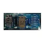
Most socket adapters program a single device at a time
and take up one socket site. Dual socket adapters cover
two socket sites, but each IC has a dedicated set of status
LEDs on the PCB as shown in Figure 1.
The socket adapters employ ESD-sensitive components.
Observe safe ESD practices when handling the socket
adapters.
Figure 1. Single and Dual IC Socket Adapters
www.maximintegrated.com
Maxim Integrated │ 2
�DS9488-GP8/DS9122x
Evaluation System
Application Installation
1) Download the latest version of the 1-Wire + I2C
Multi-Device Programmer software from the Maxim
website. Note that a free account is required to
download software from the Maxim website.
2) While observing safe ESD practices, carefully
remove the DS9488-GP8 board from its packaging.
Inspect the board to ensure that no damage occurred during shipment.
3) Connect the DS9488-GP8 to a PC using the
supplied USB cable. All LEDs on the DS9488-GP8
momentarily illuminate. One or more LEDs might
remain on. The DS9488-GP8 must be connected
during application installation.
4) Click on the setup application to begin installation.
5) Follow the installation instructions. If prompted, allow
the DS9488-GP8 USB drivers to be installed.
6) Install the desired device-specific plugins for
programming.
Multi-Device Programmer for
1-Wire and I2C Devices
Device-Specific Plugin Installation
Install device-specific plugins using the application.
1) Obtain the compressed plugin package from Maxim.
The package name incorporates the name of the
device. For example, DS2431 Programmer Plugin
supports all packages of the DS2431.
2) Navigate to the Application Setup tab and click on
the Device Plugins radio button. See Figure 2.
3) Click on the View Device Folder button. Copy the
package into the displayed folder.
4) Extract the .dll file and .pdf file for each device.
5) The plugins in this folder are automatically loaded
when the application is launched. To load a plugin for
immediate use, click on the Load Device Plugin button and select the corresponding .dll file.
Figure 2. Loaded Device Plugins
www.maximintegrated.com
Maxim Integrated │ 3
�DS9488-GP8/DS9122x
Evaluation System
Programming
If socket adapters have not been installed, remove power
from the DS9488-GP8. Install the socket adapters, and
reapply power.
The programming procedure has three steps:
●●
Device configuration
●●
Production file creation
●●
Programming
Multi-Device Programmer for
1-Wire and I2C Devices
Device Configuration
1) Navigate to the Device Configuration tab, shown in
Figure 3.
2) Select the device type to be programmed.
3) Configure the device-specific options. Information
about the options can be found in the IC data sheet
and also in .pdf files under the Application Setup
tab, View Device Help.
4) If desired, click Save As... to record the configuration
options.
Figure 3. Device Configuration
www.maximintegrated.com
Maxim Integrated │ 4
�DS9488-GP8/DS9122x
Evaluation System
Production File Creation
The production file compiles all the configuration information and data into a single .xml file to be used by the programmer. After the device configuration has been input,
press the Production File Create button and save the
file to the folder defined in the Application Setup, File
Outputs field.
The programmer offers the option to encrypt the production file for secure transfer between sites.
Programming
1) Populate the desired sockets.
2) Navigate to the Programmer tab and select the
active sockets as shown in Figure 4. An error is
generated during programming if an active socket is
not populated with an IC.
Multi-Device Programmer for
1-Wire and I2C Devices
3) Make sure the programmer is connected. If not, select Auto Detect under the COM button. Then click
on the Connect button. The text below the Connect
button indicates the programmer is connected.
4) Load a previously generated production file using the
Load Production File... button.
5) Press either Start button on the programmer board
or the Start button on the Programmer tab. The
active LEDs on each socket board illuminate during
programming and the progress bar advances.
6) When programing is complete, the ALL PASS indicator on the programmer is green if all devices programmed and verified correctly. The indicator is red if
any of the devices fail verification.
7) The application keeps a running summary of the programming session. The cumulative results of each
session are logged in the Outputs folder.
Figure 4. Programming Dialog
www.maximintegrated.com
Maxim Integrated │ 5
�DS9488-GP8/DS9122x
Evaluation System
Figure 5 shows the application following a programming
session in which sockets 1–5 are populated, and socket
4 failed post-programming verification. Figure 6 shows
the programmer hardware after the same programming
session with the pass/fail LEDs illuminated.
Production File Encryption
The application provides the option to encrypt production
files so they can be securely transferred between a master (configuration) system and one or more programming
systems. The application generates an RSA public/private
Multi-Device Programmer for
1-Wire and I2C Devices
key pair that is used for the encryption and decryption.
Figure 7 illustrates the procedure for generating and
installing encryption keys and creating and loading an
encrypted production file. One key pair should be created
by the master system and shared among all the programming systems.
The application loads both encrypted and nonencrypted
production files if encryption keys are installed. Attempts
to load an encrypted production file without first installing
the encryption keys generate an error.
Figure 5. Example Session—GUI
www.maximintegrated.com
Maxim Integrated │ 6
�DS9488-GP8/DS9122x
Evaluation System
Multi-Device Programmer for
1-Wire and I2C Devices
Figure 6. Example Session—Programmer
CONFIGURATION SYSTEM
PROGRAMMING SYSTEM
CONFIGURE DEVICE
SAVE
DECRYPTION_PRIVATE_USECURED.KEY
ENCRYPTION_PUBLIC.KEY
IN KEYS FOLDER
INSTALL ENCRYPTION (PUBLIC) KEY
CREATE ENCRYPTED PRODUCTION FILE
SECURELY TRANSPORT
DECRYPTION_PRIVATE_UNSECURED.KEY
TO PROGRAMMING SYSTEM
INSTALL DECRYPTION (PRIVATE) KEY
TO CREATE
DECRYPTION_PRIVATE_SECURED.KEY
DELETE
DECRYPTION_PRIVATE_USECURED.KEY*
LOAD ENCRYPTED PRODUCTION FILE
* FAILURE TO DELETE DECRYPTION_PRIVATE_UNSECURED.KEY FROM
THE PROGRAMMING SYSTEM COMPROMISES THE SECURITY OF THE ENCRYPTION PROTOCOL.
Figure 7. Using Encrypted Production Files
www.maximintegrated.com
Maxim Integrated │ 7
�DS9488-GP8/DS9122x
Evaluation System
Key Generation and Installation
1) On the master system, navigate to Generate Key Pair
under the Application Setup → Encryption Keys
dialog. Two keys are generated in the Keys folder:
• decryption_private_unsecured.key (unencrypted
1024-bit private key)
• encryption_public.key (unencrypted 1024-bit public
key)
2) Install the public key on the master system by clicking on the Install Encryption (Public) Key button
and selecting encryption_public.key.
3) Securely transport decryption_private_unsecured.
key to the keys directory of the programming system.
4) On the programming system navigate to the Application Setup → Encryption Keys dialog. Click
Install Decryption (Private) Key and select decryption_private_unsecured.key. This creates a new
encrypted private key (decryption_private_secured.
key) using the Windows Data Protection API that is
unique to the production computer.
5) Erase privkey_unencrypted.key from the programming system.
Producing Encrypted Production Files
1) Load or create a configuration through the Device
Configuration tab.
2) Select the Encrypt option.
3) Press the Create button. The production file is
encrypted using the public key and placed in the
outputs folder.
www.maximintegrated.com
Multi-Device Programmer for
1-Wire and I2C Devices
Troubleshooting
Programming failures can sometimes be caused by incorrect settings in the Device Options dialog. Refer to the
appropriate data sheet for details of the configuration
options.
The application keeps a detailed log of the programmer
sessions, which can be used to troubleshoot problems.
The log file is in .txt format and located in the Outputs
folder.
Go to support.maximintegrated.com/micro for technical
support.
Component List, Schematics, and PCB
Layout
See the following links for component information, schematics, and PCB layout:
●● DS9488 BOM
●● DS9488 schematic
●● DS9488 PCB layout
●● DS9122P BOM
●● DS9122P schematic
●● DS9122P PCB layout
●● DS9122Q BOM
●● DS9122Q schematic
●● DS9122Q PCB layout
Maxim Integrated │ 8
�DS9488-GP8/DS9122x
Evaluation System
Multi-Device Programmer for
1-Wire and I2C Devices
Ordering Information
PART
TYPE
DS9488-GP8#
multi-device
programmer
SUPPORTED DEVICES
8-socket
DS9122P#
DS9122Q#
—
6-pin TSOC dual socket adapter
DS2431P
DS28E15P
DS28E22P
DS28E25P
DS2431P-A1
DS28EL15P
DS28EL22P
DS28EL25P
6-pin TDFN (3mm x 3mm)socket
adapter
DS2431Q
DS28E15Q
DS28EL15Q
DS28EL22Q
DS28EL25Q
DS28E22Q
DS28E25Q
#Denotes RoHS compliant.
*Future product—contact factory for availability.
Device-Specific Plugins for Programming
DEVICE PLUGIN
AVAILABILITY
SUPPORTED DEVICES
DS2431
Online
DS2431P
DS2431Q
DS2431P-A1
Under NDA
DS28E15P
DS28E15Q
DS28EL15P
DS28EL15Q
DS28E22P
DS28E22Q
DS28EL22P
DS28EL22Q
DS28E25P
DS28E25Q
DS28EL25P
DS28EL25Q
DS28E(L)15_22_25
www.maximintegrated.com
Maxim Integrated │ 9
�DS9488-GP8/DS9122x
Evaluation System
Multi-Device Programmer for
1-Wire and I2C Devices
Revision History
REVISION
NUMBER
REVISION
DATE
0
11/15
Initial release
5/16
Updated Benefits and Features, EV System Contents, Required Equipment,
Selecting Socket Adapters, Applicatoin Installation, Device-Specific Plugin
Installation, Component List, Schematics, and PCB Layout, and Ordering
Information sections, and added Device-Specific Plugins for Programming section
1
PAGES
CHANGED
DESCRIPTION
—
1, 2, 3, 8, 9
For pricing, delivery, and ordering information, please contact Maxim Direct at 1-888-629-4642, or visit Maxim Integrated’s website at www.maximintegrated.com.
Maxim Integrated cannot assume responsibility for use of any circuitry other than circuitry entirely embodied in a Maxim Integrated product. No circuit patent licenses
are implied. Maxim Integrated reserves the right to change the circuitry and specifications without notice at any time.
Maxim Integrated and the Maxim Integrated logo are trademarks of Maxim Integrated Products, Inc.
© 2016 Maxim Integrated Products, Inc. │ 10
�DS9488-GP8 BILL OF MATERIALS (BOM); Rev 0; 11/15
Designator
C1, C2, C3, C5, C11
C4, C6, C8, C10, C12, C13, C16, C18, C19, C20, C21, C22, C23,
C24, C25, C26, C27, C28, C29, C30, C31, C32, C33, C34, C35
Quantity
Description
5 1uF Ceramic Capacitor (0603)
25 0.1uF Ceramic Capacitor (0603)
Manufacture Name
LMK107B7105KA-T
Kemet
C0603C104K4RACTU, C0603C104K8RACTU
C1608C0G1H180J080AA
GRM21BF51C225ZA01L
C2012X5R1A106K125AB
10103594-0001LF
SBR05U20SN-7
LTST-C193KRKT-5A
598-8081-107F
150060YS75000
LB Q39G-L2N2-35-1
BLM21PG221SN1D
5104338-1
PMSSS 440 0025 PH
2203
PMV65XP,215
BSS138LT1G
BSS138LT1G
ERJ-3EKF1741V
ERJ-3GEYJ473V
RC0603FR-07100KL
RC0603FR-071KL
RC0603FR-074R99L
ERA-3AEB513V
ERA-3AEB4122V
ERA-3AEB1073V
ERJ-8GEYJ100V
ERJ-3EKF1501V
ERJ-3EKF1622V
ERJ-3EKF3301V
CRCW06032K43FKEA
ERJ-3EKF4701V
MF-NSMF012-2
B3U-1000P
B3F-4055
B32-1350
SSA12
PPPC061LFBN-RC
PPPC031LFBN-RC
MAXQ622G-0000+
MAX14661ETI+
DS2484R+
MAX8892EXK+
MAX3207EAUT+
MAX13204EALT+
ECS-120-20-3X-TR
C7, C9
2 18pF Ceramic Capaitor (0603)
TDK Corporation
C14, C17
2 2.2uF Ceramic Capacitor (0805)
Murata Electronics North America
C15
1 10uF Ceramic Capacitor (0805)
TDK Corporation
CN1
1 USB Micro B Connector
FCI
D1
1 Common Cathode Diode
Diodes Inc
D2
1 Red LED (0603)
Lite-On Inc
D3
1 Green LED (0603)
Dialight
D4
1 Yellow LED (0603)
Wurth Electronics Inc
D5
1 Blue LED (0603)
OSRAM Opto Semiconductors Inc
FB1
1 Ferrite (0603)
Murata Electronics North America
J1
1 10 Pin JTAG Connector
TE Connectivity
MechSC1 - MechSC20
20 4-40x1/4" Machine Screw
B&F Fastener Supply
MechSO1 - MechSO20
20 Aluminum Standoff
Keystone Electronics
Q1, Q2, Q3, Q5
4 P-Channel MOSFET (SOT-23)
International Rectifier
Q4, Q6, Q8, Q9
4 N-Channel MOSFET(SOT-23)
ON SEMICONDUCTOR
Q7
1 N-Channel MOSFET(SOT-23)
ON SEMICONDUCTOR
R1, R2, R3, R4
4 1.74kΩ Resistor (0603)
Panasonic Electronic Components
R5, R7, R9
3 47kΩ Resistor (0603)
Panasonic Electronic Components
R6, R11, R20, R22, R29
5 100kΩ Resistor (0603)
Yageo
R8, R12, R24, R26
4 1Ω Resistor (0603)
Yageo
R10, R13
2 4.99Ω Resistor (0603)
Yageo
R14
1 51kΩ Resistor (0603)
Panasonic Electronic Components
R15
1 41.2kΩ Resistor (0603)
Panasonic Electronic Components
R16
1 107kΩ Resistor (0603)
Panasonic Electronic Components
R17
1 10Ω Resistor (0603)
Panasonic Electronic Components
R18
1 1.5kΩ Resistor (0603)
Panasonic Electronic Components
R19
1 16kΩ Resistor (0603)
Panasonic Electronic Components
R21, R25, R28, R30
4 3.3kΩ Resistor (0603)
Panasonic Electronic Components
R23
1 2.4kΩ Resistor (0603)
Vishay Dale
R27
1 4.7kΩ Resistor (0603)
Panasonic Electronic Components
RT1
1 PTC Fuse (1206)
Bourns Inc.
S1
1 Tactile Switch
Omron Electronics Inc
S2, S4
2 Tactile Switch
Omron Electronics Inc
MechS2, MechS4
2 Square Green Switch Cap
Omron Electronics Inc
1 Do Not Populate
TE Connectivity
S3
SR1 - SR16
16 6 Pin Connector
Sullins Connector Solutions
ST1 - ST16
16 3 Pin Connector
Sullins Connector Solutions
U1
1 16-Bit Microcontrollers with Infrared Module and Optional USB
Maxim Integrated
U2, U4
2 Beyond-the-Rails 16:2 Multiplexer
Maxim Integrated
U3, U6
2 I2C To 1-Wire Master
Maxim Integrated
U5
1 High PSRR, Low-Dropout, 150mA Linear Regulator
Maxim Integrated
U7
1 Dual High-Speed Differential ESD-Protection IC
U8 - U23
X1
16 4 Channel +/- 30kv ESD Protector
1 12MHz Crystal
Part Number
Taiyo Yuden
Maxim Integrated
Maxim Integrated
ECS Inc.
�1
2
A
POP001
P0.1
POP002
P0.2
POP003
P0.3
POP004
P0.4
POP005
P0.5
POP006
P0.6
POP007
P0.7
NLP001
P0.1
NLP002
P0.2
NLP003
P0.3
NLP004
P0.4
NLP005
P0.5
NLP006
P0.6
NLP007
P0.7
POP300
P3.0
POP301
P3.1
POP302
P3.2
POP303
P3.3
POP304
P3.4
POP305
P3.5
POP306
P3.6
POP307
P3.7
NLP300
P3.0
NLP301
P3.1
NLP302
P3.2
NLP303
P3.3
NLP304
P3.4
NLP305
P3.5
NLP306
P3.6
NLP307
P3.7
27
PIU1027
28
PIU1028
29
PIU1029
30
PIU1030
31
PIU1031
32
PIU1032
33
PIU1033
34
PIU1034
P3.0/INT8
P3.1/INT9
P3.2/INT10
P3.3/INT11
P3.4/INT12
P3.5/INT13
P3.6/INT14
P3.7/INT15
NLP400
P4.0
55
PIU1055
56
PIU1056
57
PIU1057
58
PIU1058
59
PIU1059
60
PIU1060
61
PIU1061
62
PIU1062
P4.0
P4.1
P4.2
P4.3
P4.4
P4.5
P4.6
P4.7
PIR902
COR9
R9
47k
PIR901
NLP401
P4.1
NLP402
P4.2
NLP403
P4.3
NLP404
P4.4
NLP405
P4.5
NLP406
P4.6
NLP407
P4.7
MRSTb
PIS102
COS1
S1
PIC10 1
PIC10 2
PUSH
PIS101
COC10
C10
0.1uF
PIC1 01
PIC1 02
15
PIU1015
23
PIU1023
8
PIU108
17
PIU1017
24
PIU1024
COC11
C11
1uF
5
P0.0/IRTXM
P0.1/RX0
P0.2/TX0
P0.3/RX1/SDA
P0.4/TX1/SCL
P0.5/TBA0/TBA1
P0.6/TBB0
P0.7/TBB1
22
VDD
VDDIO
VDDB
VBUS
PIU1022
21
PIU1021
DP
DM
PIU1016
18
PIU1018
P2.0/MOSI0
P2.1/MISO0
P2.2/SCLK0
P2.3/SSEL0
P2.4/TCK
P2.5/TDI
P2.6/TMS
P2.7/TDO
P1.0/INT0
P1.1/INT1
P1.2/INT2
P1.3/INT3
P1.4/INT4
P1.5/INT5
P1.6/INT6
P1.7/INT7
16
45
49
50
51
52
PIU1052
53
PIU1053
54
PIU1054
PIU1049
PIU1050
PIU1051
PIU1037
HFXOUT
HFXIN
PIU1026
GND
GND
PIU1035
RESET
REG18
GND
GND
GND
COC1
C1
1uF
PIC201
PIC301
COC2
C2
PIC202
1uF
PIC302
COC3
C3
1uF
PIC401
COC4
C4
0.1uF
PIC402
PIC501
PIC502
VCC
COC5
C5
PIC602
COR1
R1
PIR102
1.74k
PIR101
COR2
R2
1.74k
GND
PIR201
COR3
R3
1.74k
PIR302
PIR301
COR4
R4
1.74k
PIR402
PIR401
Rp for FAST MODE CB=200pF
40
PIU1040
26
25
PIC701
PIX102
PIU1025
35
63
PIX101
PIU1063
1PIU201
SPI/I2C
VCC
PIU2026
NLSDA0PRGM 10PIU2010
SDA_PRGM
COM-A
AB01
AB02
AB03
AB04
AB05
AB06
AB07
AB08
PIU202
AB09
AB10
AB11
AB12
AB13
AB14
AB15
AB16
PIU2021
GND
NLSCL0PRGM 13
SCL_PRGM
PIU2013
VCC
COR5
R5
47k
PIR502
PIR501
VCC
GND
VCC
COR6
R6
100K
COR7
R7
47k
PIR702
COS2
S2
B3F-4055
PIC901 PIC902
PIS201
18pF
PIC1201
PIC1202
PIS402
COS4
S4
COC12
C12
0.1uF
B3F-4055
PIS401
PIC3501
PIC3502
22PIU2022
23PIU2023
SCL_CTRL 24PIU2024
SDA_CTRL 27PIU2027
28PIU2028
G
PIQ103
NLSLPZ0A
SLPZ_A
SDA_PRGM
SCL_PRGM
COC35
C35
0.1uF
COU3
U3
1PIU301
SLPZ VCC
2PIU302
SDA
IO
3PIU303
SCL GND
PIR802
COR10
R10
4.99
6
4
PIU304
PIC1301
PIC1302
COU4
U4
1PIU401
SPI/I2C
COC13
C13
0.1uFVCC
*TOP CAP PART # SW1138-ND
GND
PIR1402
COR14
R14
51k
PID103
1
OUT
IN PIU501
2
GND PIU502
3
FB SHDN PIU503
COR11
R11
100K
COFB1
FB1
PIFB102
BAT54C
PIFB101
CORT1
RT1
PTC Fuse MF-NSMF012-2
PIRT102
BLM21PG221SN1D
PICN1065 PICN10 4 PICN10 3 PICN109 PICN108 COCN1
PIC1401
PIC1402
PIR1401
COU7
U7
C14
COC14
2.2uF
COR15
R15
3.3V_N
PIR1502
PIR1501
PIR1602
C
PIC1701
PIC1702
OPTIONAL
COS3
S3
PIS301
41.2k
PIS302
PIC1801
PIC1802
COC17
C17
2.2uF
PIU702
VCC
GND
I/O1
I/O2
PIU701
PIU704
PIRT101
1
V+
2
D3
D+
4
PICN104
5
PICN105 VPICN101
NLMDM
MDM
NLMDP
MDP
PICN103
DNP
1
PIU601 SLPZ VCC
2PIU602
SDA
IO
3PIU603
SCL GND
4
PIU604
PIR1301
1WB
NL1WB
PIC1601
PIC1602
22
PIU4022
23PIU4023
NLSCL0CTRL 24PIU4024
SCL_CTRL
NLSDA0CTRL 27
SDA_CTRL
PIU4027
28PIU4028
COR13
R13
4.99
6
PIU606
5
PIU605
DS2484
I2C W ADD 0x30
PICN102
MAX3207EAUT+T
PIS303
COR16
R16
107k
6
1
4
3
PIU703
PIU706
5
2
PIU705
COC18
C18
0.1uF
CN1
USB Micro B
NLSLPZ0B
SLPZ_B
SDA_CTRL
SCL_CTRL
NLSD0N
SD_N
PIR1302
COU6
U6
GND
SD
CS/A0
SCLK/SCL
DIN/SDA
DOUT/A1
12PIU4012
NC
11PIU4011
GND
25PIU4025
GND
EPPIU40EP
GND
COC16
C16
0.1uF
4
5
PIU205
6
PIU206
7
PIU207
8
PIU208
9
PIU209
PIU204
21
20
PIU2020
19
PIU2019
18
17
PIU2017
16
PIU2016
15
PIU2015
14
PIU2014
PIU2018
GND
NLI2C0AB01
I2C_AB01
NLI2C0AB02
I2C_AB02
NLI2C0AB03
I2C_AB03
NLI2C0AB04
I2C_AB04
NLI2C0AB05
I2C_AB05
NLI2C0AB06
I2C_AB06
NLI2C0AB07
I2C_AB07
NLI2C0AB08
I2C_AB08
NLI2C0AB09
I2C_AB09
NLI2C0AB10
I2C_AB10
NLI2C0AB11
I2C_AB11
NLI2C0AB12
I2C_AB12
NLI2C0AB13
I2C_AB13
NLI2C0AB14
I2C_AB14
NLI2C0AB15
I2C_AB15
NLI2C0AB16
I2C_AB16
Stand Off (Qty. 20)
POI2C0AB01
I2C_AB01
POI2C0AB02
I2C_AB02
POI2C0AB03
I2C_AB03
POI2C0AB04
I2C_AB04
POI2C0AB05
I2C_AB05
POI2C0AB06
I2C_AB06
POI2C0AB07
I2C_AB07
POI2C0AB08
I2C_AB08
COMechS2
MechS2
COMechS4
MechS4
Switch Cap
Switch Cap
POI2C0AB09
I2C_AB09
POI2C0AB10
I2C_AB10
POI2C0AB11
I2C_AB11
POI2C0AB12
I2C_AB12
POI2C0AB13
I2C_AB13
POI2C0AB14
I2C_AB14
POI2C0AB15
I2C_AB15
POI2C0AB16
I2C_AB16
VCC
B
PIC801
PIC802
COC8
C8
0.1uF
26
VCC
PIU4026
2
PIU402
AB01
AB02
AB03
AB04
AB05
AB06
AB07
AB08
3
4
PIU404
5
PIU405
6
PIU406
7
PIU407
8
PIU408
9
PIU409
PIU403
21
AB09
AB10
AB11
AB12
AB13
AB14
AB15
AB16
PIU4021
20
PIU4020
19
PIU4019
18
PIU4018
17
16
PIU4016
15
PIU4015
14
PIU4014
PIU4017
GND
NL1W0AB01
1W_AB01
NL1W0AB02
1W_AB02
1W_AB03
NL1W0AB03
NL1W0AB04
1W_AB04
NL1W0AB05
1W_AB05
NL1W0AB06
1W_AB06
NL1W0AB07
1W_AB07
1W_AB08
NL1W0AB08
NL1W0AB09
1W_AB09
NL1W0AB10
1W_AB10
NL1W0AB11
1W_AB11
1W_AB12
NL1W0AB12
NL1W0AB13
1W_AB13
NL1W0AB14
1W_AB14
NL1W0AB15
1W_AB15
NL1W0AB16
1W_AB16
PO1W0AB01
1W_AB01
PO1W0AB02
1W_AB02
PO1W0AB03
1W_AB03
PO1W0AB04
1W_AB04
1W_AB05
PO1W0AB05
PO1W0AB06
1W_AB06
PO1W0AB07
1W_AB07
PO1W0AB08
1W_AB08
1W_AB09
PO1W0AB09
PO1W0AB10
1W_AB10
PO1W0AB11
1W_AB11
PO1W0AB12
1W_AB12
PO1W0AB13
1W_AB13
1W_AB14
PO1W0AB14
PO1W0AB15
1W_AB15
PO1W0AB16
1W_AB16
MAX14661
I2C WRITE ADD 0x98
GND
S
S
COC15
C15
10uF
PIQ203
PIR1202
1k
VCC
COM-B
G
D
PID102
PID101
MAX8892
PIC1501
PIC1502
13PIU4013
S
COM-A
PIQ201
COR12
PPIR1201
IR1 01 R12
1-WB_DPUZ
NL10WB0DPUZ
t
4
PIU504
PIQ20
Q2
COQ2
PMV65XP
PIR1 02
VCC5.0
S
S
5
PIU505
JTAG V5.0 OUT
D1
COD1
VCC4.5
15
14
13
9
8
U5
COU5
GND
2
MAX14661
I2C WRITE ADD 0x9A
GND
10PIU4010
GND
26
3
PIU203
PIR10 1
NL1WA
1WA
DS2484
I2C W ADD 0x30
SD
CS/A0
SCLK/SCL
DIN/SDA
DOUT/A1
PIR10 2
1k
PIU306
5
PIU305
COM-B
12PIU2012
NC
11PIU2011
GND
25PIU2025
GND
EPPIU20EP
GND
S
PIQ101
COR8
PPIR801
IR601 R8
VCC
PIS202
SD_N
D
NL10WA0DPUZ
1-WA_DPUZ
PIC702
PIQ102
COQ1
Q1
PMV65XP
PIR602
PIR701
COX1
X1
18pF
12MHz C9
COC9
COMechSO1- MechSO20
0 MechSO20
MechSO1
COC6
C6
0.1uF
COU2
U2
PIR202
YELLOW LED
VCC5_AUX_EN
NLSTART0N
START_N
COC7
C7
PIU1038
39
PIU1039
PIJ1010
Screw (Qty. 20)
PIC601
1uF
NL303V0N
3.3V_N
37
38
P5.0/MOSI1
P5.1/MISO1
P5.2/SCLK1
P5.3/SSEL1
PIC102
SLPZ_A
SLPZ_B
SD_N
VCC_AUX_N
1-WA_DPUZ
1-WB_DPUZ
1WA
1WB
PIU1045
48
PIU1048
PIJ106
JTAG
PIJ108
A
PIC101
SDA_PRGM
SCL_PRGM
SDA_CTRL
SCL_CTRL
BLED_TCK
TDI
GLED_TMS
RLED_TDO
12
13
PIU1013
14
PIU1014
41
PIU1041
42
PIU1042
43
PIU1043
44
PIU1044
PIU1012
NLVCC
VCC


 工商网监
湘ICP备2023018690号
工商网监
湘ICP备2023018690号
