AIDW40S65C5
CoolSiC™ Automotive Schottky Diode 650V G5
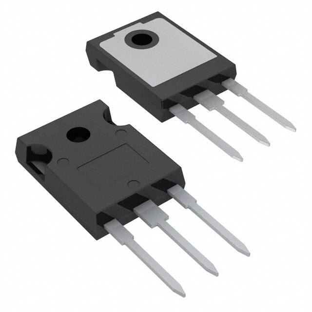
650V/40A Silicon Carbide Schottky Diode in TO247-3
Features
Revolutionary semiconductor material - Silicon Carbide
Benchmark switching behavior
No reverse recovery/ No forward recovery
Temperature independent switching behavior
High surge current capability
Pb-free lead plating; RoHS compliant
Junction Temperature range from -40°C to 175°C
System efficiency improvement over Si diodes
System cost / size savings due to reduced cooling requirements
Enabling higher frequency / increased power density solutions
Higher system reliability due to lower operating temperatures
Reduced EMI
Potential Applications
Traction inverter
Booster / DCDC Converter
On board Charger / PFC
Product Validation
“Qualified for Automotive Applications. Product Validation according to AEC-Q100/101”
Description
The 5th Generation CoolSiC™ Automotive Schottky Diode represents Infineon leading edge technology for
Silicon Carbide Schottky Barrier diodes. Thanks to a compact design and a technology based on thin wafers,
this family of products shows improved efficiency over all load conditions resulting from both its thermal
characteristics and low figure of merit (Qc x Vf). This product family has been designed to complement
Infineon’s IGBT and CoolMOS™ portfolio. This ensures meeting the most stringent application requirements in
the 650V voltage class.
Product Information
Parameter
Value/Unit
Pin
Ordering Code AIDW40S65C5
VDC,max
650 V
Pin 2, case Cathode
Marking
AD4065C5
IF; TC< 117 °C 40 A
Package
PG-TO247-3-41
QC; VR= 400 V 56 nC
SP Number
SP001725204
EC; VR= 400 V 12.9 μJ
Tj,max
Datasheet
www.infineon.com
Pin 3
Definition
Anode
175 °C
Please read the Important Notice and Warnings at the end of this document
Page 1 of 11
V3.0
26.11.2018
�CoolSiC™ Automotive Schottky Diode 650V G5
650V/40A Silicon Carbide Schottky Diode in TO247-3
Table of Contents
Table of Contents
Features…………………………………………………………………………………………………………..………..………..…
1
1
Potential Applications………………………………………………………………………………………..………………………
1
Product Validation………………………………………………..……………………………………………………………………
Description……………………………………………..………………………………………………………………………………
1
Table of Contents……………………………………………..………………………………………………………………………
2
1
Maximum Ratings…………………………………………..……………………………………………………………………
3
2
Thermal Characteristics………………………………………..………………………………………………………………
4
3
Electrical Characteristics……………………………………………..…………………………………………………………
5
4
6
Electrical Characteristics Diagrams…………………………………………..………………………………………………
5
9
Package Outlines………………………………………………………………………..………………………………………
Revision History………………………………………………………………………..………………………………………………
10
Datasheet
Page 2 of 11
V3.0
26.11.2018
�CoolSiC™ Automotive Schottky Diode 650V G5
650V/40A Silicon Carbide Schottky Diode in TO247-3
Maximum Ratings
1
Maximum Ratings
Table 1
Maximum ratings 1
Parameter
Repetitive peak reverse voltage
Continuous forward current for RthJC,max
TC = 117 °C, D=1
Surge non-repetitive forward current,
sine halfwave
TC= 25°C, tp=10ms
Symbol
Value
Unit
VRRM
650
V
IF
40
A
IF,SM
182
A
TC= 150°C, tp=10ms
153
Non-repetitive peak forward current
TC= 25°C, tp=10μs
i²t value
TC= 25°C, tp=10ms
IF,max
1432
A
∫i2 dt
166
A2s
TC= 150°C, tp=10ms
118
Diode dv/dt ruggedness
VR=0...480V
dv/dt
100
V/ns
Ptot
183
W
Tj
-40…175
°C
Tstg
-55…150
°C
Human body model, R= 1.5 kΩ, C = 100 pF
8
kV
Charged device model
2
Power dissipation
TC = 25°C
Operating temperature
Storage temperature
ESD
Soldering temperature,
wavesoldering only allowed at leads,
1.6mm (0.063 in.) from case for 10 s
Tsold
Mounting Torque (M3 and M4 screws)
Datasheet
Page 3 of 11
260
°C
70
Ncm
V3.0
26.11.2018
�CoolSiC™ Automotive Schottky Diode 650V G5
650V/40A Silicon Carbide Schottky Diode in TO247-3
Thermal Characteristics
2
Thermal Characteristics
Table 2
Thermal Characteristics
1
Values
Parameter
Symbol
Unit
Note/Test condition
Min. Typ. Max.
Thermal resistance, junction–case2
Thermal resistance, junction-ambient
Datasheet
2
RthJC
-
0.6
0.8
K/W
RthJA
-
-
62
K/W
Page 4 of 11
V3.0
26.11.2018
�CoolSiC™ Automotive Schottky Diode 650V G5
650V/40A Silicon Carbide Schottky Diode in TO247-3
Electrical Characteristics
3
Electrical Characteristics
Table 3
Static Characteristics
Values
Parameter
Symbol
Unit
Note/Test condition
Min. Typ. Max.
DC blocking voltage
VDC
Diode forward voltage3
VF
Reverse current
IR
Table 4
650
-
-
-
1.5
1.7
-
1.8
2.1
-
7
120
-
47
-
Tj = 25°C, IR = 0.12 mA
V
Tj = 25°C, IF = 40 A
Tj = 150°C, IF = 40 A
µA
VR = 650 V, Tj = 25 °C
VR = 650 V, Tj = 150 °C
Dynamic Characteristics at Tj=25°C unless noted otherwise
Values
Parameter
Symbol
Unit
Note/Test condition
Min. Typ. Max.
Total capacitive charge
Total capacitance
QC
C
nC
VR = 400 V, di/dt = 200 A/µs,
IF ≤ IF,MAX, Tj = 150 °C
-
56
-
-
1138
-
-
148
-
pF VR = 300 V, f = 1 MHz
-
145
-
VR = 600 V, f = 1 MHz
VR = 1 V, f = 1 MHz
Footnotes:
1
2
3
The parameter is not subject to production test- verified by design/characterization.
Rth,JC defined as per JESD-51-14. Rth,JA defined as per JESD-51-2.
Only the value at 25°C is subject to production test. The value at 150°C is only verified by design/characterization.
Datasheet
Page 5 of 11
V3.0
26.11.2018
�CoolSiC™ Automotive Schottky Diode 650V G5
650V/40A Silicon Carbide Schottky Diode in TO247-3
Electrical Characteristics Diagrams
4
Electrical Characteristics Diagrams
Figure 1
(LEFT) Power dissipation; P tot= f(TC); RthJC,max
(RIGHT) Diode forward current; I F= f(TC); Tj≤ 175 °C; RthJC,max; parameter: D=duty cycle
Figure 2
Datasheet
(LEFT) Typical forward characteristic; I F= f(VF); tP=200 μs; parameter:Tj
(RIGHT) Typical forward characteristics in surge current; I F= f(VF); tP=200 μs; parameter:Tj
Page 6 of 11
V3.0
26.11.2018
�CoolSiC™ Automotive Schottky Diode 650V G5
650V/40A Silicon Carbide Schottky Diode in TO247-3
Electrical Characteristics Diagrams
Figure 3
(LEFT) Typical capacitive charge versus current slope (only capacitive charge, guaranteed
by design); QC= f(diF/dt); Tj=150°C; VR=400V; IF ≤ IF,max
(RIGHT) Typical reverse current versus reverse voltage; I R= f(VR);parameter: Tj
i
ri [K/W]
1
2
3
4
2.08E-02 2.04E-01 2.41E-01 1.64E-01
Ti [s]
7.23E-06 4.40E-04 2.88E-03 1.10E-02
Figure 4
Datasheet
(LEFT) Max. Transient thermal impedance; Z thJC= f(tP); parameter:D=tP/T
(RIGHT) Typ. Capacitance vs. Reverse voltage; C= f(V R); Tj=25°C; f=1 MHz
Page 7 of 11
V3.0
26.11.2018
�CoolSiC™ Automotive Schottky Diode 650V G5
650V/40A Silicon Carbide Schottky Diode in TO247-3
Electrical Characteristics Diagrams
Figure 5
Figure 6
Typical capacitance stored energy; E C= f(VR)
-9.2E-04 [V/°C]
B=
1.0E+00 [V]
C=
3.2E-07 [Ω/(°C)2]
D=
1.8E-05 [Ω/°C]
E=
1.0E-02 [Ω]
Simplified forward characteristics model V F= f(IF);
-40°C < Tj
很抱歉,暂时无法提供与“AIDW40S65C5XKSA1”相匹配的价格&库存,您可以联系我们找货
免费人工找货- 国内价格 香港价格
- 240+72.74810240+9.39849