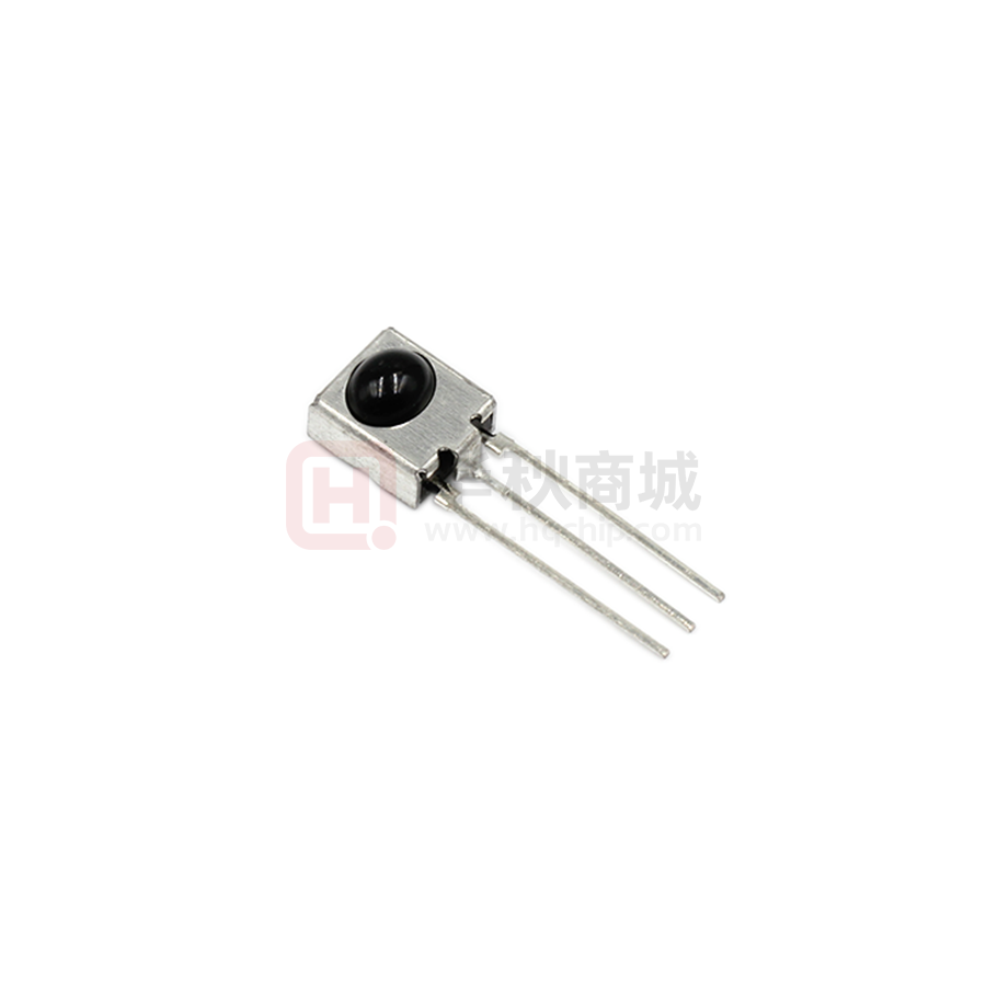
Infrared Remote Control Receiver Module
IRM-8601M2-X Series
Block Diagram
Pin Configuration
1. OUT
2. GND
3. VCC
1
2
3
Features
‧ High protection ability against EMI
‧ Ellipsoid lens for improved reception characteristics
‧ Available for various carrier frequencies
‧ Min burst length: 10 cycles
‧ Min gap length: 14 cycles
‧ Low operating voltage and low power consumption
‧ High immunity against ambient light
‧ High immunity against TFT backlight
‧ Long reception range
‧ High sensitivity
‧ Pb free and RoHS compliant
Description
The IRM-8601M2-X devices are DIP type infrared
receivers which have been developed and designed by
using the latest IC technology.
The PIN diode and preamplifier are assembled onto a
lead frame and molded into a black epoxy package
which operates as an IR filter.The demodulated
output signal can directly be decoded by a
microprocessor.
1
Copyright © 2013, Everlight All Rights Reserved. Release Date : 27/1/2014 Issue No: DMO-0000183 Rev:2
www.everlight.com
�Data Sheet
Infrared Remote Control Receiver Module
IRM-8601M2-X Series Datasheet
Applications
• AV equipment such as TV, VCR, DVD, CD, MD, etc.
• CATV set top boxes
• Multi-media Equipment
• Other devices using IR remote control
Application Circuit
The RC Filter must be connected as close as possible to Vcc and GND pins.
Parts Table
2
Model No.
Carrier Frequency
IRM-8601M2-2
36 kHz
IRM-8601M2
38 kHz
IRM-8601M2-4
40 kHz
Copyright © 2013, Everlight All Rights Reserved. Release Date : 27/1/2014 Issue No: DMO-0000183 Rev:2
www.everlight.com
�Data Sheet
Infrared Remote Control Receiver Module
IRM-8601M2-X Series Datasheet
Absolute Maximum Ratings (Ta=25°C)
Parameter
Symbol
Rating
Unit
Supply Voltage
Vcc
6
V
Operating Temperature
Topr
-20 ~ +80
℃
Storage Temperature
Tstg
-40 ~ +85
℃
Tsol
260
℃
Soldering Temperature
*1
*1
4mm from mold body for less than 5 seconds
Electro-Optical Characteristics (Ta=25℃, Vcc=3V)
Parameter
Symbol
MIN.
TYP.
MAX.
Unit
Condition
Current consumption
Icc
---
0.4
0.6
mA
No input signal
Supply voltage
VCC
2.7
-
5.5
V
λp
---
940
---
nm
L0
8
---
---
L45
5
---
---
Peak wavelength
Reception range
3
m
Half angle(horizontal)
φh
---
±35
---
deg
Half angle(vertical)
φv
---
±25
---
deg
High level pulse width
TH
450
---
700
μs
Low level pulse width
TL
500
---
750
μs
High level output voltage
VOH
Vcc-0.4
---
---
V
Low level output voltage
VOL
---
0.2
0.5
V
Internal pull up resistor
RPU
85
100
115
kΩ
Copyright © 2013, Everlight All Rights Reserved. Release Date : 27/1/2014 Issue No: DMO-0000183 Rev:2
See chapter
‚Test method’
Test signal
according to
figure 1
ISINK≦2mA
www.everlight.com
�Data Sheet
Infrared Remote Control Receiver Module
IRM-8601M2-X Series Datasheet
Test method
The specified electro-optical characteristics are valid under the following conditions.
1. Measurement environment
A place without extreme light reflections.
2. External light
The environment contains an ordinary, white fluorescent lamp without high frequency modulation. The
color temperature is 2856K and the illumination at the IR receiver is less than 10 Lux (Ev≦10Lux).
3. Standard transmitter
The test transmitter is calibrated by using the circuit shown in figure 2. The radiation intensity of the
transmitter is adjusted until Vo=400mVp-p. Both, the test transmitter and the photo diode, have a peak
wavelength of 940nm. The photo diode for calibration is PD438B (λp=940nm, Vr=5V).
4. The measurement system is shown in Fig.-3
Fig.-1 Transmitter Wave Form
Fig.-2 standard transmitter calibration
4
D.U.T output Pulse
Fig.-3
Copyright © 2013, Everlight All Rights Reserved. Release Date : 27/1/2014 Issue No: DMO-0000183 Rev:2
Measuring System
www.everlight.com
�Data Sheet
Infrared Remote Control Receiver Module
IRM-8601M2-X Series Datasheet
Typical Electro-Optical Characteristic Curves
5
Copyright © 2013, Everlight All Rights Reserved. Release Date : 27/1/2014 Issue No: DMO-0000183 Rev:2
www.everlight.com
�Data Sheet
Infrared Remote Control Receiver Module
IRM-8601M2-X Series Datasheet
Package Dimensions
(Dimensions in mm)
Notes:
Tolerances unless mentioned ±0.3mm. Unit: mm
6
Copyright © 2013, Everlight All Rights Reserved. Release Date : 27/1/2014 Issue No: DMO-0000183 Rev:2
www.everlight.com
�Data Sheet
Infrared Remote Control Receiver Module
IRM-8601M2-X Series Datasheet
Code information
Protocol
Suitable
Protocol
Suitable
JVC
Yes
RCA
No
Matsushita
No
Sharp
Yes
Mitsubishi
Yes
Sony 12 Bit
Yes
NEC
Yes
Sony 15 Bit
Yes
RC5
Yes
Sony 20 Bit
Yes
RC6
Yes
Toshiba
Yes
RCMM
No
XMP
No
RCS-80
No
Continuous Code
Yes
Device Marking
Notes:
1 denotes Year code
2 denotes Month code
3 denotes Device number
4 denotes Carrier frequency
Packing Quantity
1500 pcs / Box
10 Boxes / Carton
7
Copyright © 2013, Everlight All Rights Reserved. Release Date : 27/1/2014 Issue No: DMO-0000183 Rev:2
www.everlight.com
�Data Sheet
Infrared Remote Control Receiver Module
IRM-8601M2-X Series Datasheet
DISCLAIMER
1. Above specification may be changed without notice. EVERLIGHT will reserve authority on material
change for above specification.
2. When using this product, please observe the absolute maximum ratings and the instructions for use
outlined in these specification sheets. EVERLIGHT assumes no responsibility for any damage resulting
from use of the product which does not comply with the absolute maximum ratings and the instructions
included in these specification sheets.
3. These specification sheets include materials protected under copyright of EVERLIGHT. Reproduction in
any form is prohibited without the specific consent of EVERLIGHT.
8
Copyright © 2013, Everlight All Rights Reserved. Release Date : 27/1/2014 Issue No: DMO-0000183 Rev:2
www.everlight.com
�
很抱歉,暂时无法提供与“IRM-8601M2(GPS)”相匹配的价格&库存,您可以联系我们找货
免费人工找货- 国内价格
- 1+1.28250
- 10+1.23500
- 100+1.09250
- 500+1.06400


 工商网监
湘ICP备2023018690号
工商网监
湘ICP备2023018690号
