Metal-Oxide Varistors (MOVs)
Radial Lead Varistors > UltraMOVTM 25S Varistor Series
UltraMOV® 25S Varistor Series
RoHS
Description
The UltraMOV® 25S Varistor Series is designed for
applications requiring high peak surge current ratings
and high energy absorption capability. UltraMOV®
25S varistors are primarily intended for use in AC
Line Voltage applications such as Surge Protective
Devices (SPD), Uninterruptable Power Supplies (UPS),
AC Power Taps, AC Power Meters, or other products
that require voltage clamping of high transient surge
currents from sources such as lightning, inductive
load switching, or capacitor bank switching.
Agency Approvals
Agency
Agency Approval
Agency File Number
UL1449
E320116
IEC 61051-1, IEC61051-2, IEC
60950-1 (Annex Q)
J 50479672
IEC 62368-1(Annex G)
Additional Information
Datasheet
Resources
Samples
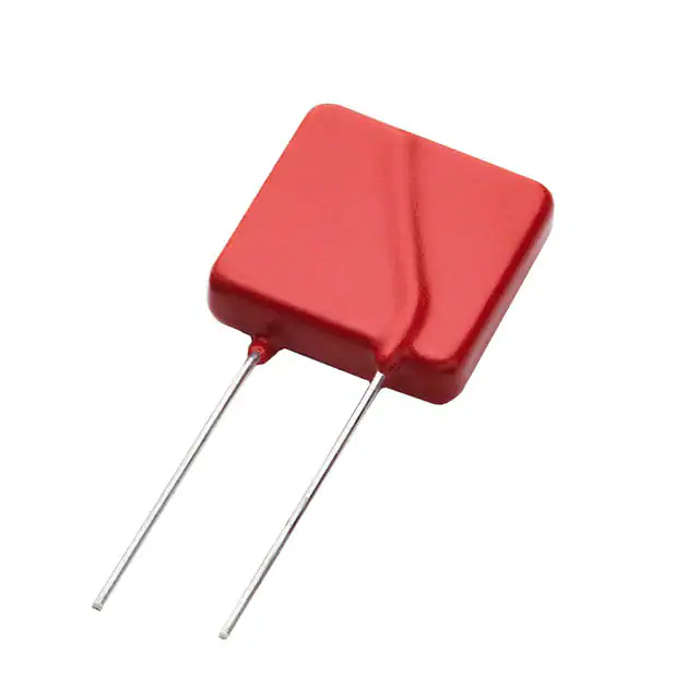
UltraMOV® 25S has compact square disc which is
made with radial wire leads. UltraMOV® 25S varistors
are manufactured with recognized epoxy encapsulation
and are rated for ambient temperatures up to 85°C
with no derating. This UltraMOV® 25S Series is
LASER-branded and is supplied in bulk packaging.
Features
• Lead–free, HalogenFree and RoHS
compliant
• 125°C operating
temperature-phenolic
coating option
• High peak surge
current rating
(ITM) 22kA, single
8/20µs pulse.
• 10kA Nominal
Discharge Current (In)
as required by UL 1449
• 20kV/10kA (1.2/50 μs,
8/20 μs) combination
pulse as required
by Annex G of
IEC 62368-1
• Maximum continuous
operating voltage
(MCOV): 115Vac
- 750Vac
Absolute Maximum Ratings
• For ratings of individual members of a series, see Device Ratings and Specifications chart
Continuous
UltraMOV® 25S Varistor Series
Units
Steady State Applied Voltage:
AC Voltage Range (VM(AC)RMS)
115 to 750
V
DC Voltage Range (VM(DC))
150 to 970
V
22,000
A
Transients:
Peak Pulse Current (ITM) 8x20µs Current Wave Single Pulse
Single-Pulse Energy Capability (WTM) 2ms Current Wave
230 to 890
J
Operating Ambient Temperature Range (TA)
-40 to +85
ºC
Storage Temperature Range (TSTG)
-40 to +125
ºC
UltraMOVTM 25S Varistor Series
Ratings & Specifications
Maximum Rating (85°C)
Continuous
Part Number
Branding
AC Volts
DC Volts
VM(AC)RMS
VM(DC)
Specifications (25°C)
Transient
Peak Surge
Energy
Current
2ms
8 x 20µs
WTM
ITM
1 x Pulse
1 x Pulse
(J)
(A)
Maximum Clamping
Voltage at 100A,
8 x 20µs
UL 1449
Voltage
Protection
Rating
Typical Capacitance
f = 1MHz
VNOM
Max
VC
VPR
C
Varistor Voltage
at 1mA DC
Test Current
VNOM
Min
(V)
(V)
V25S115P
P25S115
115
150
230
22000
162
(V)
198
295
(V)
400
4500
(pF)
V25S130P
P25S130
130
170
255
22000
184.5
225.5
335
500
3900
V25S140P
P25S140
140
180
285
22000
198
242
355
500
3500
V25S150P
P25S150
150
200
300
22000
216
264
390
500
3200
V25S175P
P25S175
175
225
315
22000
243
297
450
600
2550
V25S230P
P25S230
230
300
400
22000
324
396
585
700
1900
V25S250P
P25S250
250
320
435
22000
351
429
640
800
1750
V25S275P
P25S275
275
350
470
22000
387
473
700
900
1610
V25S300P
P25S300
300
385
500
22000
423
517
765
1000
1450
V25S320P
P25S320
320
420
540
22000
459
561
825
1000
1350
V25S385P
P25S385
385
505
630
22000
558
682
1010
1200
1080
V25S420P
P25S420
420
560
655
22000
612
748
1100
1500
1000
900
V25S440P
P25S440
440
585
675
22000
643.5
786.5
1160
n/a
V25S460P
P25S460
460
615
690
22000
675
825
1220
n/a
870
V25S510P
P25S510
510
670
700
22000
738
902
1335
n/a
820
V25S550P
P25S550
550
745
765
22000
819
1001
1475
n/a
750
V25S625P
P25S625
625
825
800
22000
900
1100
1625
n/a
660
V25S750P
P25S750
750
970
890
22000
1080
1320
1950
n/a
550
Note: Average powder dissipation of transients should not exceed 1.5 watts.
Transient V-I Characteristics Curves
Peak Current, Energy and Power Derating Curve
Peak Pulse Current Test Waveform for Clamping Voltage
100
PER C EN T O F PEAK VAL U E
P E R C E N T O F R A TE D V A L U E
100
80
60
40
20
50
0
O1
0
55
Figure 1
50
60
70
80
90
100 110 120 130
AM BIEN T T EM PER AT U R E (ºC )
For applications exceeding 85ºC ambient temperature, the
peak surge current and energy ratings must be reduced as
shown above.
Figure 2
t
t1
T IM E
t2
01 = Virtual Origin of Wave
T = Time from 10% to 90% of Peak
T1 = Rise Time = 1.25 x T
T2 = Decay Time
Example - For an 8/20 µs Current Waveform:
8µs = T1 = Rise Time
20µs = T2 = Decay Time
© 2020 Littelfuse, Inc.
Specifications are subject to change without notice.
Revised: GD. 12/23/20
�Metal-Oxide Varistors (MOVs)
Radial Lead Varistors > UltraMOVTM 25S Varistor Series
Transient V-I Characteristic Curve
10000
M a xim u m P e a k Vo lta g e (V )
625
440
420
385
550
510
460
750
1000
115
100
0.0 0 0 0 1
0.0 0 0 1
0.0 0 1
0.0 1
Figure 3
130
0.1
140
150
175
1
10
250
230
100
275
300
1000
320
10000
100000
P e a k C u rre n t (A )
Pulse Rating Curve
100000
1
2
15
10000
Peak Current (A)
1 02
1 03
1000
1 04
1 05
1 06
100
∞
10
1
Figure 4
10
100
1000
10000
Impulse Duration (µs)
Note: Repetitive surge capability is qualified and tested based on 8/20us current waveform (not combination waveform) and UL1449 40.7.3
(Edition 4) test condition.
© 2020 Littelfuse, Inc.
Specifications are subject to change without notice.
Revised: GD. 12/23/20
�Metal-Oxide Varistors (MOVs)
Radial Lead Varistors > UltraMOVTM 25S Varistor Series
Wave Solder Profile
Non Lead–free Wave Solder Profile
Lead–free Wave Solder Profile
300
300
250
TEMPERATURE (ºC)
TEMPERATURE (ºC)
Maximum Wave 260C
Maximum Wave 240C
250
200
150
100
50
200
150
100
50
0
0
0
0.5
1
1.5
Figure 5
2
2.5
3
3.5
4
TIME(MINUTES)
Physical Specifications
0
0.5
1
1.5
Figure 6
2
2.5
3
Copper Clad Steel Wire
Operating Temperature
-40°C to +85°C
Soldering Characteristics
Solderability per MIL–STD–202, Method 208
Cured, flame retardant epoxy polymer meets
UL94V–0 requirements
Marked with LF, voltage, UL/CSA Logos, and
date code
Storage Temperature
Solvent Resistance
-40°C to +125°C
+85°C, 85% RH, 1000 hours
+/-10% typical voltage change
+85°C to -40°C 5 times
+/-10% typical voltage change
MIL–STD–202, Method 215
Moisture Sensitivity
Level 1, J-STD-020
Device Labeling
4
Environmental Specifications
Lead Material
Insulating Material
3.5
TIME(MINUTES)
Humidity Aging
Thermal Shock
UltraMOV® 25S Varistor Series for High-Temperature Operating Conditions:
Phenolic coated devices are available with improved maximum operating temperature 125ºC.
These devices also have improved temperature cycling capability. Ratings and specifications
are per standard series except Hi–Pot Encapsulation (Isolation Voltage Capability) = 500V.
To order: add 'X1347' to part number (e.g. V25S150PX1347). These devices are NOT UL, CSA,
CECC or VDE certified.Contact factory for further details.
© 2020 Littelfuse, Inc.
Specifications are subject to change without notice.
Revised: GD. 12/23/20
�Metal-Oxide Varistors (MOVs)
Radial Lead Varistors > UltraMOVTM 25S Varistor Series
Product Dimensions (mm)
D
A max
b min
b max
D max
e min
e max
L
A
V25S115P
b
E
e1
e
e1 min
e1 max
E max
1.5
2.7
5.7
V25S130P
1.6
2.9
5.9
V25S140P
1.7
3.0
6.0
V25S150P
1.8
3.1
6.1
V25S175P
1.9
3.3
6.3
V25S230P
2.0
3.4
6.4
V25S250P
2.1
3.5
6.5
V25S275P
2.3
3.7
6.7
V25S300P
2.4
3.9
6.9
2.6
4.1
7.1
V25S320P
30.5
0.95
1.05
26.5
11.7
13.7
V25S385P
3.0
4.7
7.7
V25S420P
3.3
5.0
8.0
V25S440P
3.4
5.2
8.2
V25S460P
3.6
5.4
8.4
V25S510P
1.6
3.4
8.7
V25S550P
1.9
3.9
9.2
V25S625P
2.3
4.3
9.6
V25S750P
3.1
5.4
10.7
L min
25.4
Notes
1. Additional optional lead form, packaging and lead spacing requirements are subject to availability and to minimum
order requirements. Please contact factory for details.
2. Nickel Barrier Wire option (Suffix 'X2855')Standard parts use Tin-Coated Copper wire. Nickel Barrier Coated Wire
is available as an option. This is Copper Wire with a flashing of Nickel, followed by a top coat of Tin. To order please
add suffix 'X2855' to end of standard part number. Contact factory for more details if required.
Disclaimer Notice - Information furnished is believed to be accurate and reliable. However, users should independently evaluate the suitability of and test each product selected for their own applications. Littelfuse products are
not designed for, and may not be used in, all applications. Read complete Disclaimer Notice at www.littelfuse.com/disclaimer-electronics.
© 2020 Littelfuse, Inc.
Specifications are subject to change without notice.
Revised: GD. 12/23/20
�