MS4515
SPECIFICATIONS
Pressure Ranges from 2 to 30 inches H2O
Differential & Gage
.
PCB Mounted Pressure Transducers
Amplified Ratiometric Analog Output
Temperature Compensated
3.3V or 5.0 VDC Supply Voltage
FEATURES
Inches H2O Pressure Ranges
PCB Mountable
High Level Analog Output
Barbed Pressure Ports
APPLICATIONS
Blocked Filter Detection
Altitude and Airspeed
Measurements
Medical Instruments
Fire Suppression System
Panel Meter
Air Movement/Environmental
Controls
Pneumatic Controls
SENSOR SOLUTIONS /// MS4515
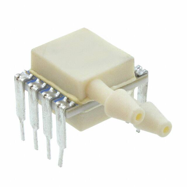
The MS4515 is a small, ceramic based, PCB mounted
pressure transducer from TE Connectivity. The transducer is built
using the latest CMOS sensor conditioning circuitry to create a low
cost, high performance transducer designed to meet the strictest
requirements from OEM customers.
The MS4515 is fully calibrated and temperature compensated with
a total error band (TEB) of less than 1.0% over the compensated
range. The sensor operates from single supply of either 3.3 or
5.0VDC and requires a single external component for proper
operation.
The rugged ceramic transducer is available in side port, top port,
and manifold mount versions and can measure gage or differential
pressure from 2 to 30 inches H2O. The 1/8” barbed pressure ports
mate securely with 3/32” ID tubing.
04/2019
Page 1
�MS4515
STANDARD RANGES (INCHES H2O)
Range
2
4
5
10
20
30
Gage
DS, SS, TP, MM
DS, SS, TP, MM
DS, SS, TP, MM
DS, SS, TP, MM
DS, SS, TP, MM
Differential
DS, SS, TP, MM
DS, SS, TP, MM
DS, SS, TP, MM
DS, SS, TP, MM
DS, SS, TP, MM
DS, SS, TP, MM
Option Availability
-F
-F
-F
See Package Configurations: DS= Dual Side Port, SS= Single Side Port, TP= Top Port, MM= Manifold Mount
Pin Style “L” is only available SS and MM port types.
Pin Style “C” is only available SS, TP and MM port types.
BLOCK DIAGRAM
SENSOR SOLUTIONS /// MS4515
04/2019
Page 2
�MS4515
ABSOLUTE MAXIMUM RATINGS
Parameter
Supply Voltage
Output Current
Load Resistance (RL)
Storage Temperature
Humidity
Overpressure
Burst Pressure
ESD
Solder Temperature
Conditions
TA = 25 °C
TA = 25°C
TA = 25°C
Min
2.7
Max
5.5
3
Unit
V
mA
kΩ
°C
%RH
psi
psi
kV
10
-40
+125
95
Not to Exceed 300
TA = 25°C
TA = 25 °C, both Ports
TA = 25 °C, Port 1
HBM
-4
+4
250°C, 5 sec max.
Notes
Non Condensing
See Table 1
EN 61000-4-2
TABLE 1- BURST PRESSURE BY RANGE AND PACKAGE STYLE
Style
DS, MM
Port
SS, TP
Port 1
Port 2
Port 1
002
10
10
004
10
10
10
005
10
10
10
010
10
10
10
020
10
10
10
030
20
20
20
Unit
PSI
PSI
PSI
ENVIRONMENTAL SPECIFICATIONS
Parameter
Mechanical Shock
Mechanical Vibration
Thermal Shock
Life
MTTF
SENSOR SOLUTIONS /// MS4515
Conditions
Mil Spec 202F, Method 213B, Condition C, 3 Drops
Mil Spec 202F, Method 214A, Condition 1E, 1Hr Each Axis
100 Cycles over Storage Temperature, 30 minute dwell
1 Million FS Cycles
>10Yrs, 70 ºC, 1.188 Million Pressure Cycles, 120%FS
Pressure
04/2019
Page 3
�MS4515
PERFORMANCE SPECIFICATIONS
Supply Voltage1: 5.0V or 3.3 VDC
Ambient Temperature: 25°C (unless otherwise specified)
PARAMETERS
Output
MAX
UNITS
0.500
MIN
TYP
4.500
V
0.250
4.75
V
NOTES
1,2,3
Accuracy
-0.25
0.25
%Span
2
Total Error Band (TEB)
-1.0
1.0
%Span
3,5
TEB (4inH2O and Below)
-2.0
2.0
%Span
3,5
mA
5
4
Supply Current
3
Compensated Temperature
0
+60
ºC
Operating Temperature
-10
+85
ºC
Response Time
1
Start time to data ready
Weight
Media
ms
6
3
5
ms
grams
Non-Corrosive Dry Gases Compatible with Ceramic, Silicon,
Borosilicate Glass, RTV, Gold, Aluminum and Epoxy. See “Wetted
Material by Port Designation” chart below.
Notes
1. Proper operation requires an external capacitor placed as shown in Connection Diagram. Output is ratiometric to supply voltage
variations of less than 10%.
2. Accuracy: The maximum deviation from a best fit straight line (BFSL) fitted to the output measured over the pressure range at 25°C.
Includes all errors due to pressure non linearity, hysteresis, and non-repeatability.
3. Total error band includes all accuracy errors, thermal errors over the compensated temperature range, and span and offset calibration
tolerances. For ideal sensor output with respect to input pressure, reference Pressure Transfer Function charts below. TEB values are
valid only at the calibrated supply voltage.
4. For errors beyond the compensated temperature range, see Extended Temperature Multiplier chart below.
5. This product can be configured for custom OEM requirements, contact factory for lower power consumption or higher accuracy.
CONNECTION DIAGRAM
Notes
1.
Place 100nF capacitor between Supply and GND to within 2 cm of sensor.
SENSOR SOLUTIONS /// MS4515
04/2019
Page 4
�MS4515
PRESSURE AND TEMPERATURE TRANSFER FUNCTION
Sensor Output at Significant Percentages, (Vs=5.00)
OUTPUT (%Vs)
0
5
10
50
90
95
100
Output Type A (inH20)
PMIN-(PMAX-PMIN)*10/80
Output Type B (inH20)
PMIN-(PMAX-PMIN)*5/90
PMIN
PMIN
PMAX
PMAX+(PMAX-PMIN)*10/80
PMAX
PMAX+(PMAX-PMIN)*5/90
Voltage (V)
0.000
0.250
0.500
2.500
4.500
4.750
5.000
Sensor Output at Significant Percentages, (Vs=3.30)
Output (%Vs)
0
5
10
50
90
95
100
SENSOR SOLUTIONS /// MS4515
Output A ( inH20)
PMIN-(PMAX-PMIN)*10/80
Output B ( inH20)
PMIN-(PMAX-PMIN)*5/90
PMIN
PMIN
PMAX
PMAX+(PMAX-PMIN)*10/80
PMAX
PMAX+(PMAX-PMIN)*5/90
04/2019
Voltage (V)
0.000
0.165
0.330
1.650
2.970
3.315
3.300
Page 5
�MS4515
EXTENDED TEMPERATURE MULTIPLIER CHART
2.5
2.0
1.5
1.0
0.5
0.0
-10
0
10
20
30
40
50
60
70
80
90
PACKAGE, PINOUT & PRESSURE TYPE CONFIGURATION
SENSOR SOLUTIONS /// MS4515
04/2019
Page 6
�MS4515
Prange is equal to the maximum full scale pressure specified in the ordering information.
Pin Name
SUPPLY
OUTPUT
GND
Pin
2
3
4
1, 5-8
Function
Positive Supply Voltage
Analog Output
Ground
No Connection
Pressure Type
Differential/
Bidirectional
Pmin
-Prange
Pmax
+Prange
Gage
0psiG
+Prange
Description
Output is proportional to the difference between Port 1 and Port 2. Output
swings positive when Port 1> Port 2. Output is 50% of supply voltage when Port
1=Port 2
Output is proportional to the difference between 0psiG (P min) and Port 1.
Output swings positive when Port 1> Port 2.
WETTED MATERIAL BY PORT DESIGNATION
Style
DS, MM
SS, TP,SM
Port
Port 1
Port 2
Port 1
Ceramic
X
X
X
Silicon
X
X
X
Material
Borosilicate Glass
X
X
X
RTV
X
X
X
Gold
Aluminum
X
X
X
X
Epoxy
X
X
X
"X" Indicates Wetted Material
SENSOR SOLUTIONS /// MS4515
04/2019
Page 7
�MS4515
DIMENSIONS (are in INCHES [mm])
Model: MS4515-DSvoxxxyP
Model: MS4515-DSvoxxxyS
SENSOR SOLUTIONS /// MS4515
04/2019
Page 8
�MS4515
Model: MS4515-SSvoxxxyP
Model: MS4515-SSvoxxxyS
SENSOR SOLUTIONS /// MS4515
04/2019
Page 9
�MS4515
Model: MS4515-TPvoxxxyP
Model: MS4515-TPvoxxxyS
SENSOR SOLUTIONS /// MS4515
04/2019
Page 10
�MS4515
Model: MS4515-SSvoxxxyL
Model: MS4515-MMvoxxxyL
SENSOR SOLUTIONS /// MS4515
04/2019
Page 11
�MS4515
Model: MS4515-MMvoxxxyP
Model: MS4515-MMvoxxxyS
SENSOR SOLUTIONS /// MS4515
04/2019
Page 12
�MS4515
Model: MS4515-SSvoxxxyC
Model: MS4515-TPvoxxxyC
SENSOR SOLUTIONS /// MS4515
04/2019
Page 13
�MS4515
Model: MS4515-MMvoxxxyC
AVAILABLE OPTIONS
Gel Coat (-F Option)
The MS4515 is designed for non-ionic and clean dry air applications. Select this option for added protection in
high humidity or slightly corrosive environments with the application of a silicone gel elastomer to sensor and
ASIC. For questions concerning media compatibility, contact the factory.
SENSOR SOLUTIONS /// MS4515
04/2019
Page 14
�MS4515
ORDERING INFORMATION
4515 – DS 3 A 030 D P F
Electrical
Single Sideport
SS
Dual Sideport
DS
Top Port
TP
MM
Manifold Mount
Option Type
[Blank]
No Option
F*
Gel Coating
*Options available for pressure ranges ≥10inH2O
Supply Voltage
3
3.3 VDC
5
5.0 VDC
Fitting Type
P
Thru Hole
S
J Lead
L
In Line
C
Castellation
Output Type
10% - 90%
A
5% to 95%
B
Pressure Type
Pressure Range [inH2O]
D
Differential
002
004
005
010
020
030
G
Gauge
NORTH AMERICA
EUROPE
ASIA
Measurement Specialties, Inc.,
a TE Connectivity company
Tel: 800-522-6752
Email: customercare.frmt@te.com
Measurement Specialties (Europe), Ltd.,
a TE Connectivity Company
Tel: 800-440-5100
Email: customercare.bevx@te.com
Measurement Specialties (China) Ltd.,
a TE Connectivity company
Tel: 0400-820-6015
Email: customercare.shzn@te.com
TE.com/sensorsolutions
Measurement Specialties, Inc., a TE Connectivity company.
Measurement Specialties, TE Connectivity, TE Connectivity (logo) and EVERY CONNECTION COUNTS are trademarks. All other logos, products and/or company names referred to herein
might be trademarks of their respective owners.
The information given herein, including drawings, illustrations and schematics which are intended for illustration purposes only, is believed to be reliable. However, TE Connectivity makes
no warranties as to its accuracy or completeness and disclaims any liability in connection with its use. TE Connectivity‘s obligations shall only be as set forth in TE Connectivity‘s Standard
Terms and Conditions of Sale for this product and in no case will TE Connectivity be liable for any incidental, indirect or consequential damages arising out of the sale, resale, use or misuse
of the product. Users of TE Connectivity products should make their own evaluation to determine the suitability of each such product for the specific application.
© 2015
TE Connectivity Ltd. family of companies
SENSOR SOLUTIONS /// MS4515
All Rights Reserved.
04/2019
Page 15
�


 工商网监
湘ICP备2023018690号
工商网监
湘ICP备2023018690号

