Instruction Sheet
408-- 8452
7000 Series 4- Pole Timing Relay
14 MAR 11
1. INTRODUCTION
Model 7024
This instruction sheet covers the installation and
operation of the AGASTAT* 7000 Series 4--Pole
Timing Relays (Models 7014 and 7024). Read these
instructions thoroughly before installing the relay.
NOTE
Rev A
Dimensions in this instruction sheet are in
millimeters [with inches in brackets]. Figures are
not drawn to scale.
L1
L2
1
2
3
5
TD
on
Drop-Out
4
8
7
2. DESCRIPTION (Figure 1)
Each relay is a precise timing instrument which
balances pneumatic, electrical, and mechanical forces
using a minimum of moving parts. When satisfactory
performance cannot be restored, the unit should be
returned to TE Connectivity for repair.
11
9
10
Energized
Contacts
N.C. (1-- 5)(2-- 6)
Model 7014
L1
L2
1
2
3
5
7
11
9
TD
on
Pick-Up
4
6
12
Delay Setting
Coil
N.C. (3-- 5)(4-- 6)
Contacts
N.O. (1-- 5)(2-- 6)
N.C. (9-- 11)(10-- 12)
Contacts
N.O. (7-- 11)(8-- 12)
De-- Energized
Open
Closed
N.O. (3-- 5)(4-- 6)
Open
Closed
Contacts
N.C. (7-- 11)(8-- 12)
Open
Closed
N.O. (9-- 11)(10-- 12)
Open
Closed
LINEAR TIMING RANGES
8
10
12
Delay Setting
Coil
4--Pole Timing Relay
(Typ)
6
Energized
De-- Energized
Closed
Open
Closed
Open
Closed
Open
Closed
Open
TIME RANGE
CODE
MODEL 7014D
MODEL 7024
A
0.2 to 2 Seconds
0.1 to 1 Second
B
0.7 to 7 Seconds
0.5 to 5 Seconds
C
2 to 20 Seconds
1.5 to 15 Seconds
D
10 to 100 Seconds
5 to 50 Seconds
E
30 to 300 Seconds
20 to 200 Seconds
F
1.5 to 15 Minutes
1 to 10 Minutes
H
3 to 30 Minutes
3 to 30 Minutes
I
Not Available
6 to 60 Minutes
J
Not Available
3 to 120 Cycles
K
Not Available
1 to 300 Cycles
D Model 7014 is available with letter calibrated dials only. The upper
end of the time ranges in this model may be twice the values shown.
Figure 1 (cont’d)
E2011 Tyco Electronics Corporation, a TE Connectivity Ltd. Company TOOLING ASSISTANCE CENTER 1--800--722--1111
All Rights Reserved
PRODUCT INFORMATION 1--800--522--6752
TE logo is a trademark.
*Trademark. Other product names, logos, or company names might be trademarks of their respective owners.
This controlled document is subject to change.
For latest revision and Regional Customer Service,
visit our website at www.te.com
1 of 2
LOC B
�408- 8452
AC COIL UNITS
DC COIL UNITS
CODE
LETTER
RATED
VOLTAGE
AT 60 Hz
RATED
VOLTAGE
AT 50 Hz
CODE
LETTER
RATED
VOLTAGE
A
120
110
M
28
B
240
220
N
48
C
480
--
O
24
D
550
--
P
120
E
24
--
Q
12
F
--
127
R
60
G
--
240
S
250
H
12
--
T
550
I
6
--
U
16
J
208
--
V
32
W
96
Y
6
Z
220
Dual Voltage Coil
(Combines A and B)
K
AC Specials L1, L2, etc.
DC Specials X1, X2, etc.
3. MOUNTING INSTRUCTIONS (Figure 2)
Normal mounting of the relay is in a vertical position,
from the back of the panel. Four No. 8--32 tapped
holes are provided in the back plate.
Mounting screws should not project more than
3.63 mm [5/32 in.] into the back of the unit, to
prevent internal damage.
CAUTION
A bracket and required screws are supplied with each
unit for mounting the unit from the front. The bracket
extends approximately 9.52 mm [3/8 in.] from each
side of the unit.
Horizontal operation is not recommended.
NOTE
Models 7014 and 7024 (Mounting Dimensions)
82.5 [3.25]
9.6 [.38]
73.2 [2.88]
44.4
[1.75]
5.1 [.199] Dia
Mtg Holes
12.7
[.50]
Operational voltage range 90% to 120% for AC units: 85% to 120%
for DC units.
All units draw approximately 8 watts power at rated voltage.
Minimum operating voltages are based on vertically mounted Model
7014 (on--delay) units.
38.1
[1.50]
AC units drop out at approximately 50% of rated voltage. DC units
drop out at approximately 40% of rated voltage.
All units may be operated on intermittent duty cycle at voltages 10%
above the listed maximums. (Intermittent duty -- maximum 50% duty
cycle and 30 minutes “on” time.)
63.5
[2.50]
19.0
[.75]
8-- 32 Mtg
Holes (4)
76.2
[3.00]
147.8
[5.82]
Max.
Coils are rated 6 Vac through 550 Vac.
CONTACT RATINGS
(Contact Capacity in Amperes - Resistive Loads)
CONTACT
VOLTAGE
MINIMUM 100,000
OPERATIONS
MINIMUM 1,000,000
OPERATIONS
30 Vdc
15.0
7.0
110 Vdc
1.0
0.5
120 Vac 60 Hz
20.0
15.0
240 Vac 60 Hz
20.0
15.0
480 Vac 60 Hz
12.0
10.0
Inductive and capacitive loads should not have inrush currents that
exceed five times normal operating load.
Contact ratings are listed under the Underwriters Laboratories Inc.
Component Recognition Program for 100,000 operations:
10 A Resistive, 240 Vac (per pole)
1/4 Horsepower, 120 Vac/240Vac (per pole)
15 A, 30 Vdc (per pole)
5 A, General Purpose, 600 Vac
Total load must not exceed twice the above listings per pole rating.
Continuous duty rating is 25 amperes any voltage, any load.
Figure 1 (end)
2 of 2
65.3
[2.57]
Max.
84.3
[3.32]
Max.
Figure 2
4. QUALIFICATIONS
The 7000 Series Timing Relays are Listed by
Underwriters Laboratories Inc. (UL) in File E15631.
and Certified to CSA International in File LR29186.
5. REVISION SUMMARY
S Updated document to corporate requirements
S New logo
Rev A
�
很抱歉,暂时无法提供与“7024AB”相匹配的价格&库存,您可以联系我们找货
免费人工找货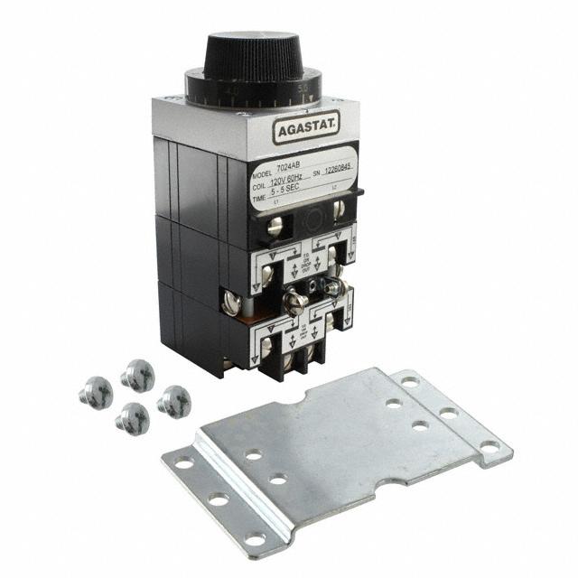


 工商网监
湘ICP备2023018690号
工商网监
湘ICP备2023018690号
