Spec No.J(E)TE243B-0022F
Reference Only
納入仕様書 Specifications
型名
1/12
FDUE1260
Type
外形寸法 Physical Dimensions
Marking refer to Next Page
Lot No.
公差 Tolerance : ±0.3
単位 Unit : mm
インダクタンス表示
Inductance ID
公称インダクタンス値を 3 文字で表す。The nominal inductance value is identified by three digits.
1) 3 桁数字の場合、最初の 2 桁の数字は公称インダクタンス値の有効数 2 桁を表し、
3 桁目の数字は 単位を μH とした場合の 有効数 2 桁に続く 零 の数を表す。
Three digits ID,First 2 digits indicate the effective inductance value
The last digit indicates the number of "0"following first 2 digits.The unit is μH.
2) R と 2つの数字で表す場合、単位を μH とし公称インダクタンス値の
小数点の位置をRにて示し、2つの数字と組み合わせて表す。
2 digits and letter "R" ID,The unit is μH. Letter "R"represent the decimal point.
優先言語
Priority language
優先言語は日本語とする。
Let a priority language be japanese.
�Reference Only
2/12
部品番号
品番
Customer's Part No.
Part No.
FDUE1260-H-R45N=P3
インダクタンス
Inductance
公称値 許容差
Center Tolerance
Value
測定
周波数
直流抵抗
Test
Freq.
(μH)
(%)
(kHz)
DC
Resistance
±7%
(mΩ)
0.45
±30
100
0.58
定格電流
定格電流
(インダクタンス変化に (温度上昇に基づく
基づく場合)
場合)
Rated Current
Rated Current
Based on
Based on
Inductance Change
Temperature rise
(A) (Max.)
(A) (Max.)
32
(1)インダクタンス
Inductance
: LCRメータ 4284A(アジレント)または同等品により測定。(測定周波数 100kHz 、レベル 0.5V)
: Measured with a LCR meter 4284A(Agilent) or equivalent.(Test Freq. 100kHz、Level 0.5V)
(2)直流抵抗
DC Resistance
: マイクロΩメータ 34420A(アジレント)または3541(HIOKI)と同等品により測定。
直流抵抗の測定箇所は側面です。(Picture-1を参照願います。)
: Measured with a Micro ohm meter 34420A(Agilent) or 3541(HIOKI) or equivalent.
The measurement point of DCR is side of terminal. (refer to the Picture-1)
(3)定格電流
Rated Current
・定格電流
34
Picture-1
: 定格電流(インダクタンス変化に基づく場合)又は定格電流(温度上昇に基づく場合)の
何れか小さい方の直流電流値とします。
: Value defined when DC current flows and Rated Current (Based on Inductance Change)
or when current flows and Rated Current (Based on Temperature rise) whichever is smaller.
: 定格電流(インダクタンス変化に基づく場合)とはインダクタンスが初期値より30% 低下した時の電流値。
: The DC saturation allowable current value is specified when the decrease of the
nominal inductance value at 30%.
(Based on Inductance Change)
・定格電流
(温度上昇に基づく場合)
・Rated Current
: 定格電流(温度上昇に基づく場合)とは、試験基板に実装したインダクタに
直流を流した時の製品温度上昇が 40℃ に達する電流値。
: Rated Current (Based on Temperature rise) is specified when temperature of the
inductor on our PCB for test purpose is raised 40℃ by DC current.
(Based on Temperature rise)
(4)絶対最大電圧
: 絶対最大電圧は30V DC です。
Absolute maximum voltage : Absolute maximum voltage 30V DC.
Inductance
marking
R45
測定箇所
measurement point
(インダクタンス変化に基づく場合)
・Rated Current
インダクタンス
表示
*特に指定がない限り、測定は標準状態で行う。
Unless otherwise specified, measurement is the standard atmospheric conditions.
Spec No.J(E)TE243B-0022F
FDUE1260 Type 電気的個別性能 Electrical specifications
�Spec No.J(E)TE243B-0022F
Reference Only
FDUE1260 Type 一般仕様 General Specifications ( 1/3 )
項 目 Item
1 たわみ強度
Bending test
規 格 Specification
条 件 Condition
初期値に対する
Lの変化率 ± 5%以内
矢印の方向に曲げ幅 2mmになるまで毎秒約 0.5mmの速さで
加圧し 30±5秒間保持する。
Change from an initial value
L : within ± 5%
Apply pressure gradually in the direction of the arrow at a rate of about
0.5mm/s until bent depth reaches 2mm and hold for 30±5 s.
基板 Board : 40 × 100mm
厚さ thickness 1.0mm
2 固着強度
Adhesion strength
3 耐振性
Vibration
4 耐衝撃性
Mechanical shock
5 自由落下試験
Free fall test
6 はんだ付け性
Solderability
7 はんだ耐熱性
Resistance to
soldering heat
初期値に対する
Lの変化率 ± 5%以内
R0.5の押し治具を使用して、矢印の方向に
静荷重を加え60±5秒間保持する。
測定は、荷重を取り去った後に行なう。
Change from an initial value
L : within ± 5%
A static load using a R0.5 pressing tool shall be applied
to the body of the specimen in the direction of the arrow and
shall be hold for 60±5 s. Measure after removing pressure.
初期値に対する
Lの変化率 ± 5%以内
掃引の割合 10~55~10Hz/分、全振幅 1.5mm
X・Y・Z 方向に各 2時間(計 6時間)加える。
Change from an initial value
L : within ± 5%
The specimen shall be subjected to a vibration of 1.5mm
amplitude, sweep frequency 10~55Hz(10Hz to 55Hz to 10Hz
in a period of one minute) for 2 h in each of 3(X, Y, Z) axes.
初期値に対する
Lの変化率 ± 5%以内
加速度 Peak acceleration
作用時間 Duration of pulse
3方向に各 3回(計 9回)
: 981 m/s2
: 6 ms
: 3 times in each of 3(X, Y, Z) axes.
Change from an initial value
L : within ± 5%
Three successive shock shall be applied in the perpendicular
direction of each surface of the specimen.
初期値に対する
Lの変化率 ± 5%以内
供試品を取り付けた試験基板を、質量 200g の治具に
取り付け,高さ 1m から堅い木版上に、互いに垂直
な3方向に、各3回(計 9回)自然落下させる。
Change from an initial value
L : within ± 5%
The specimen must be fixed on test board. It must be equipped with
instruments of which weight is 200g. Then it shall be fallen freely
from 1m height to rigid wood 3 times in each of three axes.
浸漬した電極面の 90%
以上新しいはんだで覆わ
れている事。
New solder shall cover
90% minimum of the surface
immersed.
電極に常温にてフラックスを塗布し下記条件にて
プリヒート後試料全体をはんだ槽に浸漬する。
Electrode shall be immersed in flux at room temperature
and then shall be immersed in solder bath after preheat.
・はんだ付け Soldering
245±5℃ , 3±1s
初期値に対する
Lの変化率 ± 7%以内
試験方法 Test method
リフローはんだ Reflow soldering method
・プリヒート Preheat
150~180℃ , 90±30 s
・ピーク温度 Peak temp. 250(+5,-0)℃ ( 230℃min , 30±10 s )
試料を板厚0.8mmガラスエポキシ基板に置き、上記
条件にてリフロー炉を2回通す。
Change from an initial value
L : within ± 7%
The specimen shall be subjected to the reflow process
under the above condition 2 times.
Test board shall be 0.8 mm thick. Base material shall
be glass epoxy resin.
測定 Measurement
常温常湿中に1時間放置後測定。
The specimen shall be stored at standard atmospheric
conditions for 1 h in prior to the measurement.
3/12
�Reference Only
Spec No.J(E)TE243B-0022F
FDUE1260 Type 一般仕様 General Specifications ( 2/3 )
項 目 Item
8 耐電圧
Dielectric strength
9 耐寒性
Low temperature
規 格 Specification
異常がないこと。
端子・コア間に DC50V を 1分間印加。センス電流は5mA。
Without damage.
50V DC shall be applied for 60 s between the terminal and the core.
Cut off current 5mA.
初期値に対する
Lの変化率 ± 5%以内
温度-40±3℃中に 500±12時間放置後常温常湿中に
1時間放置し、1時間以内に測定。
Change from an initial value
L : within ± 5%
10 耐熱性
Dry heat
初期値に対する
Lの変化率 ± 5%以内
Change from an initial value
L : within ± 5%
11 耐湿性
Damp heat
初期値に対する
Lの変化率 ± 5%以内
Change from an initial value
L : within ± 5%
12 温度サイクル
Temperature cycle
13 温度特性
Temperature drift
14 使用温度範囲
Operating temperature
range
条 件 Condition
初期値に対する
Lの変化率 ± 5%以内
The specimen shall be stored at a temperature of -40±3℃
for 500±12 h. Then it shall be stabilized under standard
atmospheric conditions for 1 h before measurement.
Measurement shall be made within 1 h.
温度+125±2℃中に 500±12時間放置後常温常湿中に
1時間放置し、1時間以内に測定。
The specimen shall be stored at a temperature of 125±2℃
for 500±12 h. Then it shall be stabilized under standard
atmospheric conditions for 1 h before measurement.
Measurement shall be made within 1 h.
温度60±2℃、湿度90~95%中に 500±12時間放置後
常温常湿中に1時間放置し、1時間以内に測定。
The specimen shall be stored at a temperature of 60±2℃
with relative humidity of 90~95% for 500±12 h. Then it shall be
stabilized under standard atmospheric conditions for 1 h
before measurement. Measurement shall be made within 1 h.
-40℃(30分)→常温(2分以内)→125℃(30分)→常温
(2分以内)を1サイクルとし、これを 500サイクル行い、
常温常湿中に1時間放置し、1時間以内に測定。
Change from an initial value
L : within ± 5%
The specimen shall be subjected to 500 continuous cycles
of temperature change of -40℃ for 30 min and 125℃ for
30 min with the transit period of 2min or less. Then it shall be
stabilized under standard atmospheric conditions for 1 h
before measurement. Measurement shall be made within 1 h.
インダクタンス温度係数
560 ppm/℃ 以下
温度-40~+125℃の間で測定。
Inductance temperature coefficient
560 ppm/℃ or less
To be measured in the range of -40℃ to 125℃.
-40 ~ +125℃
自己温度上昇を含む。
Including self temperature rise.
4/12
�Spec No.J(E)TE243B-0022F
Reference Only
FDUE1260 Type 一般仕様 General Specifications ( 3/3 )
標準状態
Standard atmospheric conditions
特に指定が無い限り、測定は常温(温度 15~35℃)、常湿(湿度25~85%)にて行う。
ただし、判定に疑義を生じた場合は温度20±2℃、湿度60~70%、気圧86~106kPaにて行う。
Unless otherwise specified, the standard range of atmospheric conditions in making measurements and test as follows;
Ambient temperature : 15℃ to 35℃ , Relative humidity : 25% to 85%
If more strict measurement is required, measurement shall be made within following limits;
Ambient temperature : 20±2℃ ,
Relative humidity : 60% to 70% ,
Air pressure : 86kPa to 106kPa
リフローはんだ条件
Reflow soldering condition
*リフロー回数 : 2回まで
Reflow times : 2 times max
*リフロー炉の熱源には、遠赤外線を推奨致します。
熱源としてハロゲンランプを使用されますと、輻射熱が
高く、耐熱範囲を超える場合があり推奨できません。
We recommend infrared ray as heat source of reflow bath.
However halogen lamp shall be used, side heat will be beyond
range of resistance heat, so we can’t recommend it.
推奨パターン図
Recommended PCB pattern
ランド寸法設計 Land pattern designing (Reflow Soldering)
リフローはんだ付け時の標準ランド寸法を下記に示します。
標準ランド寸法は、電気特性、実装性を考慮して設計されています。この寸法以外で設計されますと、
これらの性能が十分発揮できないことがあります。場合によっては、位置ずれ等のはんだ付け不良と
なることがありますので、貴社にてご確認の上ご使用ください。
Recommended land pattern for reflow soldering is as follows:
It has been designed for Electric characteristics and solderability.
Please follow the recommended patterns. Otherwise, their performance which includes electrical performance or
solderability may be affected, or result to "position shift" in soldering process.
単位 Unit : mm
5/12
�Spec No.J(E)TE243B-0022F
Reference Only
6/12
FDUE1260 Type 梱包仕様 Packing Specifications
1. テープ寸法図 Tape dimensions
12.9
14.7
φ1.5
1.75
11.5
4.0
A
B
D0
E
F
P0
引き出し方向
Unreeling direction
±0.1
±0.1
+0.1
-0
±0.1
±0.1
P1
P2
T1
T2
W
16.0
2.0
0.4
6.37
24.0
±0.1
±0.05
±0.1
±0.3
±0.1
・装着テープ材質 Carrier tape material
ポリスチレン Polystyrene
・シールテープ材質 Fixing seal tape material
ポリエチレン および ポリエチレンテレフタレート
Polyethylene and Polyethylene Terephthalate
・シールテープ剥離強度
The force to peel away the fixing seal tape
0.2~0.7N
2. テーピング方法 Taping method
Part No.●
Lot No.
( トップカバーテープ側からみる。 )
(The direction shall be seen from the top cover tape side. )
上面図(Top view)
引き出し方向
Unreeling direction
3. リール寸法図 Reel dimensions
A
B
C
D
E
F
G
φ330
25.5
29.5
φ80
φ13
φ21
2
±2
±0.5
±1
±1
±0.2
±0.8
±0.5
・リール材質 Reel material
ポリスチレン Polystyrene
・表示 Marking
貴社部品番号,数量,RoHS Comp.
Customer's part number, Quantity,RoHS Comp.
4. 数量 Quantity
個/リール
pieces/reel
5. 梱包箱 Packing case
500
・梱包箱材質 Packing case material
紙 Kraft paper
・収納数 Real quantity per packing case
1リール 1reel/1box
・表示 Marking
貴社部品番号,数量,RoHS Comp.
Customer's part number, Quantity, RoHS Comp.
�Spec No.J(E)TE243B-0022F
Reference Only
FDUE1260 Type 注意事項 Precautions
使用上の注意事項(安全対策) Notice
1, 樹脂コーティング Resin coating
製品を樹脂で外装される場合、樹脂のキュアストレスが強いとインダクタンスが変化したり製品の性能に
影響を及ぼすことがありますので、樹脂の選択には十分ご注意下さい。また、実装された状態での信頼性評
価を実施下さい。
The inductance value may change and/or it may affect on the product's performance due to high
cure-stress of resin to be used for coating / molding products. So please pay your careful attention whenyou select resin.
In prior to use, please make the reliability evaluation with the product mounted in your application set.
2, この商品は、従来形のコイルに比べ、絶縁抵抗が低いため、ご使用にあたり注意が必要です。
This product employs a core with low insulation resistance, Pay strict attention when use it.
a) コイルの下には電極部を除きスルーホールやパターンの設置をお避け下さい。
a) Do not make any through holes and copper pattern under the coil.
except a copper pattern to the electrode.
b) コイルに他の部品が触れない様にご設計をお願いします。
b) Design/mount any components not to contact this product.
3, フェールセーフ Fail-safe
当製品に万が一異常や不具合が生じた場合でも、二次災害防止のために完成品に適切な
フェールセーフ機能を必ず付加して下さい。
Be sure to provide an appropriate fail-safe function on your product to prevent a second damage that may be
caused by the abnormal function or the failure of our product.
4, 定格上の注意 Caution(Rating)
定格電流を超えてのご使用は避けてください。定格電流を超えて使用しますと、当製品は発熱し、
ワイヤー間のショート、断線あるいははんだが溶けて部品が脱落する恐れがあります。
Do not exceed maximum rated current of the product. Thermal stress may be transmitted to the product and
short/open circuit of the product or falling off the product may be occurred.
5, 温度上昇 Temperature Rise
コイルの温度はご設計環境で大きく変わります。
熱設計には充分ご注意をされ温度保証範囲でのご設計をお願いします。
Temperature rise of power choke coil depends on the installation condition in end products.
It shall be confirmed in the actual end product that temperature rise of power choke coil is in the limit
specified temperature class.
6, 洗浄について Cleaning
洗浄する場合は支障がないことをご確認の上ご使用ください。
If a washing process is applied,please make sure there is no problem with operating.
7, 標準はんだ付け条件 Standard Soldering Conditions
半田方式 リフローでご使用ください。
Please use reflow be soldering method.
使用フラックス、はんだ Flux, Solder
・ロジン系フラックスをご使用下さい。
・Use rosin-based flux.
フラックス ・酸性の強いもの[ハロゲン化物含有量0.2(wt)%(塩素換算値)を超えるもの]は
Flux
使用しないで下さい。
・Don’t use highly acidic flux with halide content exceeding 0.2(wt)% (chlorine conversion value).
・水溶性フラックスは使用しないで下さい。
・Don’t use water-soluble flux.
はんだ
・Sn-3.0Ag-0.5Cu 組成の無鉛はんだをご使用下さい。
Solder
・Use Sn-3.0Ag-0.5Cu solder
7/12
�Spec No.J(E)TE243B-0022F
Reference Only
FDUE1260 Type 注意事項 Precautions
実装上の取り扱い注意 Notice
8, 使用上の注意 Notice
本製品は、はんだ付けにて接合されることを意図して設計しておりますので、導電接着剤での接合等の方法を使用
される場合は事前に弊社にご相談ください。
This product is designed for solder mounting.
Please consult us in advance for applying other mounting method such as conductive adhesive.
8-1, 部品配置 Product's location
基板設計時、部品配置について次の点にご配慮下さい。
① 基板のそり・たわみに対して、ストレスが加わらないように部品を配置して下さい。
The following shall be considered when designing and laying out P.C.B.’s.
① P.C.B. shall be designed so that products are not subject to the mechanical stress due to warping the board.
[部品方向 Products direction]
a
b
〈Poor example 〉
〈Good example 〉
ストレスの作用する方向に対して、
横向き(長さ:a
很抱歉,暂时无法提供与“FDUE1260-H-R45N=P3”相匹配的价格&库存,您可以联系我们找货
免费人工找货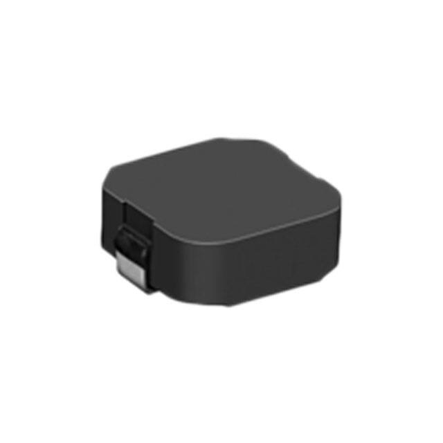


 工商网监
湘ICP备2023018690号
工商网监
湘ICP备2023018690号
