Radial Leaded Capacitors
Commercial Grade Capacitors – RDE 25/50/100VDC
RDE Product Summary
RDE Series:
The RDE, radial leaded,
epoxy coated monolithic ceramic capacitor
has been designed for commercial applications.
Murata Electronics North America, Inc. has
added a lineup of 25, 50 and 100VDC RDE
components in C0G, X7R, X7S and Y5V TC’s
to the existing 250 and 630VDC, X7R RDE
series. All RDE’s are RoHS compliant and
have an epoxy coating and tin/copper plated
radial leads. The commercial grade RDE’s
are designed for general use electronics
applications and not for automotive powertrain
and safety (ABS, Air Bag, etc) applications.
They are a cost effective alternative to our
automotive grade RPE series for noncritical
applications.
Features:
Case Size: 0, 1, 2, 3 and W (See dimensions table on back for details.)
B
� ody Size: The 0 & 1 size RDE products are the smallest leaded devices offered by Murata.
Lead Spacing: 2.5 +/- 0.8mm, 5.0 +/- 0.8mm
Voltage: 25, 50 and 100VDC
Cap Range: See “Capacitance Range” Chart on page 2
B
� ase Metal Inner Electrodes: Copper plating + Ni plating + Sn plated terminations
Body Coating: Epoxy coated body with Tin/Copper coated Radial Leads
��Tolerance: [J]=+/-5% for C0G, [K]=+/-10% for X7R and X7S and [Z]=+80/-20% for Y5V
T
� emp. Characteristics: C0G (-55 to 125°C, +/- 30ppm/°C), X7R (-55 to125°C, +/- 15%),
X7S (-55 to125°C, +/- 22%) and Y5V (-30 to 85°C, +22 /- 82%)
RDE Series
Applications: Commercial
Electronics, Consumer
Electronics, White Goods
w
w
w
.
m
u
r
a
t
a
.
c
o
m
�Radial Leaded Capacitors
Commercial Grade Capacitors – RDE 25/50/100VDC
RDE Data Sheet
L max.
L max.
T max.
max.
TT
max.
L max.
25.0min.
25.0min.
25.0min.
*
Dimensions
(mm
max)
Dimensions
(mm
max)
Dimensions
(mm
max)
T max.
Size
Code
W1 W1
Size
Code L L L
T
Size
Code
W1
TT
Dimensions
(mm max)
4.04.0 6.0
6.0 6.0 2.5
2.5 2.5
0 00
4.0
Size Code
L
W1
T
1 11
4.5
4.54.5 5.0
5.0 5.0 3.15
3.15 3.15
0
4.0
6.0
2.5
22
5.5
6.0
3.15
5.5
6.0
3.15
2
5.5
6.0
3.15
4.5
5.0
3.15
3 13
5.5
7.5
4.0
5.5
7.5
4.0
4.0
23
5.5 5.5 10.0
6.0 7.5 3.15
WW
5.5
4.0
5.5
10.0
4.0
3W
5.5 5.5
7.5 10.0 4.0
4.0
* Coating
Extension
does
not
exceed
the
end
ofof
the
* Coating
Extension
does
not
exceed
the
end
the
W
5.5 does10.0
lead
bend.
*lead
Coating
not exceed4.0
the end of the
bend.Extension
W1
max
25.0min.
** *
L max.W1
W1
W1
max
max
max
Structure
0.5+/-0.05
0.5+/-0.05
0.5+/-0.05
0.5+/-0.05
5.0+/-0.8
5.0+/-0.8
5.0+/-0.8
5.0+/-0.8
Capacitance
CapacitanceRange
Range
apacitance
Range
Size
Size
Capacitance
Range
TCTC
WV
WV
Code
10pF
SizeCode
10pF
SizeTC
TC WV
WV
50V
Code
50V
Code
10pF
00
C0G
10pF
C0G
Inner Solder
Solder
Outer Electrode
Copper plating
+ Ni plating
+ Sn plating
Dielectric
(Ceramic)
100pF
100pF
100V
50V
50V
C0G
1000pF
1000pF
100pF
100pF
0.01uF
0.01uF
1000pF
1000pF
0.01uF
0.01uF
Capacitance
CapacitanceRange
Range
0.1uF
1uFRange
Capacitance
0.1uF
Capacitance Range1uF
0.1uF 0.1uF
1uF
10uF
10uF
1uF10uF
100uF
100uF
10uF
100uF
3
0
2.2uF
100V
Y5V
pF
pF/ uF
/ uF
10pF
toto1000pF
(E12)
10pF
1000pF
(E12)
100uF
pF / uF
pF / uF
10pF
to
1000pF
(E12)
to 1000pF
(E12)
10pF10pF
to 1000pF
(E12)
10pF to
1000pF (E12)
0.1uF
0.1uF
10pF to 1000pF
(E12)to 1000pF (E12)
10pF
220pF
to 0.1uF
220pF
0.1uF to 0.1uF
0.1uF
0.15uF
to
0.15uF
to0.47uF
0.47uF
220pF
to 0.1uF
220pF
to 0.1uF
0.68uF
to 2.2uF
0.15uF
to 0.47uF
0.68uF
to 2.2uF
3.3uF
0.15uF to 0.47uF
0.68uF to3.3uF
2.2uF
1000pF
to 0.022uF
0.68uF to 2.2uF
3.3uF
1000pF
to 0.022uF
0.033uF
to 0.47uF
1000pF
to 0.022uF
3.3uF
0.033uF
to 0.47uF
0.033uF to1uF
0.47uF
1uF
1000pF to 0.022uF
0.22uF
1uF toto1uF
0.22uF
1uF
0.033uF
to 0.47uF
0.22uF 2.2uF
to2.2uF
1uF
1uF
4.7uF,
2.2uF 10uF
4.7uF, 10uF
4.7uF,22uF
10uF 0.22uF to 1uF
22uF
47uF
2.2uF
22uF
47uF
4.7uF 4.7uF, 10uF
47uF
4.7uF
2.2uF
4.7uF
22uF
2.2uF
4.7uF
2.2uF
47uF
4.7uF
4.7uFto 0.1uF
0.01uF
0.01uF to 0.1uF4.7uF
0.01uF to 0.1uF
RDE Series
25V
25V
100V
100V
00
0
25V
0 1
25V
1 0
50V
50V
0 2
2 1 X7R
X7R
50V
3
1 3 2
X7R 50V
0
2 0 3
X7R
100V
100V
3 11 0
2 1
100V
0 2
0 2
100V
1 0
1 0
1
2 2
25V
1
25V
2
0 3 2
25V
X7S
3
X7S
1W 3
X7S
W
50V
25V
2 2 W
2
50V
3
2
50V
3 3
100V
X7S
W 3
100V
100V
W W
0 W Y5V
50V
2 0 0
50V
Y5V
50V
Y5V
50V
W
Inner Electrode
Ni
Lead Wire
Sn/Cu solder
coated copper wire
or solder coated
CP wire
* Coating
Extension does not exceed the end of the
lead bend.
lead bend.
100V
0 0 0 0 C0G
Body Coating
Epoxy
Global Part Numbering
Global Part
PartNumbering
Numbering
Global
50V
4.7uF
0.01uF to 0.1uF
� �
�� ��
�Type Name
�
TypeName
Name
�
Type
Name Coated Material
Name Coated
CoatedMaterial
Material
Name
RDE
Epoxy Coating
RDE
RDE
EpoxyCoating
Coating
Epoxy
�Rated Voltage
�
Rated
Voltage
�
Rated
Voltage
�
Type
Name
Code
Rated
Voltage
Code Rated Voltage
Code Coated
Rated
Name
Material
1E
25VVoltage
1E
25V
25V
1H1E
50V
RDE
Coating
1H Epoxy50V
50V
2A1H
100V
2A
100V
2A
100V
�
Rated Voltage
�Capacitance
�Capacitance
Code
Rated Voltage
�
Capacitance
Capacitance
Step
Capacitance Step
1E
25V Step
SeeCapacitance
Part Number
List
See Part Number List
1HSee Part Number
50V List
�
Tolerance
2ACapacitance
100V
�Capacitance
Tolerance
�Capacitance
Tolerance
Code
Tolerance
Code
Tolerance
�Capacitance
J J
+/-5%
Code
Tolerance
+/-5%
KJK
+/-10%
Capacitance
Step
+/-5%
+/-10%
M KM
+/-20%
+/-10%
+/-20%
See
Number
List
Z MPart
+80/-20%
Z
+80/-20%
+/-20%
Global Part Numbering
�Temperature Characteristics
Temperature Characteristics
�Temperature
Characteristics
Code Temp. Char.
Operating Temp. Range
Capacitance Change
Range
Change
Code Temp.
Temp. Char.
Char. Operating
OperatingTemp.
Temp.
Range Capacitance
Capacitance
Change
5C
C0G
-55 to 125℃
0+/-30ppm/℃
�
�
5C
C0G
-55
toto125℃
125℃
0+/-30ppm/℃
5C
C0G
-55to
125℃
0+/-30ppm/℃
R7
X7R
-55
+15/-15%
R7
X7R
-55
toto125℃
125℃
+15/-15%
R7
X7R
-55to
125℃
+15/-15%
C7
X7S
-55
+22/-22%
C7Temperature
X7S
-55
125℃
+22/-22%
�
Characteristics
C7
X7S
-55to
125℃
+22/-22%
F5
Y5V
-30
toto85℃
+22/-82%
F5
Y5V
-30
+22/-82%
F5
Y5V Char.
-30toto85℃
85℃
Code
Temp.
Operating
Temp. Range +22/-82%
Capacitance Change
�Lead Configuration & Space
�Dimensions (L x W)
�
Lead
Configuration & Space0+/-30ppm/℃
�5C
Dimensions
(L x W)
C0G
-55
to 125℃
�
Lead
Configuration & Space
�
Dimensions (L x W)
Code Lead Configuration Lead Space
Code
L X7R
xW
R7
-55
to
125℃
+15/-15%
Code Lead Configuration Lead
Space
Code
LxW
Code Outside-crimp
Lead Configuration
Lead Space
Code
xW
P1
Bulk
F=2.5mm
0 C7
4.0 x L
6.0mm
X7S
-55
to
125℃
+22/-22%
P1
Outside-crimp Bulk
F=2.5mm
0
4.0 x 6.0mm
S1
Taping
F=2.5mm
P1 Outside-crimp
Outside-crimp
Bulk
F=2.5mm
1 F5
4.5
0
4.0x x5.0mm
6.0mm
-30 toOutside-crimp
85℃
+22/-82%
S1
Taping
F=2.5mm
1
4.5 xY5V
5.0mm
K1
Incrimp
Long
Bulk
F=5.0mm
S1
Outside-crimp
Taping
F=2.5mm
21
5.5
x
6.0mm
4.5 x 5.0mm
K1
Incrimp Long Bulk
F=5.0mm
2
5.5 x 6.0mm
M1
Incrimp Taping
F=5.0mm
K1
Long Bulk F=5.0mm
F=5.0mm
32
5.5
5.5x xx7.5mm
6.0mm
M1
Incrimp
Taping
3
5.5
7.5mm
�
Lead
Configuration
& Space
�
Dimensions (L x W)
W3
5.55.5
x 10.0mm
M1
Incrimp Taping
F=5.0mm
x
7.5mm
W
5.5 x 10.0mm
�
W
5.5 x 10.0mm
Code Lead Configuration Lead Space
�Packaging
Packaging
Code
LxW
�Packaging
Code
PackageOutside-crimp
Type Size Code
Std. F=2.5mm
Pack Qty.
�
Individual
Specification
P1
BulkStd.
Code Package
Type Size Code
Pack Qty.
�
Individual
Specification
0
4.0
x 6.0mm
Code
B
Bulk
0
3
500
pcs. Qty.
Code
Package
Type
Size
Code
Std.
Pack
Code
�Individual
Specification
S1 Bulk
Outside-crimp
B
0 - 3Taping 500F=2.5mm
pcs.
1
4.5
x 5.0mm
*1
Code
A
Ammo
Pack
0
3
2000
pcs.
-3
500
pcs.
A B K1
AmmoBulk
Pack
0 - 03 Bulk
2000F=5.0mm
pcs.*1
Incrimp Long
2
5.5 x 6.0mm
*1
*1 Confirm detail specifications
Confirm
detail
specifications
A M1
Ammo
Pack
0-3
2000
pcs.*1
Incrimp Taping
F=5.0mm
3
W
Z
+80/-20%
�Capacitance
Tolerance
Code
C-37-BJ
Tolerance
+/-5%
w
5.5 x 7.5mm
5.5 x 10.0mm
*1
Confirm detail specifications
�Packaging
�
w Individual
w . m Specification
u r a t a Code
. c Package
o m Type
Code
B
A
Bulk
Ammo Pack
Size Code
Std. Pack Qty.
0 - 3 Murata Electronics
500 pcs.
©2010
N.A., Inc.
0-3
2000 pcs.*1
�
很抱歉,暂时无法提供与“RDEC72A225K3M1C03A”相匹配的价格&库存,您可以联系我们找货
免费人工找货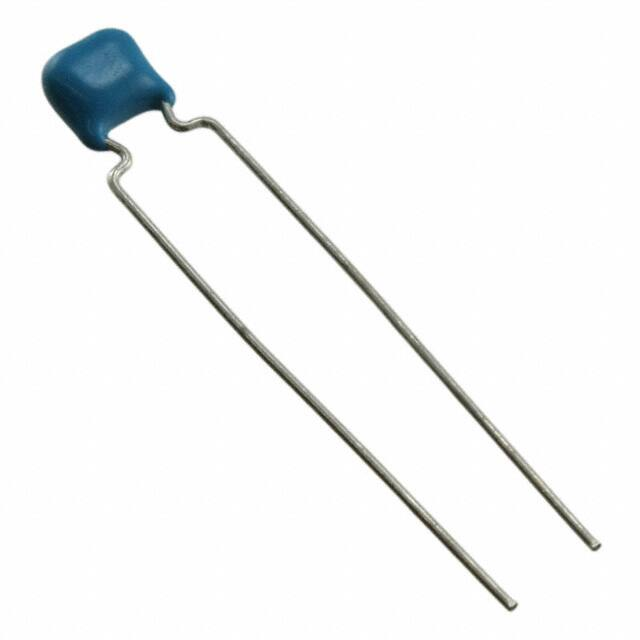


 工商网监
湘ICP备2023018690号
工商网监
湘ICP备2023018690号
