Miniature SOP4-pin type
with current limiting
GU SOP 1 Form A
Current Limiting (AQY210LS)
4.3
.169
4.4
.173
2.1
.083
mm inch
1
4
2
3
RoHS compliant
FEATURES
TYPICAL APPLICATIONS
1. Current limiting function
To control an over current from flowing,
the current limit function has been
realized. It keeps an output current at a
constant value when the current reaches
a specified current limit value.
2. Enhances the capability of surge
resistance between output terminals
The current limit function controls the ON
time surge current to enhance the
capability of surge resistance between
output terminals.
3. Small SOP4-Pin package
The device comes in a super-miniature
SO package 4-Pin type measuring (W)
4.3×(L) 4.4×(H) 2.1 mm (W) .169×(L)
.173×(H) .083 inch
4. Controls low-level analog signals
5. Low-level off state leakage current
• Telephone equipment
• Modem
• Measuring equipment
TYPES
Output rating*
AC/DC
dual use
Part No.
Load
voltage
Load
current
Package
350V
120mA
SOP4-pin
Tube packing style
AQY210LS
Packing quantity
Tape and reel packing style
Picked from the
Picked from the
1/2-pin side
3/4-pin side
AQY210LSX
AQY210LSZ
Tube
Tape and reel
1 tube contains:
100 pcs.
1 batch contains:
2,000 pcs.
1,000 pcs.
* Indicate the peak AC and DC values.
Note: For space reasons, only “210L” is marked on the product. The three initial letters of the part number “AQY”, the surface mount terminal shape indicator “S” and the
packing style indicator “X” or “Z” are not marked on the device.
RATING
1. Absolute maximum ratings (Ambient temperature: 25°C 77°F)
Item
LED forward current
LED reverse voltage
Input
Peak forward current
Power dissipation
Load voltage (peak AC)
Output Continuous load current
Power dissipation
Total power dissipation
I/O isolation voltage
Ambient
temperature
Operating
Storage
Symbol
IF
VR
IFP
Pin
VL
IL
Pout
PT
Viso
Topr
Tstg
AQY210LS
50 mA
5V
1A
75 mW
350 V
0.12 A
400 mW
450 mW
1,500 Vrms
–40 to +85°C –40 to +185°F
–40 to +100°C –40 to +212°F
–1–
Remarks
f = 100 Hz, Duty factor = 0.1%
Peak AC, DC
(Non-icing at low temperatures)
ASCTB135E 201703-T
�GU SOP 1 Form A Current Limiting (AQY210LS)
2. Electrical characteristics (Ambient temperature: 25°C 77°F)
Item
LED operate current
Input
LED turn off current
LED dropout voltage
Symbol
Typical
Maximum
Minimum
Typical
Minimum
Typical
AQY210LS
1.2 mA
3 mA
0.4 mA
1.1 mA
1.25 (1.14 V at IF = 5 mA)
1.5 V
IFon
IFoff
VF
Condition
IL = Max.
IL = Max.
IF = 50 mA
IF = 5 mA
IL = Max.
Within 1 s
IF = 0
VL = Max.
IF = 5 mA
20Ω
Typical
On resistance
Ron
Maximum
25Ω
Output
Off state leakage current
Maximum
ILeak
1μA
Current limit
Typical
—
0.18 A
0.5 ms
Turn on time*
Transfer
characteristics
Turn off time*
I/O capacitance
Initial I/O isolation resistance
Typical
Maximum
Typical
Maximum
Typical
Maximum
Minimum
Ton
IF = 5 mA
IL = Max.
2.0 ms
0.08 ms
Toff
IF = 5 mA
IL = Max.
1.0 ms
0.8 pF
Ciso
f = 1 MHz
VB = 0 V
1.5 pF
1,000 MΩ
Riso
500 V DC
*Turn on/Turn off time
Input
90%
Output
10%
Ton
Toff
3. Recommended operating conditions (Ambient temperature: 25°C 77°F)
Please use under recommended operating conditions to obtain expected characteristics.
Item
LED current
Load voltage (Peak AC)
Continuous load current
AQY210LS
Symbol
IF
VL
IL
Min.
Max.
Unit
5
—
—
30
280
0.12
mA
V
A
■ These products are not designed for automotive use.
If you are considering to use these products for automotive applications, please contact your local Panasonic Corporation
technical representative.
REFERENCE DATA
1. Load current vs. ambient temperature
characteristics
2. On resistance vs. ambient temperature
characteristics
3. Turn on time vs. ambient temperature
characteristics
Allowable ambient temperature:
–40 to +85°C
–40 to +185°F
Measured portion: between terminals 3 and 4;
LED current: 5 mA; Load voltage: Max. (DC)
Continuous load current: Max.(DC)
LED current: 5 mA; Load voltage: Max.(DC);
Continuous load current: Max.(DC)
50
On resistance, Ω
Load current, mA
120
100
80
60
3.0
2.5
40
Turn on time, ms
140
30
20
2.0
1.5
1.0
40
10
0.5
20
0
–40
–20
0
20
40
60
80 85 100
Ambient temperature, °C
0
–40 –20
0
20
40
60
80 85
Ambient temperature, °C
–2–
0
–40 –20
0
20
40
60
80 85
Ambient temperature, °C
ASCTB135E 201703-T
�GU SOP 1 Form A Current Limiting (AQY210LS)
4. Turn off time vs. ambient temperature
characteristics
5. LED operate current vs. ambient
temperature characteristics
6. LED turn off current vs. ambient temperature
characteristics
LED current: 5 mA; Load voltage: Max.(DC);
Continuous load current: Max.(DC)
Load voltage: Max.(DC);
Continuous load current: Max.(DC)
Load voltage: Max.(DC);
Continuous load current: Max.(DC)
0.3
0.2
0.1
LED turn off current, mA
0.4
0
5
5
LED operate current, mA
Turn off time, ms
0.5
4
3
2
–20
0
20
40
60
0
80 85
3
2
1
1
–40
4
–40 –20
Ambient temperature, °C
0
20
40
60
0
80 85
–40 –20
0
20
40
60
80 85
Ambient temperature, °C
Ambient temperature, °C
7. LED dropout voltage vs. ambient
temperature characteristics
8. Current vs. voltage characteristics of output
at MOS portion
9. Off state leakage current vs. load voltage
characteristics
LED current: 5 to 50 mA
Measured portion: between terminals 3 and 4;
Ambient temperature: 25°C 77°F
Measured portion: between terminals 3 and 4;
Ambient temperature: 25°C 77°F
120
1.4
1.3
100
10–3
Off state leakage current, A
Current, mA
LED dropout voltage, V
1.5
80
60
40
10 –6
20
-5 -4 -3 -2 -1
1.2
1
-20
50mA
30mA
20mA
10mA
5mA
1.1
1.0
2 3
4
5
Voltage, V
10 –9
-40
-60
-80
10 –12
-100
0
–40 –20
-120
0
20
40 60
80 85
Ambient temperature, °C
0
20
40
60
80
Load voltage, V
100
11. Turn off time vs. LED forward current
characteristics
12. Output capacitance vs. applied voltage
characteristics
Measured portion: between terminals 3 and 4;
Load voltage: Max.(DC); Continuous load current:
Max.(DC); Ambient temperature: 25°C 77°F
Measured portion: between terminals 3 and 4;
Load voltage: Max.(DC); Continuous load current:
Max.(DC); Ambient temperature: 25°C 77°F
Measured portion: between terminals 3 and 4;
Frequency: 1 MHz; Ambient temperature: 25°C 77°F
0.12
1.0
0.10
0.8
0.6
200
Output capacitance, pF
1.2
Turn off time, ms
Turn on time, ms
10. Turn on time vs. LED forward current
characteristics
0.08
0.06
0.4
0.04
0.2
0.02
150
100
50
0
0
0
10
20
30
40
50
60
LED forward current, mA
0
10
20
30
40
50
0
60
0
10
20
30
40
50
Applied voltage, V
LED forward current, mA
What is current limit
This safety feature protects circuits
downstream of the PhotoMOS against
over-current.
But, if the current-limiting feature is used
longer than the specified time, the
PhotoMOS can be destroyed. Therefore,
set the output loss to the max. rate or
less.
• Comparison of output voltage and
output current characteristics
V-I Characteristics
Output current
When a load current reaches the
specified output control current, a current
limit function works against the load
current to keep the current a constant
value.
The current limit circuit built into the
PhotoMOS thus controls the
instantaneous load current to effectively
ensure circuit safety.
Output voltage
–3–
ASCTB135E 201703-T
��
很抱歉,暂时无法提供与“AQY210LSX”相匹配的价格&库存,您可以联系我们找货
免费人工找货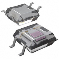


 工商网监
湘ICP备2023018690号
工商网监
湘ICP备2023018690号
