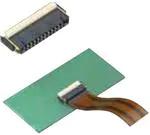
AYF53
For FPC/FFC*
FPC connectors
(0.5mm pitch)
Back lock
Y5B/Y5BW
Series
FEATURES
1. Low profile, space saving back lock
type with improved lever operability
2. Mechanical design freedom
achieved by top and bottom double
contacts
3. Wide selection, including a type
with a small number of pins
Low profile and space saving design of
1.0 mm high and 3.20 mm deep (3.70
mm with lever)
Y5B and Y5BW can have a minimum of
four and two contacts respectively,
maximum reduction in design
packaging.
Y5B
Y5BW
1.00
Structure to lock
notches on both ends
of the FPC with
holding contacts
Applicable FPC shape
With notches
(1) The inserted FPC can be temporarily held until the lever is
closed.
(2) When the lever is closed, the holding contacts lock the
FPC by its through-holes and notches, enhancing the FPC
holding force.
* (Y5BW is compatible with FPC only.)
Unit: mm
0
3.2
APPLICATIONS
4 pin contacts (Y5B: minimum)
• Wiring patterns can be located
underneath the connector.
• Man-hours for assembly can be
reduced by delivering the
connectors with their levers opened.
• Y5BW features advanced
functionality, including a structure to
temporarily hold the FPC and a
higher holding force.
The FPC holding contacts located on
both ends of the connector facilitate
positioning of FPC and further enhance
the FPC holding force.
A wide range of digital equipment,
including mobile phones,
smartphones, PCs, digital still camera,
and digital video camera. Ideal for
touch panels and LCD backlights,
which require connectors with a small
number of pins.
ORDERING INFORMATION
AYF 5
3
5
53: FPC Connector 0.5 mm pitch
(Back lock)
Number of pins (2 digits)
Function
3: Top and bottom double contacts (Y5B)
6: Top and bottom double contacts, lock holding type (Y5BW)
Surface treatment (Contact portion / Terminal portion)
5: Au plating/Au flash plating (Ni barrier)
ds_65315_en_y5b_y5bw: 311012J
1
�AYF53
PRODUCT TYPES
Y5B
Height
Y5BW
Number of pins
Part number
Number of pins
Part number
4
5
6
8
10
12
14
16
24
28
30
32
34
40
42
50
AYF530435
AYF530535
AYF530635
AYF530835
AYF531035
AYF531235
AYF531435
AYF531635
AYF532435
AYF532835
AYF533035
AYF533235
AYF533435
AYF534035
AYF534235
AYF535035
2
3
4
6
8
10
12
14
22
26
28
30
32
38
40
48
AYF530265
AYF530365
AYF530465
AYF530665
AYF530865
AYF531065
AYF531265
AYF531465
AYF532265
AYF532665
AYF532865
AYF533065
AYF533265
AYF533865
AYF534065
AYF534865
1.0 mm
Packing
Inner carton (1-reel)
Outer carton
5,000 pieces
10,000 pieces
Notes: 1. Order unit;
For volume production: 1-inner carton (1-reel) units
Samples for mounting check: 50-connector units. Please contact our sales office.
2. Please contact our sales office for connectors having a number of pins other than those listed above.
SPECIFICATIONS
1. Characteristics
Electrical
characteristics
Mechanical
characteristics
Item
Rated current
Rated voltage
Insulation resistance
Specifications
0.5A/pin contact (Except for holding contact)
50V AC/DC
Min. 1,000M (initial)
Breakdown voltage
250V AC for 1 min.
Contact resistance
Max. 100m
FPC holding force
Ambient temperature
Storage temperature
Y5B: Min. 0.2N/pin contacts pin contacts (initial)
Y5BW: Min. 0.2N/pin contacts pin contacts + 2.0N
(initial)
–55C to +85C
–55C to +85C (product only)
–40C to +50C (emboss packing)
Conditions
Using 250V DC megger (applied for 1 min.)
No short-circuiting or damage at a detection current of 1 mA
when the specified voltage is applied for one minute.
Based on the contact resistance measurement method
specified by JIS C 5402.
Measurement of the maximum force applied until the
inserted compatible FPC is pulled out in the insertion axis
direction while the connector lever is closed
No freezing at low temperatures. No dew condensation.
Conformed to MIL-STD-202F, method 107G
Thermal shock resistance
(with FPC inserted)
5 cycles,
insulation resistance min. 100M,
contact resistance max. 100m
Environmental
characteristics
Humidity resistance
(with FPC inserted)
Saltwater spray resistance
(with FPC inserted)
H2S resistance
(with FPC inserted)
Soldering heat resistance
Lifetime
characteristics
Unit weight
Insertion and removal life
Order Temperature (°C)
1
–55 −30
2
3
85 +30
4
–55 −30
Time (minutes)
30
Max. 5
30
Max. 5
120 hours,
insulation resistance min. 100M,
contact resistance max. 100m
24 hours,
insulation resistance min. 100M,
contact resistance max. 100m
48 hours,
contact resistance max. 100m
Peak temperature: 260C or less
300C within 5 sec. 350C within 3 sec.
Bath temperature 402C, gas concentration 31 ppm,
humidity 75 to 80% R.H.
Reflow soldering
Soldering iron
20 times
Repeated insertion and removal: min. 10 sec./time
Bath temperature 402C,
humidity 90 to 95% R.H.
Bath temperature 352C,
saltwater concentration 51%
Y5B (50 pin contacts): 0.16 g
2. Material and surface treatment
Part name
Molded portion
Material
Housing: LCP resin (UL94V-0)
Lever: LCP resin (UL94V-0)
Contact
Copper alloy
Holding contact portion
Soldering terminal portion
Copper alloy
Copper alloy
2
Surface treatment
—
Contact portion; Base: Ni plating, Surface: Au plating
Terminal portion; Base: Ni plating, Surface: Au plating
Terminal portion; Base: Ni plating, Surface: Au plating
Base: Ni plating, Surface: Au plating
ds_65315_en_y5b_y5bw: 311012J
�AYF53
DIMENSIONS (Unit: mm)
Interested in CAD data? You can obtain CAD data for all products with a
mark from your local Panasonic Electric Works representative.
CAD Data
Y5B
A
0.50±0.10
1.00±0.10
(3.70)
Number of pins/
dimension
4
A
B
C
4.00
3.36
1.50
5
6
8
10
12
14
16
24
28
30
32
34
40
42
50
4.50
5.00
6.00
7.00
8.00
9.00
10.00
14.00
16.00
17.00
18.00
19.00
22.00
23.00
27.00
3.86
4.36
5.36
6.36
7.36
8.36
9.36
13.36
15.36
16.36
17.36
18.36
21.36
22.36
26.36
2.00
2.50
3.50
4.50
5.50
6.50
7.50
11.50
13.50
14.50
15.50
16.50
19.50
20.50
24.50
(1.76)
1.60
(Suction
area)
Terminal coplanarity
0.30
0.1
0.50
(Contact and
soldering terminals)
B±0.20
2.90
3.20
(0.15)
(1.50)
(FPC
insertion
depth)
(0.32)
(0.15)
C±0.20
Y5B RECOMMENDED FPC/FFC DIMENSIONS
(Finished thickness: t = 0.30.03)
The conductive parts should be based by Ni plating and then Au plating.
Number of pins/
dimension
4
1.50
5
6
8
10
12
14
16
24
28
30
32
34
40
42
50
2.00
2.50
3.50
4.50
5.50
6.50
7.50
11.50
13.50
14.50
15.50
16.50
19.50
20.50
24.50
(A+1)±0.05
A±0.03
20
0.
R
0.30±0.03
2.50 min.
(Reinforcing plate)
(FPC) 0.35±0.03
(FFC) 0.30±0.03
1.50 min.
(Exposed part
of the conductor)
0.50±0.07
0.50±0.03
Cutting direction
Cut FPC from the copper foil side
to the reinforcing plate side.
A
Y5BW
A
3.70
1.60
(Suction
area)
(1.76)
1.00±0.10
0.50±0.10
Terminal coplanarity
B±0.20
0.1
(0.30)
(Contact, holding
(0.50)
contact and
soldering terminals)
(0.15)
ds_65315_en_y5b_y5bw: 311012J
D±0.20
C±0.20
(0.32)
(0.15)
(0.32)
(0.15)
2.90
3.20
(1.50)
(FPC
insertion
depth)
Number of pins/
dimension
2
A
B
C
D
4.00
3.36
1.50
0.50
3
4
6
8
10
12
14
22
26
28
30
32
38
40
48
4.50
5.00
6.00
7.00
8.00
9.00
10.00
14.00
16.00
17.00
18.00
19.00
22.00
23.00
27.00
3.86
4.36
5.36
6.36
7.36
8.36
9.36
13.36
15.36
16.36
17.36
18.36
21.36
22.36
26.36
2.00
2.50
3.50
4.50
5.50
6.50
7.50
11.50
13.50
14.50
15.50
16.50
19.50
20.50
24.50
1.00
1.50
2.50
3.50
4.50
5.50
6.50
10.50
12.50
13.50
14.50
15.50
18.50
19.50
23.50
3
�AYF53
Y5BW RECOMMENDED FPC DIMENSIONS
(Finished thickness: t = 0.30.03)
The conductive parts should be based by Ni plating and then Au plating.
Notches type
R0.20R
0.20
R0
.25
ma
x.
3
4
6
8
10
12
14
22
26
28
30
32
38
40
48
1.00
1.50
2.50
3.50
4.50
5.50
6.50
10.50
12.50
13.50
14.50
15.50
18.50
19.50
23.50
*1
Not interfere
conductor
2.50 min.
(Reinforcing plate)
x.
ma
.25
R0
0.50
*1
0.70±0.05 0.30±0.03
.20
R0
0.80±0.05
1.30±0.10
1.50 min.
(Conductor
exposed area)
(A+2)±0.05
A±0.03
0.50±0.03 (Pitch) 0.35±0.03
1.00±0.07
Number of pins/
dimension
2
Cutting direction (*2)
(*2) Cut FPC from the copper foil side
to the reinforcing plate side.
A
EMBOSSED TAPE DIMENSIONS (Unit: mm) (Common for respective contact type)
• Specifications for taping
Tape I
Tape II
(A±0.3)
(A±0.3)
(C)
(D±1)
(B)
Taping reel
Top cover tape
(1.75)
Embossed carrier tape
380 dia.
(2.0)
(4.0)
(1.75)
(2.0)
(4.0)
Leading direction after packaging
(B)
• Specifications for the plastic reel
(In accordance with EIAJ ET-7200B.)
Embossed mounting-hole
8.0
(8.0)
Label
1.5
.1
+0 0.0
50
1.
0 +00.1
.0
dia
a.
di
.
• Y5B Dimension table (Unit: mm)
Number of pins
4 to 10
12 to 30
32 to 34
40 to 50
Type of taping
Tape I
Tape I
Tape II
Tape II
A
16.0
24.0
32.0
44.0
B
7.5
11.5
14.2
20.2
C
–
–
28.4
40.4
D
17.4
25.4
33.4
45.4
Quantity per reel
5,000
5,000
5,000
5,000
A
16.0
24.0
32.0
44.0
B
7.5
11.5
14.2
20.2
C
–
–
28.4
40.4
D
17.4
25.4
33.4
45.4
Quantity per reel
5,000
5,000
5,000
5,000
• Y5BW Dimension table (Unit: mm)
Number of pins
2 to 8
10 to 28
30 to 32
38 to 48
Type of taping
Tape I
Tape I
Tape II
Tape II
• Connector orientation with respect to embossed tape feeding direction
Type
Direction
of tape progress
4
Y5B
Y5BW
ds_65315_en_y5b_y5bw: 311012J
�AYF53
NOTES
1. Recommended PC board and metal
mask patterns
Connectors are mounted with high pitch
density, intervals of 0.3 mm or 0.5 mm.
In order to reduce solder bridges and
other issues make sure the proper levels
of solder is used.
The figures to the right are recommended
metal mask patterns. Please use them as
a reference.
• Y5B/Y5BW
0.50±0.03
0.30±0.03
0±0.03
0±0.03
0.80±0.03
0.80±0.03
Recommended PC board pattern
(mounting layout)
(TOP VIEW)
1.00±0.03
Recommended metal mask pattern
0.50±0.01
0±0.01
0±0.01
1.00±0.01
0.80±0.01
0.31±0.01
Metal mask thickness: Here, 120m
(Terminal portion opening area ratio: 31.8%)
(Soldering terminal portion opening area ratio: 100%)
0.25±0.01
2. Precautions for insertion/removal of
FPC
Do not apply an excessive load to the
lever in the opening direction beyond its
open position; otherwise, the lever may
be deformed or removed.
Do not open/close the lever without an
FPC inserted; otherwise, the terminals
may be deformed, and the FPC insertion
force may increase.
Do not apply an excessive load to the
lever in a direction perpendicular to the
lever rotation axis or in the lever opening
direction; otherwise, the terminals may
be deformed, and the lever may be
removed.
These connectors are of the back lock
type, which has the FPC insertion section
on the opposite side of the lever.
Carefully place the FPC in the insertion
position or the lever opening/closing
position. Otherwise, a contact failure or
connector breakage may occur.
These connectors have top and bottom
double contacts. Do not insert an FPC
upside down. Inserting an FPC in a
direction opposite to that you intended
may cause an operation failure or
malfunction.
Fully open the lever to insert an FPC.
Completely insert the FPC horizontally.
An FPC inserted at an excessive angle to
the board may cause the deformation of
metal parts, FPC insertion failures, and
FPC circuit breakages.
Insert the FPC to the full depth of the
connector without altering the angle.
To close the lever, turn down the lever by
pressing the entire lever or both sides of
the lever with fingers tips.
If pressure to the lever is applied
unevenly, such as to an edge only, it may
deform or break. Also, make sure that the
lever is closed completely. Not doing so
will cause a faulty connection.
Avoid applying an excessive load to the
top of the lever during or after closing the
lever. Otherwise, the terminals may be
deformed.
When opening the lever to remove the
FPC, ensure that the lever will not go
over the initial position; otherwise, the
lever may be removed.
Remove the FPC at parallel with the lever
fully opened. If the lever is closed, or if
the FPC is forcedly pulled, the product or
FPC may break.
If a lever is accidentally detached during
the handling of a connector, do not use
the connector any longer.
After an FPC is inserted, carefully handle
it so as not to apply excessive stress to
the base of the FPC.
3. Cautions for using Y5BW
The holding contacts cannot be used as
conductors.
The holding contacts are located on both
ends of the contacts, and the shape of
the soldered portions is the same as that
of the other contacts. Use caution to
ensure connect identification.
Please refer to the latest product
specifications when designing your
product.
For Cautions for Use, see the “GENERAL NOTES FOR USING FPC
CONNECTORS” in the Connector Technical Information. For other details,
please verify with the product specification sheets.
ds_65315_en_y5b_y5bw: 311012J
5
�


 工商网监
湘ICP备2023018690号
工商网监
湘ICP备2023018690号
