Digital Pressure Sensor with Auto-reference Function
Digital
Auto reference
DP5/DPH
Head-separated
PRESSURE SENSORS
DP3 SERIES
DP2
DP3
Digital Display
DP4
High accuracy sensing
at all times with autoreference function
* Passed the UL 991 Environment Test
* UL 61010C-1 compatible, Passed the UL 991 Environment Test based on SEMI S2-0200.
[Category applicable for semiconductor manufacturing: TWW2, Process Equipment]
[Applicable standards: UL 61010C-1]
[Additional test / evaluation standards as per intended use: UL991, SEMI S2-0200]
Conforming to
EMC Directive
UL Recognition
Example of air-leak test
Threshold level
Auto-reference function follows
reference pressure changes
OK
NG
Reference pressure
e
sur
• Unaffected by changes in reference pressure
By an external signal, the set (threshold) values are
corrected by being shifted by an amount equal to the
pressure change. Hence, judgment by the sensor is
as accurate as before the reference pressure change.
This function is extremely suitable in places having
intense variations in the reference pressure or where
fine settings are required.
res
ep
enc
fer
Re hange
c
Reference
pressure
Before reference pressure change
NG?
NG
OK
NG
Reference
pressure
Reference
pressure
Pressure sensor not incorporating
auto-reference function
DP3 series
After reference pressure change
• Total cost reduction
Till now...one sensor was required for each suction
nozzle
Since the threshold level differs with the suction nozzle, a
sensor was required for each suction nozzle, increasing
the cost significantly.
( Atmospheric
pressure )
In case of DP3...operation efficiency UP!
Since the threshold level can be automatically changed
by the auto-reference function, two suction nozzles can
be used, alternately, with one sensor.
DP3-80
Suction nozzle for trimmers
Auto-reference input
PE
LED Bar Display
DP-M
Incorporates auto-reference function
Suction nozzle for
chip components
For chip components
Vacuum
Before suction Suction OK Suction NG Suction over
Threshold
level for
suction nozzle
for trimmers
Threshold
level for
suction nozzle
for chip
components
MODE
Electromagnetic valve
For trimmers
808
Ramco Innovations - 1207 Maple Street, West Des Moines IA USA 50265 - 800-280-6933 - www.ramcoinnovations.com
�2.5 ms or less
Comparative ON
Output 1
OFF
Hysteresis
Repeatability
Hysteresis Hysteresis
Set Value 1 Set Value 2 Set Value 3 Set Value 4
(P-1) (P-2)
(P-3)
(P-4)
High pressure
(Positive pressure type)
High vacuum
(Vacuum pressure type)
Set Value 1 Set Value 2 Set Value 3 Set Value 4
(P-1)
(P-2)
(P-3)
(P-4)
High pressure
(Positive pressure type)
High vacuum
(Vacuum pressure type)
Hysteresis: 1 digit (2 digits when using psi unit)
Note: The auto-reference function acts only on
Set Value 3 (P-3) and Set Value 4 (P-4) of
Comparative Output 2.
Note: The auto-reference function acts only on
Set Value 3 (P-3) and Set Value 4 (P-4) of
Comparative Output 2.
Optimum for leak test
Leak test mode
This mode is optimally suitable for a
leak test since Comparative Output 1
can be set to the hysteresis mode and
Comparative Output 2 can be set to the
window comparator mode.
Forced output mode Suitable for start-up check
The comparative outputs are forcibly
maintained in the OFF state in the
sensing mode, irrespective of the set
values.
Also, since the comparative outputs
can be forcibly made ON or OFF with
key operation, without actually applying
pressure, this mode is suitable for an
operation check or a start-up check.
3
Hysteresis
(Variable)
Comparative ON
Output 1 OFF
Hysteresis Hysteresis
(Fixed)
(Fixed)
MODE
key
Press
MODE
Selection can be made according to
mounting method or place of use.
Standard type / DP3-2�
DP
2-20
–101
.3k
Pa
OU
T1
0-A
DJ
OU
T2
MO
DE
Direct piping
Mounting on a
panel
Light weight type / DP3-80
Total weight
70 g approx.
ON
OFF
ON
Comparative
Output 2
Sensing mode
OFF
Forced output mode
Sensing mode
MO
DE
Hysteresis (fixed): 1 digit (2 digits when using psi unit)
Note: The auto-reference function acts only on
Set Value 3 (P-3) and Set Value 4 (P-4) of
Comparative Output 2.
The sensor
can be
mounted on
the suction
head of a chip
mounter.
Direct mounting on a wall
Selection from six pressure units
Analog bar display
Peak hold / bottom hold display
The pressure unit can be selected from
six different systems to suit your
requirement.
The selectable pressure units differ
with the sensor type. When the pressure unit is changed, the measured
pressure value and the set values
are automatically converted.
Pressure changes can also be displayed
in an analog fashion using LED bars.
Hence, sudden pressure changes can be
recognized at a glance.
LED bars indicate the pressure level
in steps of 10 % F.S., regardless of
the pressure unit.
The peak value or the bottom value of
the varying pressure can be displayed.
This function is convenient for finding
the pressure variation range or for
determining a reference for pressure
settings.
(
)(
)
Analog bar display
Digital display
International
System of
Units (SI)
kPa (Note)
kgf/cm2
mmHg
psi
bar
Pressure
DP3-41
inHg
Peak
value
OUT1
100kPa
OUT2
MODE
0-ADJ
Peak value is displayed if
key is pressed continuously.
DP3-41
: Vacuum pressure type
: Positive pressure type
Note: ‘MPa’ in case of DP3-22 and DP3-42.
PRESSURE SENSORS
A wide variety of models
Flat type / DP3-4�
key
Comparative
Output 1
Set Value 1 Set Value 2 Set Value 3 Set Value 4
(P-1)
(P-2)
(P-3)
(P-4)
High pressure
(Positive pressure type)
High vacuum
(Vacuum pressure type)
Within�1 % F.S.
Note: The response time is 7.5 ms, or less, at the
time of auto-reference input.
4
Press
Temperature characteristics
Within�0.2 % F.S.�1 digit
ON
Comparative
Output 2 OFF
(Note)
0
DP4
Comparative ON
Output 1
OFF
ON
Comparative
Output 2 OFF
(Note)
0
Response time
Hysteresis Hysteresis
Hysteresis
ON
Comparative
Output 2 OFF
(Note)
0
It achieves a 2.5 ms, or less, response
time at a high resolution of 1/1,000.
It enables highly accurate sensing with its
excellent repeatability and temperature
characteristics.
DP-M
2 Window comparator mode
The comparative outputs can be made
ON or OFF by a pressure within the set
range.
Since Comparative Output 1 can be used
as a self-diagnosis output, it is possible
to specify the auto-reference input range.
LED Bar Display
PE
1 Hysteresis mode
The hysteresis of the comparative
outputs can be set, as desired, with the
set values.
High accuracy • high resolution • high speed
Digital Display
DP3
DP2
Two outputs with four independent settings and four output modes
enable control as per your requirement
Head-separated
DP5/DPH
DP3
Bottom
value
OUT1
100kPa
OUT2
MODE
0-ADJ
Bottom value is
displayed if
key is pressed
continuously.
Time
Note: The above graph is for a positive pressure
type sensor.
Ramco Innovations - 1207 Maple Street, West Des Moines IA USA 50265 - 800-280-6933 - www.ramcoinnovations.com
809
�PRESSURE SENSORS
DP5/DPH
Head-separated
DP3
APPLICATIONS
Confirmation of chip component suction
The auto-reference function can compensate for the difference in suction
levels due to suction nozzle separation
distance. The vacuum type can be
mounted close to the chip mounter
suction head since it weighs only 70 g.
Air-leak test for PET bottles
Leak test mode, which is an output
mode optimally suitable for an air-leak
test, has been incorporated. It can reliably detect even a small air-leak.
Because of the auto-reference function, it is safe even if the filling pressure
varies.
DP3-41
DP3-80
10
0k
DP4
OU
MO
MO
Pa
3-41
DP
OU
DE
T2
DE
T1
DJ
0-A
IC
Model No.
�101 kPa type
Appearance
0 to�101.3 kPa
DP3-20
0 to 100.0 kPa
DP3-21
0 to 1.000 MPa
DP3-22
Pressure port
Comparative outputs
Rc (PT) 1/8
female thread
�101 kPa type
0 to�101.3 kPa
DP3-80
100 kPa type
NPN
open-collector
transistor
0 to 100.0 kPa
DP3-41
1 MPa type
Positive pressure
Vacuum pressure
Positive pressure
Flat
Light weight
PE
LED Bar Display
Standard
DP-M
Vacuum
pressure
Type
810
Rated pressure range
100 kPa type
ORDER GUIDE
1 MPa type
DP2
DP3
Digital Display
IC tray
0 to 1.000 MPa
M5 female thread
Rc (PT) 1/8
female thread
DP3-42
Ramco Innovations - 1207 Maple Street, West Des Moines IA USA 50265 - 800-280-6933 - www.ramcoinnovations.com
�OPTIONS
Sensor mounting bracket
MS-DPX
Sensor mounting
bracket
(For standard type)
Mounting bracket for standard type
Two M4 (length 6 mm 0.236 in) pan head screws and two spring
washers are attached.
[
• MS-DPX-4
]
DP
3-2
0
–101
.3k
Pa
OU
T1
Back angled mounting bracket for standard type
Two M4 (length 6 mm 0.236 in) pan head screws and two spring
washers are attached.
DPX-03
Changes the pressure port from female thread [Rc (PT) 1/8] to
male thread [R (PT) 1/8].
Panel mounting
bracket
(For standard type)
MS-DPX-2
It can be used for mounting on a panel
(1 to 3.2 mm 0.039 to 0.126 in thick).
Front protection
cover
(For standard type)
DPX-04
It protects the sensor’s adjustment panel.
(It can be fitted when the panel mounting bracket is used.)
[
0-AD
J
]
Two M4 (length 6 mm 0.236 in)
pan head screws and two
spring washers are attached.
OU
T2
MOD
E
Two M4 (length 6 mm 0.236 in)
pan head screws and two
spring washers are attached.
DP4
MS-DPX-4
Straight bush
• MS-DPX
Description
Straight bush
• DPX-01 [Pressure port attachment (Standard type only)]
• DPX-02 [Hexagon-socket-head plug for pressure port (Standard type only)]
Pressurer port attachment DPX-01
Straight
bush
Digital Display
DP3
DP2
Accessories
• DPX-03
Panel mounting bracket,
Front protection cover
• MS-DPX-2
• DPX-04
Front protection
cover DPX-04
DP
2-20
–10
OU
1.3
kPa
T1
OU
0-A
DJ
T2
MO
DE
Panel mounting bracket
MS-DPX-2
Suitable for 1 to 3.2 mm
0.039 to 0.126 in thick panel
(
)
Ramco Innovations - 1207 Maple Street, West Des Moines IA USA 50265 - 800-280-6933 - www.ramcoinnovations.com
LED Bar Display
PE
Hexagon-socket-head plug
for pressure port DPX-02
DP-M
Model No.
Head-separated
DP5/DPH
Designation
PRESSURE SENSORS
DP3
811
�PRESSURE SENSORS
DP5/DPH
Head-separated
DP4
DP3
SPECIFICATIONS
Type
Item
Model No.
Vacuum pressure
�101 kPa type
Standard
Light weight
DP3-20
DP3-80
DP3-21
Type of pressure
0 to�101.3 kPa
Rated pressure range
DP3-22
DP3-42
0 to 100.0 kPa
0 to 1.000 MPa
Set pressure range
(Note 1)
5.1 to�101.3 kPa
0.052 to�1.033 kgf/cm2, 0.051 to�1.013 bar
0.74 to�14.70 psi, 38 to�760 mmHg
1.5 to�29.9 inHg
�5.0 to 100.0 kPa
�0.051 to 1.020 kgf/cm2, �0.050 to 1.000 bar
�0.72 to 14.50 psi
�0.050 to 1.000 MPa
�0.51 to 10.20 kgf/cm2, �0.50 to 10.00 bar
�7.2 to 145.0 psi
Settable range
(Note 2)
101.3 to�101.3 kPa
1.033 to�1.033 kgf/cm2, 1.013 to�1.013 bar
14.70 to�14.70 psi, 760 to�760 mmHg
29.9 to�29.9 inHg
�100.0 to 100.0 kPa
�1.020 to 1.020 kgf/cm2, �1.000 to 1.000 bar
�14.50 to 14.50 psi
�1.000 to 1.000 MPa
�10.20 to 10.20 kgf/cm2,�10.00 to 10.00 bar
�145.0 to 145.0 psi
490 kPa
Applicable fluid
kPa, kgf/cm2, bar, psi, mmHg, inHg
Current consumption
(
50 mA or less
)
DC-12 or DC-13
Equipped with 4 types of modes: hysteresis mode, window comparator mode, leak test mode, forced output mode
(selectable by key operation)
Output modes
Hysteresis
1 digit (however, variable in hysteresis mode, variable for Comparative Output 1 only when using leak test mode, and 2 digits when using psi unit)
Within�0.2 % F.S.�1 digit
Repeatability
Response time
2.5 ms or less [7.5 ms or less with auto-reference input (Note 3)]
Short-circuit protection
Incorporated
NPN non-contact input [operates in Low (fall) state]
• Input signal condition: High...5 to 30 V or open
Low...0.4 V or less (0.5 mA, or less, source current)
Low level input time...1 ms or more
Reference pressure duration...1 ms or more
Auto-reference input
Display
31/2 digit red LED display (Sampling rate: 4 times/sec. approx.)
Displayable pressure range
Analog bar display
5.1 to�101.3 kPa
0.052 to�1.033 kgf/cm2, 0.051 to�1.013 bar
0.74 to�14.70 psi, 38 to�760 mmHg
1.5 to�29.9 inHg
�5.0 to 100.0 kPa
�0.051 to 1.020 kgf/cm2,�0.050 to 1.000 bar
�0.72 to 14.50 psi
�0.050 to 1.000 MPa
�0.51 to 10.20 kgf/cm2,�0.50 to 10.00 bar
�7.2 to 145.0 psi
LED bar display in steps of 10 % F.S. approx.
Operation Comparative Output 1
indicators Comparative Output 2
Pollution degree
Environmental resistance
MPa, kgf/cm2, bar, psi
NPN open-collector transistor
• Maximum sink current: 100 mA
• Applied voltage: 30 V DC or less (between comparative output and 0 V)
• Residual voltage: 1 V or less (at 100 mA sink current)
0.4 V or less (at 16 mA sink current)
Utilization category
DP-M
kPa, kgf/cm2, bar, psi
10
12 to 24 V DC �
�15 % Ripple P-P 10 % or less
Supply voltage
Comparative outputs
Comparative Output 1
Comparative Output 2
1.47 MPa
Non-corrosive gas
Selectable units
DP2
DP3
Digital Display
DP3-41
Gauge pressure
Pressure withstandability
PE
LED Bar Display
Positive pressure
100 kPa type
1 MPa type
Standard
Flat
Standard
Flat
Orange LED (lights up when Comparative Output 1 is ON)
Green LED (lights up when Comparative Output 2 is ON)
3 (Industrial environment)
Protection
IP40 (IEC)
Ambient temperature
�10 to�50 �C �14 to�122 �F (No dew condensation or icing allowed), Storage: �10 to�60 �C �14 to�140 �F
Ambient humidity
35 to 85 % RH, Storage: 35 to 85 % RH
EMC
EN 50081-2, EN 50082-2, EN 61000-6-2
Voltage withstandability
1,000 V AC for one min. between all supply terminals connected together and enclosure
Insulation resistance
50 MΩ, or more, with 500 V DC megger between all supply terminals connected together and enclosure
Vibration resistance
10 to 150 Hz frequency, 0.75 mm 0.030 in amplitude in X, Y and Z directions for two hours each
100 m/s2 acceleration (10 G approx.) in X, Y and Z directions for three times each
Shock resistance
Temperature characteristics
Pressure port
Material
Cable
Cable extension
Weight
Accessories
Over ambient temperature range �10 to�50 �C �14 to�122 �F: within�1 % F.S. of detected pressure at �20 �C �68 �F
Standard type: Rc (PT) 1/8 female thread, Flat type: Rc (PT) 1/8 female thread, Light weight type: M5 female thread
Front case: ABS, Rear case: PPS (glass fiber reinforced), Display surface: Acrylic
Pressure port attachment: Die-cast zinc alloy [Light weight type: POM (glass fiber reinforced), pressure port is brass (nickel plated)]
0.15 mm2 5-core oil resistant cabtyre cable, 2 m 6.562 ft long
Extension up to total 100 m 328.084 ft (less than 10 m 32.808 ft when conforming to CE marking) is possible with 0.3 m2, or more, cable.
Standard type: 95 g approx., Flat type: 120 g approx., Light weight type: 70 g approx.
DPX-02 (Hexagon-socket-head plug for pressure port): 1 pc. (Standard type only), Pressure unit label: 1 pc.
Notes: 1) The set pressure range is the settable pressure range for Set Value 1 (P-1) and Set Value 2 (P-2).
2) The settable range is the settable pressure range for Set Value 3 (P-3) and Set Value 4 (P-4). It caters to the auto-reference function and is much wider
than the rated pressure range.
3) Refer to ‘Time chart’ under ‘Auto-reference function’ on p.816.
812
Ramco Innovations - 1207 Maple Street, West Des Moines IA USA 50265 - 800-280-6933 - www.ramcoinnovations.com
�I/O CIRCUIT AND WIRING DIAGRAMS
Wiring diagram
Color code
(Brown)�V
Auto-reference
(Pink) input (Note)
(Black) Comparative Output 1
Tr1
ZD1
Tr2
ZD2
Internal circuit
Load
Load
100 mA max.
(White) Comparative Output 2
(Blue) 0 V
� 12 to 24 V DC
10
� �
�15 %
100 mA max.
DP3-80
–101.3kPa
OUT1
OUT2
MODE
0-ADJ
Users’ circuit
Note: If you do not use the auto-reference input (pink),
always connect it to �V (brown).
DP4
Sensor circuit
D
Head-separated
DP5/DPH
I/O circuit diagram
PRESSURE SENSORS
DP3
Brown
Load
Pink
Symbols ... D: Reverse supply polarity protection diode
ZD1, ZD2 : Surge absorption zener diode
Tr 1 , Tr 2 : NPN output transistor
Black
Load
� 12 to 24 V DC
10
� �
�15 %
Digital Display
DP3
DP2
White
Blue
PRECAUTIONS FOR PROPER USE
Operation
• If setting is impossible even with pressing the MODE key,
verify whether the key-protect function is enabled. Please
note that pressing down on the MODE key for an
extended moment will enable the key-protect function as
soon as the key is released.
• If using the window comparator mode, set the pressure
values so that there is a difference of 3 digits, or more,
between Set Value 1 (P-1) and Set Value 2 (P-2), and
between Set Value 3 (P-3) and Set Value 4 (P-4). No
output will be possible with a 0 to 2 digit difference.
Wiring
• Make sure that the power supply is off while wiring.
• Verify that the supply voltage variation is within the rating.
• If power is supplied from a commercial switching regulator,
ensure that the frame ground (F.G.) terminal of the power
supply is connected to an actual ground.
• In case noise generating equipment (switching regulator,
inverter motor, etc.) is used in the vicinity of this sensor,
connect the frame ground (F.G.) terminal of the equipment
to an actual ground.
• Do not run the wires together with high-voltage lines or
power lines or put them in the same raceway. This can
cause malfunction due to induction.
Conditions in use for CE conformity
• The DP3 series is a CE conformity product complying with
EMC Directive. The harmonized standard with regard to
immunity that applies to this product is EN 61000-6-2
(Note) and the following condition must be met to conform
to that standard.
Condition
• The sensor should be connected less than 10 m 32.808 ft
from the power supply.
Note: The EN 50082-2 that previously applied to the products for conforming
to EMC Directive was replaced by EN 61000-6-2 staring April 1st, 2002.
Others
• Use within the rated pressure range.
• Do not apply pressure exceeding the pressure withstandability value. The diaphragm will get damaged and
correct operation shall not be maintained.
• Do not use during the initial transient time (0.5 sec.) after
the power supply is switched on.
• Avoid dust, dirt, and steam.
• Take care that the sensor does not come in direct contact
with water, oil, grease, or organic solvents, such as,
thinner, etc.
• Do not insert wires, etc., into the pressure port. The
diaphragm will get damaged and correct operation shall
not be maintained.
• Do not operate the keys with pointed or sharp objects.
Ramco Innovations - 1207 Maple Street, West Des Moines IA USA 50265 - 800-280-6933 - www.ramcoinnovations.com
813
LED Bar Display
PE
• This product is not a safety sensor. Its use is not
intended or designed to protect life and prevent
body injury or property damage from dangerous
parts of machinery. It is a normal pressure
detection sensor.
• The DP3 series is designed for use with noncorrosive gas. It cannot be used with liquid or corrosive gas.
DP-M
All models
�PRECAUTIONS FOR PROPER USE
All models
Functional description
–101.3kPa
3
2
Cause
Overcurrent due to short- Switch off the power supply
circuit.
and check the load.
OUT2
MODE
Applied pressure at the
Pressure is being applied pressure port should be
during zero-point adjust- brought to atmospheric presment.
sure and zero-point adjustment should be done again.
0-ADJ
DP4
4
6
5
Displays measured pressure, settings, error
messages and key-protect status.
Comparative Output
2 1 operation indicator
(Orange)
Lights up when Comparative Output 1 is ON.
Comparative Output
3 2 operation indicator
(Green)
Lights up when Comparative Output 2 is ON.
4
• In the initial setting mode, pressing the
key changes the settable digit.
• In the Set Value 1 to 4 modes, pressing the key changes the set value to
the high pressure side in case of
positive pressure type sensor and to
the high vacuum side in case of
vacuum pressure type sensor.
• In the sensing mode, if the key is
pressed continuously for 4 sec. or more,
the display shows peak hold value.
Increment key (
5 Decrement key (
6
)
• In the initial setting mode, pressing the
key changes the set conditions.
• In the Set Value 1 to 4 modes, pressing the key changes the set value to
the low pressure side in case of
)
positive pressure type sensor and to
the low vacuum side in case of
vacuum pressure type sensor.
• In the sensing mode, if the key is
pressed continuously for 4 sec. or more,
the display shows bottom hold value.
Mode selection key
( MODE )
In the sensing mode, if both the keys are pressed
simultaneously, zero-point adjustment is done.
PE
LED Bar Display
Function
31/2 digit LED
1
display (Red)
DP-M
DP2
DP3
Digital Display
Description
Applied pressure
exceeds the upper
limit of displayable
pressure range.
Applied pressure
exceeds the lower
limit of displayable
Applied pressure should be
pressure range.
brought within the rated
Applied pressure pressure range.
exceeds the lower
limit of displayable
pressure range.
Applied pressure
exceeds the upper
limit of displayable
pressure range.
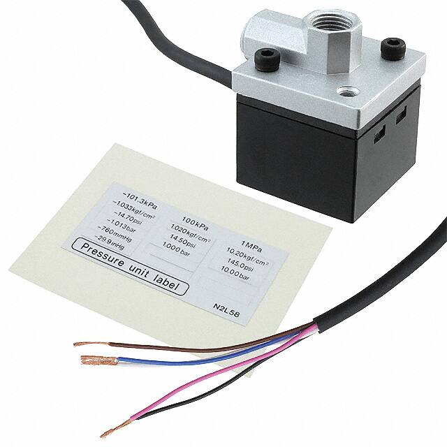
Label for change in pressure unit
• When a pressure unit other than ‘kPa’ ( ) or ‘MPa’ ( ) has
been selected in the initial setting mode, the label (supplied
as accessory) which corresponds to the selected unit
should be stuck at the position shown in the figure below.
Pressure unit label (accessory)
• Each press of the key changes the selected
mode to sensing mode, Set Value 1 (P-1) to
Set Value 4 (P-4) set mode.
• In the sensing mode, if the key is pressed
continuously for about 3 sec., key-protect can
be set / released.
• In the sensing mode, if the mode selection
key is pressed while pressing the increment
key(
), the initial setting mode is obtained.
DP3-80
–101.3kPa
OUT1
OUT2
Stick the pressure unit label
at the position shown.
MODE
0-ADJ
Conversion of pressure units
• In the DP3 series, the conversion
to different units is automatically
done on changing the setting of
the pressure unit. However, this
conversion can also be obtained
by multiplying the values by the
coefficients given in the table on
the right.
Conversion procedure
• For example, if 2 kPa is to be expressed
in kgf/cm2,
since 1 kPa�1.01972 10�2 kgf/cm2,
2 kPa becomes
2 1.01972 10�2c0.020 kgf/cm2.
814
Corrective action
Positive
pressure
type
OUT1
Error message
Vacuum
pressure
type
DP3-80
Positive
pressure
type
1
Error messages
• When an error occurs, take the following corrective action.
Vacuum
pressure
type
DP5/DPH
Head-separated
PRESSURE SENSORS
DP3
Conversion table for pressure units
kPa
kgf/cm2
MPa
1
1 kPa
1
1 MPa
1 103
10�3
1.01972
1
1.01972 10
1 kgf/cm2 9.80665 10 9.80665
10�2
1bar
1 102
1psi
6.89473
1 10�1
10�2
1
1.01972
bar
psi
1
10�2
1 10
9.80665
10�1
1
6.89473 10�3 7.03065 10�2 6.89473 10�2
1.45038
10�1
3.3864 10�3 3.4531 10�2 3.3864 10�2
3.3864
1 atm
1.01325
102
1.01325
10�1
1.03323
1.01325
inHg
atm
7.50062
0.2953
9.86923 10�3
1.45038 102 7.50062 103 0.2953 103
9.86923
1.42234 10 7.35559 102 2.8959 10 9.67841 10�1
1.45038 10 7.50062 102
1
1 mmHg
1.33322 10�1 1.33322 10�4 1.35951 10�3 1.33322 10�3 1.93368 10�2
(1Torr)
1 inHg
mmHg
(Torr)
0.4912
5.17147 10
2.953 10
9.86923 10�1
2.036
6.80457 10�2
3.9370
1
2.5400 10
1.46960 10 7.60000
102
10�2
1.31579 10�3
1
3.342 10�2
2.9921 10
1
Ramco Innovations - 1207 Maple Street, West Des Moines IA USA 50265 - 800-280-6933 - www.ramcoinnovations.com
�Setting
• If key-protect has been set, make sure to release key-protect before operating the keys.
(Please refer to ‘Key-protect function’ on p.817 for the procedure.)
• Set Value 1 to 4 (P-1 to P-4) can be made common for all the output modes.
• In the positive pressure type sensor, Set Value 2 (P-2) and Set Value 4 (P-4) can be set only towards the high pressure side
with respect to Set Value 1 (P-1) and Set Value 3 (P-3), respectively.
In the vacuum pressure type sensor, Set Value 2 (P-2) and Set Value 4 (P-4) can be set only towards the high vacuum
side with respect to Set Value 1 (P-1) and Set Value 3 (P-3), respectively.
• Auto-reference function acts on Set Value 3 (P-3) and Set Value 4 (P-4) only.
• Set Value 5 (P-5) is the auto-reference input value. If auto-reference input is not applied, Set Value 5 (P-5) is zero.
• The conditions which are set are stored in an EEPROM. Kindly note that the EEPROM has a life span and its guaranteed
life is 100,000 write operation cycles. However, since the auto-reference input value [Set Value 5 (P-5)] is not written into
the EEPROM, it is not included in the number of write operation cycles.
PRESSURE SENSORS
All models
DP4
PRECAUTIONS FOR PROPER USE
Head-separated
DP5/DPH
DP3
1 Zero-point adjustment
2 Initial setting
3 Pressure value setting
Measurement
Adjust zero-point
Set ‘Display’, ‘Output mode’,
and ‘Unit’
Enter Set Value 1 to 4
(P-1 to P-4)
Commence measurement
on completion of setting
1 Zero-point adjustment
3 Pressure value setting
• The displayed pressure when the pressure port is left
open is adjusted to zero.
• Set Value 1 to 4 (P-1 to P-4) of the comparative outputs are set.
• The sensor will automatically enter the sensing
mode when power is supplied.
• Let the pressure port be at atmospheric pressure
(i.e., no applied pressure condition), and press,
simultaneously, the increment and decrement
keys continuously.
•
is displayed and, when the fingers are
released, zero-point adjustment is completed and
the sensor returns to the sensing mode.
2 Initial setting
DP3-80
–101.3kPa
OUT1
OUT2
DP3-80
–101.3kPa
OUT1
OUT2
MODE
0-ADJ
• At each press of MODE key, the mode changes, in
rotation, to Set Value 1 (P-1) set mode, Set Value 2
(P-2) set mode, Set Value 3 (P-3) set mode, Set
Value 4 (P-4) set mode, Set Value 5 (P-5) display
mode and sensing mode.
Digital Display
DP3
DP2
Setting procedure
MODE
OUT1
–101.3kPa
• In the sensing mode, press
ing
key.
MODE
MODE
0-ADJ
Press
is
• The settable digit blinks.
• The settable digit changes when
key is pressed.
• The setting is changed when
key is pressed.
Change with
3rd digit
displayed.
2
Vacuum
Positive
pressure type pressure type
MODE
key
Press
Set Value 1 (P-1) set mode
Output mode
MODE
key
Set Value 5 (P-5) display mode
6
• Enter Set Value 1 (P-1)
using
key and
key.
• Auto-reference input value
is displayed.
In case auto-reference input has not
been applied, zero is displayed.
1st digit
Press
Unit
• At the time of auto-reference
input,
is displayed, and
the sensed pressure value is
recorded in Set Value 5 (P-5).
key
2nd digit
Sensing mode
key while press-
• Initial setting is displayed.
• If sensor is being used for the first time,
displayed.
OUT2
1’
Display
: kPa or
MPa
: Hysteresis
mode
: Digital
display
: kgf/cm2
: Window
comparator
mode
: Analog
bar
display
: bar
: Leak test
mode
: psi
: Forced output
mode
: mmHg
: inHg
• If the output mode has been set to the window comparator
mode ( ), set the pressure values so that there is a difference
of 3 digits, or more, between Set Value 1 (P-1) and Set Value 2
(P-2), and between Set Value 3 (P-3) and Set Value 4 (P-4).
Also, if the output mode has been set to the leak test mode ( ), set
the pressure values so that there is a difference of 3 digits, or more,
between Set Value 3 (P-3) and Set Value 4 (P-4). However, when
unit is set to ‘psi’ ( ), the difference should be 6 digits, or more.
3
MODE
key
Press
Set Value 2 (P-2) set mode
5
• Enter Set Value 2 (P-2)
using
key and
key.
Press
4
MODE
key
Set Value 4 (P-4) set mode
• Enter Set Value 4 (P-4) using
key and
key.
MODE
key
Press
MODE
key
Set Value 3 (P-3) set mode
• Enter Set Value 3 (P-3)
using
key and
key.
• The pressure values can be set only when the output mode has
been set to hysteresis mode ( ), window comparator
mode ( ) or leak test mode ( ). If the output mode has been set
to the forced output mode ( ), pressure values cannot be set.
Ramco Innovations - 1207 Maple Street, West Des Moines IA USA 50265 - 800-280-6933 - www.ramcoinnovations.com
815
LED Bar Display
PE
• Sensed pressure value is
• Pressure ‘Unit’, ‘Display’ and ‘Output mode’ of the
comparative outputs are set.
DP3-80
Sensing mode
Auto-reference
input
1
DP-M
0-ADJ
�PRECAUTIONS FOR PROPER USE
All models
Auto-reference function
Principle
• Auto-reference function corrects Set Value 3 (P-3) and Set Value 4
(P-4) of Comparative Output 2 by taking the pressure measured at
the time of auto-reference input as the reference pressure.
Comparative
Output 2
OFF
Atmospheric pressure
P-3
Pressure
P-4
DP2
DP3
Digital Display
• When there is no auto-reference input, the atmospheric pressure
is taken as the reference pressure for Set Value 3 (P-3) and Set
Value 4 (P-4).
DP-M
P-2 Suction nozzle clogging error range
OK product
P-1
Auto-reference input
ON
P-3’�P-3�P-5
Comparative
Output 2
OFF
Atmospheric pressure P-5
P-3’
P-4’
Pressure
that instant is temporarily recorded as Set Value 5 (P-5) and
becomes the reference pressure.
• With Set Value 5 (P-5) as the reference pressure, Set Value 3
(P-3) and Set Value 4 (P-4) are automatically corrected to ‘Set
Value 3 (P-3)�Set Value 5 (P-5)’ and ‘Set Value 4 (P-4)�Set
Value 5 (P-5)’, respectively.
Settable range and set pressure range after correction
• The settable range of Set Value 3 (P-3) and Set Value 4 (P-4) is wider
than the rated pressure range to cater to the auto-reference function.
• At the time of auto-reference input, if the corrected set value
exceeds the set pressure range, the set value is automatically
corrected to be within the set pressure range. Hence, please
see that the set pressure range is not exceeded.
Settable range (P-3, P-4)
Set pressure range (P-3 and P-4 after correction)
Rated pressure range
P-4’�P-4�P-5
b P-3’�P-3�P-5
a
NG product
P-5
Auto-reference input
Suction level can be specified with respect to
the atmospheric pressure
P-4
P-3
b
0 a
P-4’�P-4�P-5
Pressure change
• At the time of auto-reference input, the pressure value detected at
PE
LED Bar Display
Application examples
(1) Confirmation of PCB mount component suction (Using hysteresis mode)
• Pressure judgment errors due to suction nozzle type, suction
nozzle clogging, reference pressure changes, etc., are eliminated
by the auto-reference function.
• The confirmation of PCB mount component suction is done with
Comparative Output 2, which is acted upon by the auto-reference
function, and error due to nozzle clogging is simultaneously
detected by Comparative Output 1.
Pressure
DP4
ON
• When the power supply is switched on again, the auto-reference
input value [Set Value 5 (P-5)] is set to zero.
• Although it is not possible to display the corrected Set Value 3
(P-3’) and Set Value 4 (P-4’), it is possible to display the autoreference input value [Set Value 5 (P-5)].
• In case the auto-reference input (pink) is not used, make sure to
connect it to �V (brown).
Time
1. By making the auto-reference input ‘Low’ when the PCB mount
components are not being sucked, the reference pressure value
is recorded in Set Value 5 (P-5), and Set Value 3 (P-3) and Set
Value 4 (P-4) are corrected.
2. Suction confirmation is done by Comparative Output 2, 7.5 ms,
or more, after the application of the auto-reference input.
If suction is OK, Comparative Output 2 is ON, and if it is NG,
Comparative Output 2 is OFF.
3. Error due to suction nozzle clogging is detected by the setting of
Comparative Output 1.
If the nozzle is OK, Comparative Output 1 is OFF, and if it is NG,
Comparative Output 1 is ON.
(
)
(
)
(2) Air-leak test for PET bottles (Using leak test mode)
• The effect of dispersion in the filling pressure of the PET bottle is
eliminated by using the auto-reference function.
• Comparative Output 1 is used to detect the filling pressure, while
Comparative Output 2 is used to detect the leakage. Since
Comparative Output 1 is not affected by the auto-reference input
function, the filling pressure is detected with reference to the
atmospheric pressure.
Auto-reference input
�101 kPa type
101.3 101.2
5.1
0 �0.1
�101.2 �101.3
100 kPa type Lo �100.0 �99.9
�5.0
0
1 MPa type
0.1
99.9 100.0 UP
�1.000 �0.999
�0.050
0 0.001
0.999 1.000
Pressure
PRESSURE SENSORS
DP5/DPH
Head-separated
DP3
Time chart
High
Auto-reference input
Low
b
a
Leakage can be specified with respect to
the atmospheric pressure
P-3
Time
7.5 ms or less
Output response time at the time
of auto-reference input
• Maintain the pressure at a constant level for at least 1 ms after
the auto-reference input is made Low. If used in a transient state,
it will result in wrong operation.
• Use Comparative Output 2 at least 7.5 ms after the autoreference input is made low.
• At the time of auto-reference input,
is displayed on the 31/2
digit LED display for 1 sec. approx., the pressure at that instant is
stored temporarily in Set Value 5 (P-5), and Set Value 3 (P-3) and
Set Value 4 (P-4) are corrected.
• Since Set Value 5 (P-5) and the corrected Set Value 3 (P-3’) and
Set Value 4 (P-4’), after the auto-reference input, are not stored in
an EEPROM, they are erased when the power is switched off.
816
NG product
0
1 ms or more
Comparative Output 2
(ON / OFF)
P-3’�P-3�P-5
OK product
P-4
Low level
input time
P-4’�P-4�P-5
b
a
P-5
P-2
P-1
1. Pressure is increased in the PET bottle, and when Set Value 2
(P-2) is reached, Comparative Output 1 is turned ON and the
filling is tightly shut off.
2. After shutting off the filling pressure, the auto-reference input is
made ‘Low’. The filled pressure is recorded in Set Value 5 (P-5)
as the reference value, and Set Value 3 (P-3) and Set Value 4
(P-4) are corrected.
3. The leakage is measured by Comparative Output 2, 7.5 ms, or
more, after the application of the auto-reference input.
If the leakage is OK, Comparative Output 2 is ON, and if it is
NG, Comparative Output 2 is OFF.
(
)
If it is a simple air-leak test, it can be done by directly applying
the Comparative Output 1 signal (falling signal) to the autoreference input.
Ramco Innovations - 1207 Maple Street, West Des Moines IA USA 50265 - 800-280-6933 - www.ramcoinnovations.com
�The figure below is for a vacuum pressure type sensor with the
unit set to ‘kPa’ ( ).
Sensing mode
Peak hold display
DP3-80
–101.3kPa
OUT1
OUT2
Digital Display
DP3
DP2
• Please note that the peak value and the bottom value data is
erased when it is no longer displayed.
• The response time of the comparative outputs becomes slower
during the peak hold and bottom hold display.
Forced output mode
• In the initial setting, if the output mode is set to the forced output
mode ( ), Comparative Output 1, 2 are forcibly maintained at
OFF level in the sensing mode, irrespective of Set Value 1 to 4
(P-1 to P-4). Hence, this mode is useful when it is desired to only
display the pressure value without using the comparative
outputs.
Further, if the keys are operated as per the procedure given
below, Comparative Output 1, 2 can be forcibly switched either
ON or OFF without applying pressure at the pressure port. This
is convenient for an operation check of Comparative Output 1, 2
or for an inspection before commencing work.
MODE
0-ADJ
–101.3kPa
OUT1
OUT2
MODE
0-ADJ
Displayed
alternately
DP3-80
–101.3kPa
OUT1
OUT2
MODE
0-ADJ
Press
MODE
key
Forced output mode
DP3-80
–101.3kPa
OUT1
OUT2
pressure range, error message (
or
)
and
are displayed alternately. In this case,
bring back the applied pressure to within the rated
pressure range.
• The figure on the left shows the display of a
vacuum type sensor when the pressure unit has
been set to ‘kPa’ ( ).
Blinking display of measured pressure
Each time
key is pressed, Comparative
Output 2 switches between ON and OFF.
(Operation indicator also lights up, turns off.)
MODE
0-ADJ
Each time
key is pressed, Comparative
Output 1 switches between ON and OFF.
(Operation indicator also lights up, turns off.)
Press
MODE
DP-M
DP3-80
Initiating peak hold display
• In the sensing mode, keep
key pressed until
is displayed. (4 sec. approx.)
• When the finger is released after
is displayed, the peak value and
are displayed
alternately.
• If the applied pressure exceeds the displayable
key
[• Sensor returns to sensing mode.]
Time chart
DP3-80
–101.3kPa
Ending peak hold display
• Press
key.
[• Sensor returns to sensing mode.]
Press
MODE
key
Press
MODE
key
ON
Comparative
Output 1
OFF
OUT1
OUT2
MODE
ON
Comparative
Output 2
0-ADJ
OFF
Sensing mode
Bottom hold display
DP3-80
–101.3kPa
OUT1
OUT2
MODE
0-ADJ
Displayed
alternately
DP3-80
–101.3kPa
OUT1
OUT2
MODE
0-ADJ
Initiating bottom hold display
• In the sensing mode, keep
key pressed until
is displayed. (4 sec. approx.)
• When the finger is released after
is
displayed, the bottom value and
are
displayed alternately.
• If the applied pressure exceeds the displayable
pressure range, error message (
or
)
and
are displayed alternately. In this case,
bring back the applied pressure to within the rated
pressure range.
• The figure on the left shows the display of a
vacuum type sensor when the pressure unit has
been set to ‘kPa’ ( ).
Forced output mode
Sensing mode
• The comparative outputs are held at the OFF level from the
time a change is made to the forced output mode ( ) from the
other modes.
• Even if a comparative output is held at the ON level in the
forced output mode, it is forcibly brought to the OFF level at the
time the sensor returns to the sensing mode.
Key-protect function
• Key-protect is a function which prevents any unintentional change
in the conditions which have been entered in each setting mode
by making the sensor not to respond to the key operations.
DP3-80
–101.3kPa
OUT1
OUT2
MODE
0-ADJ
Setting of key-protect
• In the sensing mode, press MODE key continuously
for about 3 sec. and release it immediately
when
is displayed.
• Key-protect is set and the sensor returns to the
sensing mode.
DP3-80
OUT1
–101.3kPa
Ending bottom hold display
• Press
key.
[• Sensor returns to sensing mode.]
DP3-80
–101.3kPa
OUT1
OUT2
OUT2
MODE
0-ADJ
MODE
0-ADJ
Release of key-protect
• In the sensing mode, press MODE key continuously
for about 3 sec. and release it immediately
when
is displayed.
• Key-protect is released and the sensor returns to
the sensing mode.
Ramco Innovations - 1207 Maple Street, West Des Moines IA USA 50265 - 800-280-6933 - www.ramcoinnovations.com
817
LED Bar Display
PE
Peak hold & bottom hold functions
• Peak hold and bottom hold functions enable the display of
the peak value (maximum pressure value in case of the
positive pressure type sensor and maximum vacuum pressure value in case of the vacuum pressure type sensor)
and the bottom value (minimum pressure value in case of
the positive pressure type sensor and minimum vacuum
pressure value in case of the vacuum pressure type sensor) of the varying measured pressure.
• These functions are convenient for finding the pressure
variation range or for determining the reference for pressure settings.
PRESSURE SENSORS
All models
DP4
PRECAUTIONS FOR PROPER USE
Head-separated
DP5/DPH
DP3
�PRESSURE SENSORS
DP5/DPH
Head-separated
DP3
PRECAUTIONS FOR PROPER USE
Standard type
Setting of pressure lead direction
• The pressure lead direction can be changed by
dismantling the pressure port attachment and changing
the mounting direction. The tightening torque of the
hexagon-socket-head bolt (length: 9 mm 0.354 in or less)
should be 0.29 N
m or less.
DP4
Note: Make sure to close any unused pressure port with the hexagonsocket-head plug supplied as accessory.
Main body
DP2
DP3
Digital Display
DP-M
M4 (length 6 mm 0.236 in)
pan head screw
(Accessory for MS-DPX)
Spring washer
(Accessory for MS-DPX)
Hexagon-socket-head bolts
PE
LED Bar Display
Mounting
• When mounting the sensor with the sensor mounting
bracket, etc., the tightening torque should be 1.2 N
m or
less.
Sensor mounting bracket
MS-DPX (optional)
Pressure
ports
Pressure port
attachment
Hexagon-socket-head plug
Piping
• When connecting a hexagon-socket-head plug or coupling
to the pressure port, hold the hexagonal part of the
pressure port with a 12 mm 0.472 in spanner and make
sure that the tightening torque is 9.8 N
m or less. Also, in
order to prevent any leakage, wind a sealing tape on the
coupling when connecting.
12 mm 0.472 in spanner
Flat type
Light weight type
Setting of pressure lead direction
• The pressure lead direction can be changed by
dismantling the pressure port attachment and changing
the mounting direction. The tightening torque of the
hexagon-socket-head bolt (length: 9 mm 0.354 in or less)
should be 0.29 N
m or less.
Piping
• When connecting a coupling to the pressure port, hold the
pressure port attachment with a 16 mm 0.630 in (light
weight type: 10 mm 0.394 in) spanner and make sure that
the tightening torque is 9.8 N
m or less (light weight type:
1.47 N
m or less). Also, in order to prevent any leakage,
wind a sealing tape on the coupling when connecting.
Pressure port attachment
Hexagon-socket-head bolts
Main body
2-"4.3 mm "0.169 in
mounting holes
Pressure port
818
16 mm 0.630 in
(light weight type: 10 mm 0.394 in)
spanner
Ramco Innovations - 1207 Maple Street, West Des Moines IA USA 50265 - 800-280-6933 - www.ramcoinnovations.com
�DIMENSIONS (Unit: mm in)
31.6
1.244
30
1.181
(25.8)
(1.016)
(2.1)
(0.083)
38.5
1.516
23.5
0.925
31/2 digit
LED display (Red)
5
0.197
2-M3 hexagon-socket-head bolts
20
0.787
2-M4
(11)
(0.433) 30 31.6
1.181 1.244
(18.9)
(0.744) (10.9)
(0.429)
20
0.787
DP4
(6)
(0.236)
Head-separated
DP5/DPH
Standard type
MODE
Comparative Output 2
operation indicator (Green)
Increment key
Pressure port
Rc (PT) 1/8 female thread
Mode selection key
Decrement key
Comparative Output 1
operation indicator (Orange)
(9)
(0.354)
8
0.315
12
0.472
13
0.512
14
0.551
(18)
(0.709)
Digital Display
DP3
DP2
DP3-20 DP3-21
DP3-22
The CAD data in the dimensions can be downloaded from the SUNX website: http://www.sunx.co.jp/
"3.7 "0.146 cable, 2 m 6.562 ft long
DP3-80
Light weight type
30
1.181
(25.8)
(1.016)
(11)
(0.433)
41
1.614 (23.7)
(0.933) (15.7)
(0.618) (10.8)
(0.425)
33.5
1.319
23.5
0.925
31/2 digit
LED display (Red)
DP-M
(2.1)
(0.083)
30
1.181
LED Bar Display
PE
MODE
Comparative Output 2
operation indicator (Green)
Mode selection key
6.2
0.244
2-"8 "0.315,
4.4 0.173 deep
Comparative Output 1
operation indicator (Orange)
(9)
(0.354)
(18)
(0.709)
20
0.787
2-"4.3 "0.169
mounting holes
DP3-41
DP3-42
Decrement key
Increment key
10
0.394
Pressure port
M5 female thread, 4 0.157 deep
5
0.197
18
0.709
"3.7 "0.146 cable, 2 m 6.562 ft long
Flat type
(2.1)
(0.083)
30
1.181
(25.8)
(1.016)
31/2 digit
LED display (Red)
35
1.378
23.5
0.925
(11)
(0.433) 30
1.181
44.7
1.760 (27.9)
(1.098) (19.9)
(0.783)
MODE
(15)
(0.591)
Comparative Output 2
operation indicator (Green)
Mode selection key
5.7
0.224
2-"8 "0.315,
4.4 0.173 deep
2-"4.3 "0.169
mounting holes
PRESSURE SENSORS
DP3
(9)
(0.354)
(18)
(0.709)
20
0.787
Comparative Output 1
operation indicator (Orange)
Decrement key
Increment key
16
0.630
19.5
0.768
Pressure port
Rc (PT) 1/8 female thread
8.2
0.323
"3.7 "0.146 cable, 2 m 6.562 ft long
Ramco Innovations - 1207 Maple Street, West Des Moines IA USA 50265 - 800-280-6933 - www.ramcoinnovations.com
819
�DIMENSIONS (Unit: mm in)
MS-DPX
The CAD data in the dimensions can be downloaded from the SUNX website: http://www.sunx.co.jp/
Sensor mounting bracket for standard type (Optional)
Assembly dimensions
DP5/DPH
Head-separated
PRESSURE SENSORS
DP3
40
1.575
25
0.984
2-"4.2 "0.165
mounting holes
2-"4.2 "0.165
mounting holes
25
0.984
11
0.433 20
0.787
DP4
11
0.433
48.5
39.5 1.909
28.5 1.555
1.122
DP2
DP3
Digital Display
31.5
1.240
20
0.787
12.5
0.492
2-"4.2 "0.165
mounting holes
DP-M
30
1.181
38.5
1.516
31.6
1.244
5.8
0.228
8
0.315
20
0.787
45.5
1.791
20
0.787
MODE
30
1.181
45.8
1.803
30
1.181
14.2
0.559
40
1.575
t 1.6
t 0.063
5.8
0.228
PE
LED Bar Display
3.6
0.142
24
0.945
Material: Cold rolled carbon steel (SPCC)
(Uni-chrome plated)
Two M4 (length 6 mm 0.236 in) pan head screws
and two spring washers are attached.
MS-DPX-4
Back angled mounting bracket for standard type (Optional)
Assembly dimensions
3-"4.2 "0.165
mounting
holes
30
1.181
20
0.787
12.5
0.492
11.4
0.449
41.5
1.634
28.5
1.122
31.6
1.244
20
0.787
MODE
50
1.969
28.2
1.110
24.5
0.965
14.5 11.5
0.571 0.453
"4.5 "0.177
mounting hole
1.6
0.063
6 0.236
4.5
0.177
5.5
0.217
20
0.787
Mounting oblong hole
50.3
1.980
34.5
1.358
18.7
0.736
20
"4.5 "0.177
0.787
mounting hole
30
1.181
Mounting oblong hole
24
0.945
Material: Cold rolled carbon steel (SPCC)
(Uni-chrome plated)
Two M4 (length 6 mm 0.236 in) pan head screws
and two spring washers are attached.
820
Ramco Innovations - 1207 Maple Street, West Des Moines IA USA 50265 - 800-280-6933 - www.ramcoinnovations.com
�DIMENSIONS (Unit: mm in)
MS-DPX-2
DPX-04
The CAD data in the dimensions can be downloaded from the SUNX website: http://www.sunx.co.jp/
Panel mounting bracket, front protection cover for standard type (Optional)
Head-separated
DP5/DPH
Assembly dimensions
PRESSURE SENSORS
DP3
Panel cut-out dimensions
56
2.205
36�0.5
0
1.417�0.020
0
40
1.575
30
1.181
43.7
1.720
34
1.339
4.5
0.177
3
0.118
80
3.150
36�0.5
0
1.417�0.020
0
Digital Display
DP3
DP2
9.7
0.382
42.7
1.681
40
30
1.575 1.181
MODE
portion shows the front protection cover.
DP4
42.7
1.681
Note: The panel thickness should be 1 to 3.2 mm 0.039 to 0.126 in.
LED Bar Display
PE
DP-M
Material: Polycarbonate (Front protection cover)
Nylon 6, Stainless steel (SUS304)(Panel mounting bracket)
Ramco Innovations - 1207 Maple Street, West Des Moines IA USA 50265 - 800-280-6933 - www.ramcoinnovations.com
821
�