Automation Controls Catalog
VDE
TV-10/TV-15 rated
1a 30A, 2a 25A
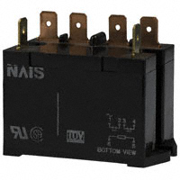
power relays
HE RELAYS
FEATURES
1. Excellent resistance to contact
welding
Owing to the pre-tension and kick-off
mechanism, the 1 Form A passes TV-15
and the 2 Form A passes TV-10.
2. High-capacity and long life
Contact
arrangement
Contact capacity
Electrical life
(at 20 times/min.)
Mechanical life
(at 180 times/min.)
1 Form A Plug-in type
RoHS compliant
1 Form A type 2 Form A type
30A
25A
2×10⁵
DC type: 107, AC type: 5×10⁶
3. Excellent surge resistance
Between contacts and coil, the surge
voltage is more than 10,000 V
(when surge waveform accords with
JEC-212-1981).
Protective construction:
• Dust cover type: Plug-in, TM and Screw
terminal types
• Flux-resistant type: PC board type
TYPICAL APPLICATIONS
1. Office equipment
Copiers, package air conditioners,
automatic vending machines.
2. Industrial equipment
Machine tools, molding equipment,
wrapping machines, food processing
equipment, etc.
3. Home appliances
Air conditioners, microwave ovens,
televisions, stereo systems, water
heaters and air heating equipment.
Single side stable type
HE 1 Form A, 2 Form A
Min. 8 mm
Plug-in, TM and
PC board type:
Screw terminal types:
Min. 2.5 mm .098 inch
Min. 3 mm .118 inch
Type
Insulation gap
Distance between contacts*
Breakdown
voltage
4. Compatible with all major safety
standards
UL, CSA, VDE and TÜV certified
5. Terminals are available
Between open contacts
Between contact and coil
2, 000 Vrms for 1 min.
5, 000 Vrms for 1 min.
* Reference value
CLASSIFICATION
Type
Operating funciton
Contact arrangement
PC board
1 Form A
Plug-in
1 Form A
2 Form A
TM
Single side stable
1 Form A
Screw terminal
2 Form A
1 Form A
2 Form A
ORDERING INFORMATION
HE
HE Relay
Contact arrangement
1a: 1 Form A (Single side stable type)
2a: 2 Form A (Single side stable type)
Pick-up voltage
N: 70% of nominal voltage
Terminals
Nil: Plug-in type
S: Screw terminal type
Q: TM type
P: PC board type
Nominal coil voltage
DC 6, 12, 24, 48, 100, 110 V
AC 12, 24, 48, 100 (100/120), 200 (200/240) V
2014.02
industrial.panasonic.com/ac/e/
–1–
© Panasonic Corporation 2014
ASCTB183E 201402-T
�HE
TYPES
1. PC board type (1 Form A, DC coil) (Single side stable type)
1 Form A
Part No.
HE1aN-P-DC6V
HE1aN-P-DC12V
HE1aN-P-DC24V
HE1aN-P-DC48V
HE1aN-P-DC100V
HE1aN-P-DC110V
Nominal coil voltage
6V DC
12V DC
24V DC
48V DC
100V DC
110V DC
Standard packing: Carton: 25 pcs.; Case: 100 pcs.
2. Plug-in type (Single side stable type)
Type
DC type
AC type
Nominal coil voltage
6V DC
12V DC
24V DC
48V DC
100V DC
110V DC
12V AC
24V AC
48V AC
100/120V AC
200/240V AC
1 Form A
Part No.
HE1aN-DC6V
HE1aN-DC12V
HE1aN-DC24V
HE1aN-DC48V
HE1aN-DC100V
HE1aN-DC110V
HE1aN-AC12V
HE1aN-AC24V
HE1aN-AC48V
HE1aN-AC100V
HE1aN-AC200V
2 Form A
Part No.
HE2aN-DC6V
HE2aN-DC12V
HE2aN-DC24V
HE2aN-DC48V
HE2aN-DC100V
HE2aN-DC110V
HE2aN-AC12V
HE2aN-AC24V
HE2aN-AC48V
HE2aN-AC100V
HE2aN-AC200V
1 Form A
Part No.
HE1aN-Q-DC6V
HE1aN-Q-DC12V
HE1aN-Q-DC24V
HE1aN-Q-DC48V
HE1aN-Q-DC100V
HE1aN-Q-DC110V
HE1aN-Q-AC12V
HE1aN-Q-AC24V
HE1aN-Q-AC48V
HE1aN-Q-AC100V
HE1aN-Q-AC200V
2 Form A
Part No.
HE2aN-Q-DC6V
HE2aN-Q-DC12V
HE2aN-Q-DC24V
HE2aN-Q-DC48V
HE2aN-Q-DC100V
HE2aN-Q-DC110V
HE2aN-Q-AC12V
HE2aN-Q-AC24V
HE2aN-Q-AC48V
HE2aN-Q-AC100V
HE2aN-Q-AC200V
1 Form A
Part No.
HE1aN-S-DC6V
HE1aN-S-DC12V
HE1aN-S-DC24V
HE1aN-S-DC48V
HE1aN-S-DC100V
HE1aN-S-DC110V
HE1aN-S-AC12V
HE1aN-S-AC24V
HE1aN-S-AC48V
HE1aN-S-AC100V
HE1aN-S-AC200V
2 Form A
Part No.
HE2aN-S-DC6V
HE2aN-S-DC12V
HE2aN-S-DC24V
HE2aN-S-DC48V
HE2aN-S-DC100V
HE2aN-S-DC110V
HE2aN-S-AC12V
HE2aN-S-AC24V
HE2aN-S-AC48V
HE2aN-S-AC100V
HE2aN-S-AC200V
Standard packing: Carton: 20 pcs.; Case: 100 pcs.
3. TM type (Single side stable type)
Type
DC type
AC type
Nominal coil voltage
6V DC
12V DC
24V DC
48V DC
100V DC
110V DC
12V AC
24V AC
48V AC
100/120V AC
200/240V AC
Standard packing: Carton: 20 pcs.; Case: 100 pcs.
4. Screw terminal type (Single side stable type)
Type
DC type
AC type
Nominal coil voltage
6V DC
12V DC
24V DC
48V DC
100V DC
110V DC
12V AC
24V AC
48V AC
100/120V AC
200/240V AC
Standard packing: Carton: 10 pcs.; Case: 50 pcs.
Note: The TM type of the screw terminals are also available.
* Terminal sockets available.
Panasonic Corporation Automation Controls Business Division
industrial.panasonic.com/ac/e/
–2–
© Panasonic Corporation 2014
ASCTB183E 201402-T
�HE
RATING
1. Coil data
1) AC coils
Nominal coil voltage
Pick-up voltage
(at 20°C 68°F)
Drop-out voltage
(at 20°C 68°F)
70%V or less of
nominal voltage
(Initial)
15%V or more of
nominal voltage
(Initial)
Pick-up voltage
(at 20°C 68°F)
Drop-out voltage
(at 20°C 68°F)
Nominal operating current
[±10%] (at 20°C 68°F)
Nominal operating power
138mA
1.7VA
74mA
39mA
18.7 to 2.1mA
9.1 to 10.8mA
1.8VA
1.9VA
1.9 to 2.7VA
1.8 to 2.6VA
12V AC
24V AC
48V AC
100/120V AC
200/240V AC
Max. applied voltage
(at 20°C 68°F)
110%V of
nominal voltage
2) DC coils
6V DC
Nominal operating
current
[±10%] (at 20°C 68°F)
320mA
12V DC
24V DC
48V DC
100V DC
110V DC
160mA
80mA
40mA
19mA
18mA
Nominal coil voltage
70%V or less of
nominal voltage
(Initial)
10%V or more of
nominal voltage
(Initial)
Coil resistance
[±10%] (at 20°C 68°F)
Nominal operating
power
18.8Ω
1.92W
75Ω
300Ω
1,200Ω
5,200Ω
6,300Ω
1.92W
1.92W
1.92W
1.92W
1.92W
Max. applied voltage
(at 55°C 131°F)
110%V of
nominal voltage
2. Specifications
Characteristics
Contact
Rating
Item
Contact material
Arrangement
Contact resistance (Initial)
Nominal switching capacity (resistive load)
Max. switching power
Max. switching voltage
Max. switching current
Nominal operating power
Min. switching capacity (Reference value)*1
Insulation resistance (Initial)
Specifications
AgSnO2 type
1 Form A
2 Form A
Max. 100 mΩ (By voltage drop 6 V DC 1A)
30A 277V AC
25A 277V AC
8,310VA
6,925VA
277V AC, 30V DC
30A
25A
DC: 1.92W, AC: 1.7 to 2.7VA
100mA 5V DC
Min. 1,000MΩ (at 500V DC) Measurement at same location as “Breakdown voltage” section.
Between open contacts
Between contact sets
Between contact and coil
Temperature rise (coil)
Surge breakdown voltage*2
(between contact and coil) (Initial)
Operate time (at nominal voltage)
2,000 Vrms for 1min (Detection current: 10mA.)
—
4,000 Vrms for 1min (Detection current: 10mA.)
5,000 Vrms for 1min (Detection current: 10mA.)
DC: Max. 60°C (at 55°C) (By resistive method), AC: Max. 65°C (at 55°C) (By resistive method)
Breakdown voltage
(Initial)
Electrical
characteristics
Release time (at nominal voltage)
Functional
Destructive
Functional
Vibration resistance
Destructive
Mechanical
Shock resistance
Mechanical
characteristics
Expected life
Conditions
Electrical (resistive load) (at 20 times/min.)
Conditions for operation, transport and storage*3
Max. operating speed
Unit weight
Min. 10,000V
Max. 30ms (excluding contact bounce time)
DC: Max.10ms (excluding contact bounce time, without diode),
AC: Max. 30ms (excluding contact bounce time)
Min. 98 m/s2 (Half-wave pulse of sine wave: 11 ms; detection time: 10µs.)
Min. 980 m/s2 (Half-wave pulse of sine wave: 6 ms.)
10 to 55 Hz at double amplitude of 1 mm (Detection time: 10µs.)
10 to 55 Hz at double amplitude of 1.5 mm
DC: Min. 107 (at 180 times/min.), AC: Min. 5×10⁶ (at 180 times/min.)
Min. 105 (25A 277V AC)
Min. 2×10⁵ (30A 250V AC)
Min. 2×10⁵ (20A 250V AC)
Ambient temperature: –50°C to +55°C –58°F to +131°F
Humidity: 5 to 85% R.H. (Not freezing and condensing at low temperature),
Air pressure: 86 to 106kPa
20 times/min. (at max. rating)
PC board type: approx. 80g 2.82oz, Plug-in type/TM type: approx. 90g 3.17oz,
Screw terminal type: approx. 120g 4.23oz
Notes: *1. This value can change due to the switching frequency, environmental conditions, and desired reliability level, therefore it is recommended to check this with the
actual load.
*2. Wave is standard shock voltage of ±1.2×50µs according to JEC-212-1981
*3. The upper limit of the ambient temperature is the maximum temperature that can satisfy the coil temperature rise value. Refer to Usage, transport and storage
conditions in NOTES.
Panasonic Corporation Automation Controls Business Division
industrial.panasonic.com/ac/e/
–3–
© Panasonic Corporation 2014
ASCTB183E 201402-T
�HE
REFERENCE DATA
1 Form A Type
1. Maximum switching power
2. Life curve
3. Coil temperature rise (DC type)
Measured portion: Inside the coil
Contact current: 30 A
1,000
AC resistive load
10
5
DC resistive load
1
0.5
70
500
Temperature rise, °C
50
30
20
No. of operations, ×104
Contact current, A
100
100
250 V AC resistive
30 V DC resistive
50
10
60
20°C
50 40°C
40
60°C
30
20
5
10
30
100
500 1,000
0
5
10
Contact voltage, V
15
20
25
30
0
35
100
110
120
Coil applied voltage, %V
Contact current, A
4. Ambient temperature characteristics
Tested sample: HE1aN-AC120V, 6 pcs.
Rate of
change, %
30
–50
–20
20
Pick-up
voltage
x-x
10
Drop-out
voltage
20 40
0
–10
60 80
Ambient
temperature, °C
–20
–30
2 Form A Type
1. Maximum switching power
2. Life curve
3. Coil temperature rise (DC type)
100
1,000
50
30
20
500
10
5
DC resistive load
70
60
Temperature rise, °C
AC resistive load
No. of operations, ×104
Contact current, A
Measured portion: Inside the coil
Contact current: 25 A
100
250 V AC resistive load
30 V DC resistive load
50
1
10
0.5
5
20°C
50 40°C
60°C
40
30
20
10
30
100
500 1,000
Contact voltage, V
0
5
10
15 20
25
30
Contact current, A
35
0
100
110
120
Coil applied voltage, %V
4. Ambient temperature characteristics
Rate of
change, %
Tested sample: HE2aN-AC120V, 6 pcs.
xx-
Pick-up
20 voltage
10
Drop-out
voltage
–50
–20
0
20 40
–10
60 80
Ambient
temperature, °C
–20
–30
Panasonic Corporation Automation Controls Business Division
industrial.panasonic.com/ac/e/
–4–
© Panasonic Corporation 2014
ASCTB183E 201402-T
�HE
DIMENSIONS (mm inch)
1. PC board type
1 Form A
CAD Data
The CAD data of the products with a
CAD Data
mark can be downloaded from: http://industrial.panasonic.com/ac/e/
External dimensions
Schematic (Bottom view)
Single side stable type
Single side stable type
33
1.299
38.0
1.496
1
4
6
5
PC board pattern (Bottom view)
24
.945
4.7
.185
8.4
.331
36.3
1.429
0.5
.020
4.7
.185
18.6
.732
4
.157
General tolerance: ±0.3 ±.012
2. Plug-in type
1 Form A
CAD Data
Tolerance: ±0.1 ±.004
External dimensions
Schematic (Bottom view)
Single side stable type
Single side stable type
36.4
1.433
2-4.5 dia.
2-.177 dia.
1
6.35
.250
4
6
5
R4
R.157 5
6
8.4 10.25
.331 .404
1
4
33
1.299
0.8
.031
6-2 dia. hole
6-.079 dia.
32
1.260
Panel cutout
40
1.575
50
1.969
#250 tab terminal
2-4.5±0.1 dia.
2-.177±.004 dia.
40±0.1
1.575±.004
10.4
.409
Tolerance: ±0.1 ±.004
35
1.378
3.5
.138
0.8
.031
General tolerance: ±0.3 ±.012
2 Form A
CAD Data
External dimensions
Schematic (Bottom view)
Single side stable type
Single side stable type
1
36.4
1.433
14.4
.567
2-4.5 dia.
2-.177 dia.
1
2
3
4
2
3
6
4
5
33
1.299
6
8.4 10.25
.331 .404
0.8
.031
6.35
.250
R4
R.157 5
Panel cutout
40
1.575
50
1.969
#250 tab terminal
2-4.5±0.1 dia.
2-.177±.004 dia.
40±0.1
1.575±.004
Tolerance: ±0.1 ±.004
10.4
.409
35
1.378
3.5
.138
0.8
.031
General tolerance: ±0.3 ±.012
Panasonic Corporation Automation Controls Business Division
industrial.panasonic.com/ac/e/
–5–
© Panasonic Corporation 2014
ASCTB183E 201402-T
�HE
3. TM type
External dimensions
CAD Data
Schematic (Bottom view)
Single side stable type
Single side stable type
1 Form A
2 Form A
47.6
1.874
36.4
1.433
14.4
.567
47.6
1.874
36.4
1.433
1
4.5
.177
33
1.299
40
1.575
50
1.969
60
2.362
8.4 10.25
.331 .404
6.35
.250
3
4
3
4
5
Panel cutout
2-4.5±0.1 dia.
2-.177±.004 dia.
47.6±0.1
1.874±.004
10.4
.409
35
1.378
2
6
#250 tab terminal
10.4
.409
5
2 Form A
R4
R.157 5
40
1.575
50
1.969
60
2.362
6.35
.250
0.8
.031
6
1
33
1.299
8.4 10.25
.331 .404
#250 tab terminal
3.5
.138
2
6
4
1 Form A
4.5
.177
R4
R.157 5
6
0.8
.031
1
4
1
Tolerance: ±0.1 ±.004
35
1.378
3.5
.138
0.8
.031
0.8
.031
General tolerance: ±0.3 ±.012
4. Screw terminal type
1 Form A
CAD Data
External dimensions
Schematic (Bottom view)
Single side stable type
Single side stable type
M4.5
M.177
2-4.5 dia.
2-.177 dia.
M3.5
M.138
51.0
2.008
40.0
1.575
14.4
.567
R4
R.157
33.5
1.319
50.0
1.969
17.5
.689
21.5
.846
16.5
.650
1
4
6
5
Panel cutout
2-4.5±0.1 dia.
2-.177±.004 dia.
40±0.1
1.575±.004
7.5
.295
Tolerance: ±0.1 ±.004
44.5
1.752
3.5
.138
0.8
.031
2 Form A
CAD Data
General tolerance: ±0.3 ±.012
External dimensions
Schematic (Bottom view)
Single side stable type
Single side stable type
M4.0
M.157
2-4.5 dia.
2-.177 dia.
M3.5
M.138
1
51.0
2.008
40.0
1.575
36.4
1.433
14.4
.567
R4
R.157
33.5
1.319
50.0
1.969
2
3
6
17.5
.689
21.5
.846
16.5
.650
4
5
Panel cutout
2-4.5±0.1 dia.
2-.177±.004 dia.
7.5
.295
40±0.1
1.575±.004
Tolerance: ±0.1 ±.004
44.5
1.752
3.5
.138
0.8
.031
Panasonic Corporation Automation Controls Business Division
industrial.panasonic.com/ac/e/
–6–
General tolerance: ±0.3 ±.012
© Panasonic Corporation 2014
ASCTB183E 201402-T
�HE
MOUNTING METHOD
1. Plug-in type
2. Screw terminal type
M4 screw
M4 screw
Washer
3. Allowable installation wiring size for
screw terminal types and terminal
sockets
Due to the UP terminals, it is possible to
either directly connect the wires or use
crimped terminal.
Washer
Faston No. 250
SAFETY STANDARDS
Item
1 Form A
2 Form A
UL/C-UL (Recognized)
File No.
Contact rating
E43028
30A 277V AC
30A 30V DC
1.5HP 125V AC
3HP 250V AC
E43028
25A 277V AC
25A 30V DC
1HP 125V AC
2HP 250V AC
CSA (Certified)
File No.
Contact rating
LR26550
30A 277V AC
etc.
30A 30V DC
1.5HP 125V AC
3HP 250V AC
LR26550
25A 277V AC
etc.
25A 30V DC
1HP 125V AC
2HP 250V AC
File No.
40006681
40006681
VDE (Certified)
Contact rating
30A 250V AC (cosφ =1.0)
30A 250V AC (cosφ =0.4)
5A 110V DC (0ms)
TV rating (UL/CSA)
File No.
Rating
UL
TV-15
E43028
TÜV (Certified)
File No.
Rating
B 11 04
30A 250V AC (cosφ =1.0)
13461 293 30A 250V AC (cosφ =0.4)
8A 110V DC (0ms)
25A 250V AC (cosφ =1.0)
25A 250V AC (cosφ =0.4)
5A 110V DC (0ms)
UL
E43028
B 11 04
25A 250V AC (cosφ =1.0)
13461 293 25A 250V AC (cosφ =0.4)
8A 110V DC (0ms)
TV-10
NOTES
1. For cautions for use, please read
“GENERAL APPLICATION
GUIDELINES” on page B-1.
2. The dust cover should not be
removed since doing so may alter the
characteristics.
3. Avoid use under severe
environmental conditions, such as
high humidity, organic gas or in dust,
oily locations and locations subjected
to extremely frequent shock or
vibrations.
4. When mounting, use spring
washers. Optimum fastening torque
ranges from 49 to 68.6 N·m (5 to 7
kgf·cm).
5. Firmly insert the receptacles so that
there is no slack or looseness. To
remove a receptacle, 19.6 to 39.2 N
(2 to 4 kg) of pulling strength is
required. Do not remove more than
one receptacle at one time. Always
remove one receptacle at a time and
pull it straight outwards.
6. When using the AC type, the operate
time due to the in-rush phase is 20 ms
or more. Therefore, it is necessary for
you to verify the characteristics for
your actual circuit.
Panasonic Corporation Automation Controls Business Division
industrial.panasonic.com/ac/e/
–7–
7. When using the push-on blocks for
the screw terminal type, use crimped
terminals and tighten the screw-down
terminals to the torque below.
M4.5 screw: 147 to 166.6 N⋅cm (15 to 17
kgf·cm)
M4 screw: 117.6 to 137 N·cm (12 to 14
kgf·cm)
M3.5 screw: 78.4 to 98 N·cm (8 to 10
kgf·cm)
© Panasonic Corporation 2014
ASCTB183E 201402-T
�Automation Controls Catalog
ACCESSORIES
HE RELAY
TERMINAL SOCKETS
FEATURES
1. Snap-in mounting to DIN rails is
possible
Can be inserted into 35 mm 1.378 inch
wide DIN rails. Removal is easy, too.
2. Sure and easy wiring
The use of UP terminals makes wiring
exceptionally easy and sure.
3. Hold-down clips can be stored in
main unit
Because the hold-down clips can be
stored in the main unit, there is no need
to remove them when, for example,
wiring is changed.
TYPES
No. of poles
For 1 Form A
For 2 Form A
Types
Single side stable type
Single side stable type
Part No.
JH1-SF
JH2-SF
Standard packing: Carton: 10 pcs.; Case: 50 pcs.
SPECIFICATIONS
Item
Arrangement
Max. continuous current
Breakdown voltage (initial)
Insulation resistance
Heat resistance
Specifications
1 Form A
2 Form A
30A 250V AC
20A 250V AC
2,000 Vrms for 1min (between terminals) (Detection current: 10mA.)
Min. 100MΩ (between poles)
150°C ±3°C 302°F ±37.4°F for 1 hour
Note: Do not insert or remove while powered on.
DIMENSIONS (mm inch)
The CAD data of the products with a
CAD Data
mark can be downloaded from: http://industrial.panasonic.com/ac/e/
1 Form A and 2 Form A types
External dimensions
CAD Data
M3.5×4 screw
M.138×4
Lot No.
11
.433
14.4
.567
11
.433
7
3
60
2.362
22
.866
2
8
9
.354
2-4.2 dia. hole
(or 2-M4 screw hole)
2-.165 dia. hole
(or 2-M.157 screw hole)
1
6
10.25
.404
4
.157
40
1.575
4
5
9
.354
Panel cutout
M4×4 screw
M.157×4
8.4
.331
9.2
.362
16
.630
Relay mounting diagram
23
.906
34
1.339
70
2.756
61
2.402
Note: The JH1-SF (1 Form A single side stable type) does not have receptacles (tooth rests) for numbers 2, 3, 7, and 8.
The JH2-SF (2 Form A single side stable type) does not have receptacles (tooth rests) for numbers 7 and 8.
2014.02
industrial.panasonic.com/ac/e/
–1–
© Panasonic Corporation 2014
ASCTB259E 201402-T
�HE Relay Terminal Sockets
MOUNTING METHOD
1. Relay mounting
2. Installing to a DIN rail
3. Removing from a DIN rail
Push
Flat-head screwdriver
NOTES
1. Be careful not to drop the relay. It is
made of heat-hardened resin and may
break.
2. Be sure to tighten the screw-down
terminals firmly. Loose terminals may
lead to the generation of heat.
3. When the 1 Form A is used in
situations covered by the Japanese
Electrical Appliance and Material
Control Law, the use of 5.5 mm2
cabling and 30 A current is not
allowed. Consequently, the circuit
should be less than 20 A.
4. When fixing the terminal socket with
screws, to avoid torque damage and
distortion, apply torque within the
ranges shown below.
M3.5 screws: 0.784 to 0.98 N·m (8 to 10
kgf·cm)
M4 screws: 1.176 to 1.37 N·m (12 to 14
kgf·cm)
Panasonic Corporation Automation Controls Business Division
industrial.panasonic.com/ac/e/
–2–
© Panasonic Corporation 2014
ASCTB259E 201402-T
�


 工商网监
湘ICP备2023018690号
工商网监
湘ICP备2023018690号
