NJM2380/A, NJM2390/A
ADJUSTABLE HIGH PRECISION SHUNT REGULATOR
■ GENERAL DESCRIPTION
The NJM2380/A and NJM2390/A are adjustable
high precision shunt regulators.
They are adapted for downsizing power supply
module, battery charger and others, because an
ultra mini package SOT23-5 is included in the
package line-up.
■ PACKAGE OUTLINE
■ FEATURES
● Operating Voltage
VREF to 18V
● High Precision Voltage Reference 2.465V±2%
2.465V±1% : A Version
● Mounted in Ultra Mini Package
SOT23-5
● Minimum External Parts
● Bipolar Technology
● Package Outline
DMP8, SOP8 JEDEC 150mil
SOT89-3, SOT23-5
NJM2380M/AM
( DMP8 )
NJM2380E/AE
( SOP8 )
NJM2380U/AU
NJM2390U/AU
( SOT89-3 )
NJM2380F/AF
( SOT23-5 )
■ PIN CONFIGURATION
PIN FUNCTION
NJM2380M/AM
NJM2380E/AE
1.
2.
3.
4.
5.
6.
7.
8.
CATHODE
NC
NC
NC
NC
ANODE
NC
REFERENCE
PIN FUNCTION
NJM2380F/AF
PIN FUNCTION
NC
ANODE
NC
CATHODE
REFERENCE
PIN FUNCTION
1. REFERENCE
2. ANODE
3. CATHODE
NJM2380U/AU
1.
2.
3.
4.
5.
1. CATHODE
2. ANODE
3. REFERENCE
NJM2390U/AU
■ BLOCK DIAGRAM
Ver.2017-07-13
-1-
�NJM2380/A, NJM2390/A
■ ABSOLUTE MAXIMUM RATINGS
PARAMETER
(Ta=25°C)
SYMBOL
RATINGS
UNIT
Cathode Voltage
VKA
+20
V
Continuous Cathode Current
IKA
-100 to 150
mA
Reference Input Current
IREF
-0.05 to 10
mA
Power Dissipation
PD
(DMP8)
300
(SOP8)
300
(SOT89)
350
(SOT23)
mW
200
Operating Temperature Range
TOPR
-40 to +85
°C
Storage Temperature Range
TSTG
-50 to +150
°C
■ RECOMMENDED OPERATING CONDITIONS
PARAMETER
SYMBOL
MIN.
TYP.
MAX.
UNIT
Cathode Voltage
VKA
VREF
-
18
V
Cathode Current
IK
1
100
mA
■ ELECTRICAL CHARACTERISTICS
PARAMETER
Reference Voltage
Reference Voltage
Change vs. Cathode
Voltage Change
(IK=10mA, Ta=25°C)
SYMBOL
VREF
VREF/VKA
CONDITIONS
MIN.
TYP.
MAX.
UNIT
VKA=VREF(*1)
2415
2465
2515
mV
VKA=VREF(*1), A Version
2440
2465
2490
│VREF│≤VKA≤10V(*2)
-
±1.4
±2.7
mV/V
10≤VKA≤18V(*2)
-
±1
±2
mV/V
Reference Input Current
IREF
R=10kΩ, R2=∞(*2)
-
2
4
μA
Minimum Input Current
IMIN
VKA=VREF(*1)
-
0.4
1.0
mA
Cathode Current (Off Cond.)
IOFF
VKA=18V, VREF=0V(*3)
-
0.1
1.0
μA
VKA=VREF, f≤1kHz
1mA≤IK≤100mA(*1)
-
0.2
-
Ω
Dynamic Impedance
│ZKA│
■ TEMPERATURE CHARACTERISTICS
PARAMETER
SYMBOL
(IK=10mA, Ta=-20 to +85°C)
CONDITIONS
MIN.
TYP.
MAX.
UNIT
Reference Voltage Change
ΔVREF
VKA=VREF(*1)
-
8
17
mV
Reference Input Current Change
ΔIREF
R1=10kΩ, R2=∞(*2)
-
0.4
1.2
μA
The "Reference Voltage Change" and "Reference Input Current Change" is tested to using some samples of the first five lots. These
"TEMPERATURE CHARACTERISTICS" are not guaranteed.
│VREF│…Reference voltage includes error.
(*1) : TEST CIRCUIT 1 (Fig.1)
(*2) : TEST CIRCUIT 2 (Fig.2)
(*3) : TEST CIRCUIT 3 (Fig.3)
-2-
Ver.2017-07-13
�NJM2380/A, NJM2390/A
■ TEST CIRCUIT
1, VKA=VREF
2, VKA>VREF
VO=VKA=VREF● 1
VO=VKA=VREF
(Fig.1)
3, IOFF
R1
+IREF●R1
R2
(Fig.2)
(Fig.3)
■ POWER DISSIPATION VS. AMBIENT TEMPERATURE
Power Dissipation PD (mW)
500
400
SOT89
300
DMP8/SOP8
200
SOT23(MTP5)
100
0
-50
-25
0
25
50
75
100
125
150
Ambient Temperature Ta (°C)
Ver.2017-07-13
-3-
�NJM2380/A, NJM2390/A
■ TYPICAL CHARACTERISTICS
Reference Voltage
Reference Voltage
(VKA=VREF,Ta=25°C)
(IK=10mA,R1=Variable,R2=2.5kΩ,Ta=25°C)
Reference Input Current
Reference Voltage
(IK=10mA,R1=10kΩ,R2=∞)
(VKA=VREF,IK=10mA)
Dynamic Inpedance
(IK=10mA,Ta=25°C)
-4-
Ver.2017-07-13
�NJM2380/A, NJM2390/A
■ TYPICAL CHARACTERISTICS
Safety Operating Boundary Condition
Safety Operating Boundary Condition
Test Circuit
(Rin=30, Ta=25oC)
100
(mA)
Aluminum Electrolytic Capacitor
V =V
80
REF
Rin=30
, 5V
VKA
Cathode Current I
K
KA
60
IK
Stable Operaion Region
V+
40
COUT
Unstable Operaion Region
20
0
0.1
1
Output Capacitor C OUT (F)
10
Note) Oscillation might occur while operating within the range of safety curve.
So that, it is necessary to make ample margins by taking considerations of
fluctuation of the device.
Safety Operating Boundary Condition
(Rin=30, Ta=25oC)
Ceramic Capacitor
V =V
KA
REF
V =5V
80
KA
Cathode Current I
K
(mA)
100
60
Stable
Operaion
40
Region
20
0
0.01
Unstable
Operaion
Region
0.1
1
Output Capacitor C OUT (F)
10
[CAUTION]
The specifications on this databook are only
given for information , without any guarantee
as regards either mistakes or omissions. The
application circuits in this databook are
described only to show representative usages
of the product and not intended for the
guarantee or permission of any right including
the industrial rights.
Ver.2017-07-13
-5-
�
很抱歉,暂时无法提供与“NJM2390U-TE1”相匹配的价格&库存,您可以联系我们找货
免费人工找货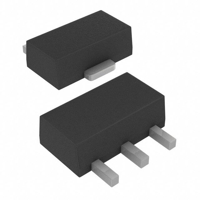


 工商网监
湘ICP备2023018690号
工商网监
湘ICP备2023018690号
