INTEGRATED CIRCUITS
DATA SHEET
74ALVC08
Quad 2-input AND gate
Product specification
Supersedes data of 2003 Feb 04
2003 May 16
�Philips Semiconductors
Product specification
Quad 2-input AND gate
74ALVC08
FEATURES
DESCRIPTION
• Wide supply voltage range from 1.65 to 3.6 V
The 74ALVC08 is a high-performance, low-power,
low-voltage, Si-gate CMOS device and superior to most
advanced CMOS compatible TTL families.
• 3.6 V tolerant inputs/outputs
• CMOS low power consumption
Schmitt-trigger action at all inputs makes the circuit
tolerant for slower input rise and fall times.
• Direct interface with TTL levels (2.7 to 3.6 V)
• Power-down mode
The 74ALVC08 provides the 2-input AND function.
• Latch-up performance exceeds 250 mA
• Complies with JEDEC standard:
JESD8-7 (1.65 to 1.95 V)
JESD8-5 (2.3 to 2.7 V)
JESD8B/JESD36 (2.7 to 3.6 V).
• ESD protection:
HBM EIA/JESD22-A114-A exceeds 2000 V
MM EIA/JESD22-A115-A exceeds 200 V.
QUICK REFERENCE DATA
GND = 0 V; Tamb = 25 °C.
SYMBOL
tPHL/tPLH
PARAMETER
propagation delay nA, nB to nY
CI
input capacitance
CPD
power dissipation capacitance per buffer
CONDITIONS
VCC = 1.8 V; CL = 30 pF; RL = 1 kΩ
UNIT
2.7
ns
VCC = 2.5 V; CL = 30 pF; RL = 500 Ω 1.9
ns
VCC = 2.7 V; CL = 50 pF; RL = 500 Ω 2.2
ns
VCC = 3.3 V; CL = 50 pF; RL = 500 Ω 2.0
ns
3.5
pF
24
pF
VCC = 3.3 V; notes 1 and 2
Notes
1. CPD is used to determine the dynamic power dissipation (PD in µW).
PD = CPD × VCC2 × fi × N + Σ(CL × VCC2 × fo) where:
fi = input frequency in MHz;
fo = output frequency in MHz;
CL = output load capacitance in pF;
VCC = supply voltage in Volts;
N = total load switching outputs;
Σ(CL × VCC2 × fo) = sum of the outputs.
2. The condition is VI = GND to VCC.
2003 May 16
TYPICAL
2
�Philips Semiconductors
Product specification
Quad 2-input AND gate
74ALVC08
ORDERING INFORMATION
PACKAGE
TYPE NUMBER
TEMPERATURE
RANGE
PINS
PACKAGE
MATERIAL
CODE
74ALVC08D
−40 to +85 °C
14
SO14
plastic
SOT108-1
74ALVC08PW
−40 to +85 °C
14
TSSOP14
plastic
SOT402-1
74ALVC08BQ
−40 to +85 °C
14
DHVQFN14
plastic
SOT762-1
FUNCTION TABLE
See note 1.
INPUT
OUTPUT
nA
nB
nY
L
L
L
L
H
L
H
L
L
H
H
H
Note
1. H = HIGH voltage level;
L = LOW voltage level.
PINNING
PIN
SYMBOL
DESCRIPTION
1
1A
data input
2
1B
data input
3
1Y
data output
1A
1
14 VCC
4
2A
data input
1B
2
13 4B
5
2B
data input
1Y
3
12 4A
6
2Y
data output
2A
4
7
GND
ground (0 V)
2B
5
10 3B
8
3Y
data output
9
3A
data input
2Y
6
9
10
3B
data input
GND
7
8 3Y
11
4Y
data output
12
4A
data input
13
4B
data input
14
VCC
supply voltage
2003 May 16
handbook, halfpage
08
11 4Y
3A
MNA220
Fig.1 Pin configuration SO14 and TSSOP14.
3
�Philips Semiconductors
Product specification
Quad 2-input AND gate
handbook, halfpage
1A
VCC
1
14
74ALVC08
1B
2
13
4B
1Y
3
12
4A
2A
4
11
4Y
2B
5
10
3B
2Y
6
9
3A
GND(1)
Top view
7
8
GND
3Y
handbook, halfpage
A
Y
B
MNA221
MNA950
(1) The die substrate is attached to this pad using conductive die
attach material. It can not be used as a supply pin or input.
Fig.2 Pin configuration DHVQFN14.
Fig.3 Logic diagram (one gate).
handbook, halfpage
1
&
3
&
6
&
8
&
11
2
handbook, halfpage
1
1A
2
1B
4
2A
5
2B
9
3A
10
3B
12
4A
13
4B
1Y
3
4
2Y
6
5
3Y
8
9
10
4Y
11
12
MNA222
13
MNA223
Fig.4 Function diagram.
2003 May 16
Fig.5 IEC logic symbol.
4
�Philips Semiconductors
Product specification
Quad 2-input AND gate
74ALVC08
RECOMMENDED OPERATING CONDITIONS
SYMBOL
PARAMETER
CONDITIONS
MIN.
MAX.
UNIT
VCC
supply voltage
1.65
3.6
V
VI
input voltage
0
3.6
V
VO
output voltage
VCC = 1.65 to 3.6 V
0
VCC
V
VCC = 0 V; Power-down mode
0
3.6
V
Tamb
operating ambient temperature
−40
+85
°C
tr, tf
input rise and fall times
VCC = 1.65 to 2.7 V
0
20
ns/V
VCC = 2.7 to 3.6 V
0
10
ns/V
LIMITING VALUES
In accordance with the Absolute Maximum Rating System (IEC 60134); voltages are referenced to GND (ground = 0 V).
SYMBOL
PARAMETER
VCC
supply voltage
IIK
input diode current
VI
input voltage
IOK
output diode current
VO
output voltage
IO
output source or sink current
CONDITIONS
VI < 0
VO > VCC or VO < 0
MIN.
MAX.
UNIT
−0.5
+4.6
V
−
−50
mA
−0.5
+4.6
V
−
±50
mA
notes 1 and 2
−0.5
VCC + 0.5 V
Power-down mode; note 2
−0.5
+4.6
V
VO = 0 to VCC
−
±50
mA
ICC, IGND
VCC or GND current
−
±100
mA
Tstg
storage temperature
−65
+150
°C
Ptot
power dissipation
−
500
mW
Tamb = −40 to +85 °C; note 3
Notes
1. The input and output voltage ratings may be exceeded if the input and output current ratings are observed.
2. When VCC = 0 V (Power-down mode), the output voltage can be 3.6 V in normal operation.
3. For SO14 packages: above 70 °C derate linearly with 8 mW/K.
For TSSOP14 packages: above 60 °C derate linearly with 5.5 mW/K.
For DHVQFN14 packages: above 60 °C derate linearly with 4.5 mW/K.
2003 May 16
5
�Philips Semiconductors
Product specification
Quad 2-input AND gate
74ALVC08
DC CHARACTERISTICS
At recommended operating conditions; voltages are referenced to GND (ground = 0 V).
TEST CONDITIONS
SYMBOL
PARAMETER
MIN.
OTHER
TYP.(1)
MAX.
UNIT
VCC (V)
Tamb = −40 to +85 °C
VIH
VIL
VOL
VOH
HIGH-level input voltage
HIGH-level output
voltage
−
V
1.7
−
−
V
2
−
−
V
2.7 to 3.6
1.65 to 1.95 −
−
0.35 × VCC V
2.3 to 2.7
−
−
0.7
V
2.7 to 3.6
−
−
0.8
V
IO = 100 µA
1.65 to 3.6
−
−
0.2
V
IO = 6 mA
1.65
−
0.11
0.3
V
IO = 12 mA
2.3
−
0.17
0.4
V
IO = 18 mA
2.3
−
0.25
0.6
V
IO = 12 mA
2.7
−
0.16
0.4
V
IO = 18 mA
3.0
−
0.23
0.4
V
IO = 24 mA
3.0
−
0.30
0.55
V
1.65 to 3.6
VCC − 0.2
−
−
V
LOW-level input voltage
LOW-level output
voltage
1.65 to 1.95 0.65 × VCC −
2.3 to 2.7
VI = VIH or VIL
VI = VIH or VIL
IO = −100 µA
IO = −6 mA
1.65
1.25
1.51
−
V
IO = −12 mA
2.3
1.8
2.10
−
V
IO = −18 mA
2.3
1.7
2.01
−
V
IO = −12 mA
2.7
2.2
2.53
−
V
IO = −18 mA
3.0
2.4
2.76
−
V
IO = −24 mA
3.0
2.2
2.68
−
V
ILI
input leakage current
VI = 3.6 V or GND
3.6
−
±0.1
±5
µA
Ioff
power OFF leakage
current
VI or VO = 3.6 V
0.0
−
±0.1
±10
µA
ICC
quiescent supply
current
VI = VCC or GND; IO = 0 3.6
−
0.2
20
µA
∆ICC
additional quiescent
supply current per input
pin
VI = VCC − 0.6 V; IO = 0
−
5
750
µA
Note
1. All typical values are measured at Tamb = 25 °C.
2003 May 16
6
3.0 to 3.6
�Philips Semiconductors
Product specification
Quad 2-input AND gate
74ALVC08
AC CHARACTERISTICS
TEST CONDITIONS
SYMBOL
PARAMETER
MIN.
WAVEFORMS
TYP.(1)
MAX.
UNIT
VCC (V)
Tamb = −40 to +85 °C
tPHL/tPLH
propagation delay
nA, nB to nY
see Figs 6 and 7
1.65 to 1.95
1.2
2.7
5.3
ns
2.3 to 2.7
1.0
1.9
3.2
ns
−
2.2
3.0
ns
3.0 to 3.6
1.2
2.0
2.9
ns
tPHL
tPLH
2.7
Note
1. All typical values are measured at Tamb = 25 °C.
AC WAVEFORMS
handbook, halfpage
VI
VM
nA, nB input
GND
VOH
VM
nY output
VOL
MNA224
INPUT
VCC
VM
VI
tr = tf
1.65 to 1.95 V
0.5 × VCC
VCC
≤ 2.0 ns
2.3 to 2.7 V
0.5 × VCC
VCC
≤ 2.0 ns
2.7 V
1.5 V
2.7 V
≤ 2.5 ns
3.0 to 3.6 V
1.5 V
2.7 V
≤ 2.5 ns
Fig.6 Inputs nA, nB to output nY propagation delay times.
2003 May 16
7
�Philips Semiconductors
Product specification
Quad 2-input AND gate
74ALVC08
VEXT
handbook, full pagewidth
VCC
PULSE
GENERATOR
VI
RL
VO
D.U.T.
CL
RT
RL
MNA616
VCC
VI
CL
RL
VEXT
tPLH/tPHL
tPZH/tPHZ
tPZL/tPLZ
1.65 to 1.95 V
VCC
30 pF
1 kΩ
open
GND
2 × VCC
2.3 to 2.7 V
VCC
30 pF
500 Ω
open
GND
2 × VCC
2.7 V
2.7 V
50 pF
500 Ω
open
GND
6V
3.0 to 3.6 V
2.7 V
50 pF
500 Ω
open
GND
6V
Definitions for test circuit:
RL = Load resistor.
CL = Load capacitance including jig and probe capacitance.
RT = Termination resistance should be equal to the output impedance Zo of the pulse generator.
Fig.7 Load circuitry for switching times.
2003 May 16
8
�Philips Semiconductors
Product specification
Quad 2-input AND gate
74ALVC08
PACKAGE OUTLINES
SO14: plastic small outline package; 14 leads; body width 3.9 mm
SOT108-1
D
E
A
X
c
y
HE
v M A
Z
8
14
Q
A2
A
(A 3)
A1
pin 1 index
θ
Lp
1
L
7
e
detail X
w M
bp
0
2.5
5 mm
scale
DIMENSIONS (inch dimensions are derived from the original mm dimensions)
UNIT
A
max.
A1
A2
A3
bp
c
D (1)
E (1)
e
HE
L
Lp
Q
v
w
y
Z (1)
mm
1.75
0.25
0.10
1.45
1.25
0.25
0.49
0.36
0.25
0.19
8.75
8.55
4.0
3.8
1.27
6.2
5.8
1.05
1.0
0.4
0.7
0.6
0.25
0.25
0.1
0.7
0.3
0.010 0.057
0.004 0.049
0.01
0.019 0.0100 0.35
0.014 0.0075 0.34
0.16
0.15
0.05
0.028
0.024
0.01
0.01
0.004
0.028
0.012
inches 0.069
0.244
0.039
0.041
0.228
0.016
θ
Note
1. Plastic or metal protrusions of 0.15 mm (0.006 inch) maximum per side are not included.
REFERENCES
OUTLINE
VERSION
IEC
JEDEC
SOT108-1
076E06
MS-012
2003 May 16
JEITA
EUROPEAN
PROJECTION
ISSUE DATE
99-12-27
03-02-19
9
o
8
0o
�Philips Semiconductors
Product specification
Quad 2-input AND gate
74ALVC08
TSSOP14: plastic thin shrink small outline package; 14 leads; body width 4.4 mm
SOT402-1
E
D
A
X
c
y
HE
v M A
Z
8
14
Q
(A 3)
A2
A
A1
pin 1 index
θ
Lp
L
1
7
detail X
w M
bp
e
0
2.5
5 mm
scale
DIMENSIONS (mm are the original dimensions)
UNIT
A
max.
A1
A2
A3
bp
c
D (1)
E (2)
e
HE
L
Lp
Q
v
w
y
Z (1)
θ
mm
1.1
0.15
0.05
0.95
0.80
0.25
0.30
0.19
0.2
0.1
5.1
4.9
4.5
4.3
0.65
6.6
6.2
1
0.75
0.50
0.4
0.3
0.2
0.13
0.1
0.72
0.38
8
0o
Notes
1. Plastic or metal protrusions of 0.15 mm maximum per side are not included.
2. Plastic interlead protrusions of 0.25 mm maximum per side are not included.
OUTLINE
VERSION
SOT402-1
2003 May 16
REFERENCES
IEC
JEDEC
JEITA
EUROPEAN
PROJECTION
ISSUE DATE
99-12-27
03-02-18
MO-153
10
o
�Philips Semiconductors
Product specification
Quad 2-input AND gate
74ALVC08
DHVQFN14: plastic dual in-line compatible thermal enhanced very thin quad flat package; no leads;
SOT762-1
14 terminals; body 2.5 x 3 x 0.85 mm
A
B
D
A
A1
E
c
detail X
terminal 1
index area
terminal 1
index area
C
e1
e
2
6
y
y1 C
v M C A B
w M C
b
L
1
7
Eh
e
14
8
13
9
Dh
X
0
2.5
5 mm
scale
DIMENSIONS (mm are the original dimensions)
UNIT
A(1)
max.
A1
b
c
D (1)
Dh
E (1)
Eh
e
e1
L
v
w
y
y1
mm
1
0.05
0.00
0.30
0.18
0.2
3.1
2.9
1.65
1.35
2.6
2.4
1.15
0.85
0.5
2
0.5
0.3
0.1
0.05
0.05
0.1
Note
1. Plastic or metal protrusions of 0.075 mm maximum per side are not included.
REFERENCES
OUTLINE
VERSION
IEC
JEDEC
JEITA
SOT762-1
---
MO-241
---
2003 May 16
11
EUROPEAN
PROJECTION
ISSUE DATE
02-10-17
03-01-27
�Philips Semiconductors
Product specification
Quad 2-input AND gate
74ALVC08
To overcome these problems the double-wave soldering
method was specifically developed.
SOLDERING
Introduction to soldering surface mount packages
If wave soldering is used the following conditions must be
observed for optimal results:
This text gives a very brief insight to a complex technology.
A more in-depth account of soldering ICs can be found in
our “Data Handbook IC26; Integrated Circuit Packages”
(document order number 9398 652 90011).
• Use a double-wave soldering method comprising a
turbulent wave with high upward pressure followed by a
smooth laminar wave.
There is no soldering method that is ideal for all surface
mount IC packages. Wave soldering can still be used for
certain surface mount ICs, but it is not suitable for fine pitch
SMDs. In these situations reflow soldering is
recommended.
• For packages with leads on two sides and a pitch (e):
– larger than or equal to 1.27 mm, the footprint
longitudinal axis is preferred to be parallel to the
transport direction of the printed-circuit board;
– smaller than 1.27 mm, the footprint longitudinal axis
must be parallel to the transport direction of the
printed-circuit board.
Reflow soldering
Reflow soldering requires solder paste (a suspension of
fine solder particles, flux and binding agent) to be applied
to the printed-circuit board by screen printing, stencilling or
pressure-syringe dispensing before package placement.
The footprint must incorporate solder thieves at the
downstream end.
• For packages with leads on four sides, the footprint must
be placed at a 45° angle to the transport direction of the
printed-circuit board. The footprint must incorporate
solder thieves downstream and at the side corners.
Several methods exist for reflowing; for example,
convection or convection/infrared heating in a conveyor
type oven. Throughput times (preheating, soldering and
cooling) vary between 100 and 200 seconds depending
on heating method.
During placement and before soldering, the package must
be fixed with a droplet of adhesive. The adhesive can be
applied by screen printing, pin transfer or syringe
dispensing. The package can be soldered after the
adhesive is cured.
Typical reflow peak temperatures range from
215 to 250 °C. The top-surface temperature of the
packages should preferably be kept:
• below 220 °C for all the BGA packages and packages
with a thickness ≥ 2.5mm and packages with a
thickness
很抱歉,暂时无法提供与“74ALVC08PW,112”相匹配的价格&库存,您可以联系我们找货
免费人工找货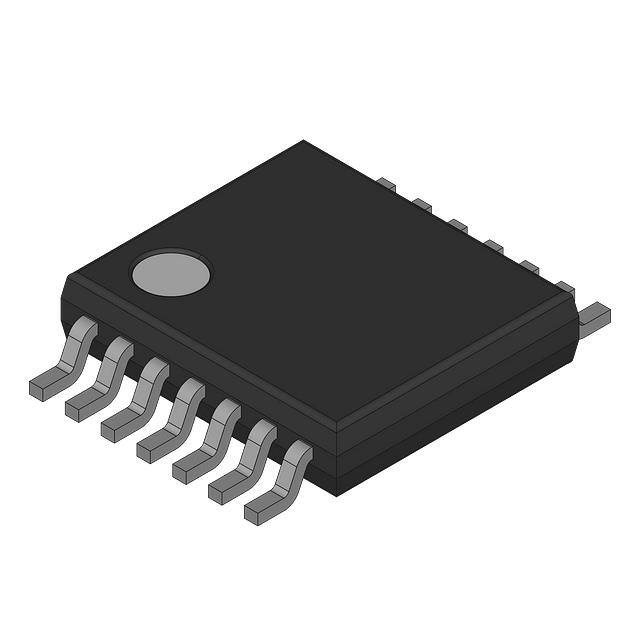


 工商网监
湘ICP备2023018690号
工商网监
湘ICP备2023018690号
