Archived by Freescale Semiconductor, Inc., 2009
Freescale Semiconductor
Technical Data
MC14578
Rev 2, 05/2005
The MC14578 is an analog building block consisting of a very-high input
impedance comparator. The voltage follower allows monitoring the noninverting
input of the comparator without loading.
Four enhancement-mode MOSFETs are also included on chip. These FETs
can be externally configured as open-drain or totem-pole outputs. The drains
have on-chip static-protecting diodes. Therefore, the output voltage must be
maintained between VSS and VDD.
The chip requires one external component. A 3.9 MΩ ±10% resistor must be
connected from the Rbias pin to VDD. This circuit is designed to operate in smoke
detector systems that comply with UL217 and UL268 specifications.
MC14578
CMOS
MICRO-POWER COMPARATOR
PLUS VOLTAGE FOLLOWER
Features
•
•
•
•
•
•
Applications:
Pulse Shapers
Line-Powered Smoke Detectors
Threshold Detectors
Liquid/Moisture Sensors
Low-Battery Detectors
CO Detector and Micro Interface
Operating Voltage Range: 3.5 to 14 V
Operating Temperature Range: -30° to 70°C
Input Current (IN + Pin): ±1 pA @ 25°C (DIP Only)
Quiescent Current: 10 μA @ 25°C
Electrostatic Discharge (ESD) Protection Circuitry on All Pins
ORDERING INFORMATION
Device
Temperature
Range
Case No.
Package
MC14578P
-30° to 70°C
648-08
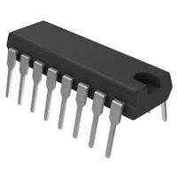
Plastic Dip
© Freescale Semiconductor, Inc., 2005. All rights reserved.
P SUFFIX
PLASTIC DIP
CASE 648-08
VDD
1
16
NC
Comp OUT
2
15
IN +
IN A
3
14
NC
IN B
4
13
Buff OUT
OUT A
OUT B
5
12
IN–
6
11
Rbias
IN C
7
10
OUT C1
8
9
VSS
OUT C2
Figure 1. Pin Connections
Archive Information
Archive Information
CMOS
Micro-Power Comparator plus
Voltage Follower
�Archived by Freescale Semiconductor, Inc., 2009
IN +
15
IN – 12
+
2
Comp
Comp OUT
IN A
3
–
5
Rbias 11
Bias
Ckt
OUT A
6
+
13
Buff
Buff OUT
IN B
9
OUT C2
IN C 7
OUT B
8
OUT C1
4
Pin 1 = VDD
Pin 10 = VSS
Pin 14, 16 = No Connection
Figure 2. Block Diagram
Table 1. Maximum Ratings(1)
(Voltages Referenced to VSS)
Symbol
Value
Unit
DC Supply Voltage
Rating
VDD
-0.5 to +14
V
DC Input Voltage
Vin
-0.5 to VDD +0.5
V
DC Output Voltage
Vout
-0.5 to VDD +0.5
V
DC Input Current, Except IN +
Iin
±10
mA
DC Output Current, IN +
Iin
±1.0
mA
DC Output Current, per Pin
Iout
±25
mA
DC Supply Current, VDD and VSS Pins
IDD
±50
mA
Power Dissipation, per Package
PD
500
mW
Storage Temperature
Tstg
-65 to + 150
°C
TL
260
°C
Lead Temperature (10-Second Soldering)
1. Maximum Ratings are those values beyond which damage to the device may occur. This device contains protection circuitry to guard against
damage due to high static voltages or electric fields. However, precautions must be taken to avoid applications of any voltage higher than
maximum rated voltages to this high-impedance circuit. For proper operation, Vin and Vout should be constrained to the range VSS ≤ (Vin or
Vout) ≤ VDD. Unused inputs must always be tied to an appropriate logic voltage level (e.g., either VSS or VDD). Unused outputs must be left
open.
MC14578
2
Sensors
Freescale Semiconductor
Archive Information
Archive Information
–
�Archived by Freescale Semiconductor, Inc., 2009
Archive Information
Characteristic
Symbol
Test Condition
VDD
VDC
Guaranteed
Limit
Unit
—
3.5 to 14.0
V
Power Supply Voltage Range
VDD
Maximum Low-Level Input Voltage, MOSFETs
Wired as Inverters; i.e., IN A tied to IN B, OUT A to
OUT B, OUT C1 to OUT C2
VIL
Vout = 9.0 V, IIoutI
很抱歉,暂时无法提供与“MC14578P”相匹配的价格&库存,您可以联系我们找货
免费人工找货