MJD5731
High Voltage PNP Silicon
Power Transistors
Designed for line operated audio output amplifier, SWITCHMODE
power supply drivers and other switching applications.
Features
http://onsemi.com
• PNP Complements to the MJD47 thru MJD50 Series
• Epoxy Meets UL 94 V−0 @ 0.125 in
• These Devices are Pb−Free and are RoHS Compliant
MAXIMUM RATINGS
Rating
SILICON
POWER TRANSISTORS
1.0 AMPERE
350 VOLTS, 15 WATTS
Symbol
Max
Unit
VCEO
350
Vdc
VEB
5
Vdc
IC
1.0
Adc
Collector Current − Peak
ICM
3.0
Adc
Total Power Dissipation
@ TC = 25°C
Derate above 25°C
PD
15
0.12
W
W/°C
Total Power Dissipation (Note 1)
@ TA = 25°C
Derate above 25°C
PD
1.56
0.0125
W
W/°C
Unclamped Inductive Load Energy
(See Figure 10)
E
20
mJ
TJ, Tstg
−55 to +150
°C
1 2
ESD − Human Body Model
HBM
3B
V
ESD − Machine Model
MM
C
V
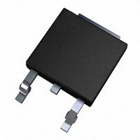
DPAK
CASE 369C
STYLE 1
Collector−Emitter Voltage
Emitter−Base Voltage
Collector Current − Continuous
Operating and Storage Junction
Temperature Range
COLLECTOR
2, 4
1
BASE
3
EMITTER
4
3
Stresses exceeding Maximum Ratings may damage the device. Maximum
Ratings are stress ratings only. Functional operation above the Recommended
Operating Conditions is not implied. Extended exposure to stresses above the
Recommended Operating Conditions may affect device reliability.
1. These ratings are applicable when surface mounted on the minimum pad
sizes recommended.
MARKING DIAGRAM
AYWW
J
5731G
THERMAL CHARACTERISTICS
Symbol
Max
Unit
Thermal Resistance, Junction−to−Case
Characteristic
RqJC
8.33
°C/W
Thermal Resistance, Junction−to−Ambient
(Note 2)
RqJA
80
°C/W
TL
260
°C
Lead Temperature for Soldering
2. These ratings are applicable when surface mounted on the minimum pad
sizes recommended.
A
Y
WW
J5731
G
= Assembly Location
= Year
= Work Week
= Device Code
= Pb−Free Package
ORDERING INFORMATION
Device
MJD5731T4G
Package
Shipping†
DPAK
(Pb−Free)
2500/Tape & Reel
†For information on tape and reel specifications,
including part orientation and tape sizes, please
refer to our Tape and Reel Packaging Specifications
Brochure, BRD8011/D.
© Semiconductor Components Industries, LLC, 2013
August, 2013 − Rev. 5
1
Publication Order Number:
MJD5731/D
�MJD5731
ÎÎÎÎÎÎÎÎÎÎÎÎÎÎÎÎÎÎÎÎÎÎÎÎÎÎÎÎÎÎÎÎÎÎÎÎÎ
ÎÎÎÎÎÎÎÎÎÎÎÎÎÎÎÎÎÎÎÎÎÎÎÎÎÎÎÎÎÎÎÎÎÎÎÎÎ
ÎÎÎÎÎÎÎÎÎÎÎÎÎÎÎÎÎÎÎÎÎÎÎÎÎÎÎÎÎÎÎÎÎ
ÎÎÎÎÎÎÎÎÎÎÎÎÎÎÎÎÎÎÎÎÎÎÎÎÎÎÎÎÎÎÎÎÎ
ÎÎÎÎÎÎÎÎÎÎÎÎÎÎÎÎÎÎ
ÎÎÎÎÎ
ÎÎÎÎÎ
ÎÎÎÎÎ
ÎÎÎÎ
ÎÎÎÎÎÎÎÎÎÎÎÎÎÎÎÎÎÎÎÎÎÎÎÎÎÎÎÎÎÎÎÎÎÎÎÎÎ
ÎÎÎÎÎÎÎÎÎÎÎÎÎÎÎÎÎÎÎÎÎÎÎÎÎÎÎÎÎÎÎÎÎÎÎÎÎ
ÎÎÎÎÎÎÎÎÎÎÎÎÎÎÎÎÎÎÎÎÎÎÎÎÎÎÎÎÎÎÎÎÎÎÎÎÎ
ÎÎÎÎÎÎÎÎÎÎÎÎÎÎÎÎÎÎÎÎÎÎÎÎÎÎÎÎÎÎÎÎÎÎÎÎÎ
ÎÎÎÎÎÎÎÎÎÎÎÎÎÎÎÎÎÎÎÎÎÎÎÎÎÎÎÎÎÎÎÎÎÎÎÎÎ
ÎÎÎÎÎÎÎÎÎÎÎÎÎÎÎÎÎÎ
ÎÎÎÎÎ
ÎÎÎÎÎ
ÎÎÎÎÎ
ÎÎÎÎ
ÎÎÎÎÎÎÎÎÎÎÎÎÎÎÎÎÎÎÎÎÎÎÎÎÎÎÎÎÎÎÎÎÎÎÎÎÎ
ÎÎÎÎÎÎÎÎÎÎÎÎÎÎÎÎÎÎÎÎÎÎÎÎÎÎÎÎÎÎÎÎÎ
ÎÎÎÎÎÎÎÎÎÎÎÎÎÎÎÎÎÎÎÎÎÎÎÎÎÎÎÎÎÎÎÎÎ
ÎÎÎÎÎÎÎÎÎÎÎÎÎÎÎÎÎÎ
ÎÎÎÎÎ
ÎÎÎÎÎ
ÎÎÎÎÎ
ÎÎÎÎ
ÎÎÎÎÎÎÎÎÎÎÎÎÎÎÎÎÎÎÎÎÎÎÎÎÎÎÎÎÎÎÎÎÎÎÎÎÎ
ÎÎÎÎÎÎÎÎÎÎÎÎÎÎÎÎÎÎÎÎÎÎÎÎÎÎÎÎÎÎÎÎÎÎÎÎÎ
ÎÎÎÎÎÎÎÎÎÎÎÎÎÎÎÎÎÎÎÎÎÎÎÎÎÎÎÎÎÎÎÎÎÎÎÎÎ
ÎÎÎÎÎÎÎÎÎÎÎÎÎÎÎÎÎÎ
ÎÎÎÎÎ
ÎÎÎÎÎ
ÎÎÎÎÎ
ÎÎÎÎ
ÎÎÎÎÎÎÎÎÎÎÎÎÎÎÎÎÎÎÎÎÎÎÎÎÎÎÎÎÎÎÎÎÎÎÎÎÎ
ÎÎÎÎÎÎÎÎÎÎÎÎÎÎÎÎÎÎÎÎÎÎÎÎÎÎÎÎÎÎÎÎÎ
ÎÎÎÎÎÎÎÎÎÎÎÎÎÎÎÎÎÎÎÎÎÎÎÎÎÎÎÎÎÎÎÎÎ
ÎÎÎÎÎÎÎÎÎÎÎÎÎÎÎÎÎÎ
ÎÎÎÎÎÎÎÎÎÎÎÎÎÎÎÎÎÎÎ
ÎÎÎÎÎÎÎÎÎÎÎÎÎÎÎÎÎÎÎÎÎÎÎÎÎÎÎÎÎÎÎÎÎÎÎÎÎ
ÎÎÎÎÎÎÎÎÎÎÎÎÎÎÎÎÎÎ
ÎÎÎÎÎ
ÎÎÎÎÎ
ÎÎÎÎÎ
ÎÎÎÎ
ÎÎÎÎÎÎÎÎÎÎÎÎÎÎÎÎÎÎÎÎÎÎÎÎÎÎÎÎÎÎÎÎÎÎÎÎÎ
ELECTRICAL CHARACTERISTICS (TC = 25°C unless otherwise noted)
Characteristic
Symbol
Min
Max
350
−
−
0.1
−
0.01
−
0.5
30
10
175
−
−
1.0
−
1.5
10
−
25
−
Unit
OFF CHARACTERISTICS
Collector−Emitter Sustaining Voltage (Note 3)
(IC = 30 mAdc, IB = 0)
VCEO(sus)
Collector Cutoff Current
(VCE = 250 Vdc, IB = 0)
ICEO
Collector Cutoff Current
(VCE = 350 Vdc, VBE = 0)
ICES
Emitter Cutoff Current
(VBE = 5.0 Vdc, IC = 0)
IEBO
Vdc
mAdc
mAdc
mAdc
ON CHARACTERISTICS (Note 3)
DC Current Gain
(IC = 0.3 Adc, VCE = 10 Vdc)
(IC = 1.0 Adc, VCE = 10 Vdc)
hFE
−
Collector−Emitter Saturation Voltage
(IC = 1.0 Adc, IB = 0.2 Adc)
VCE(sat)
Base−Emitter On Voltage
(IC = 1.0 Adc, VCE = 10 Vdc)
VBE(on)
Vdc
Vdc
DYNAMIC CHARACTERISTICS
Current Gain − Bandwidth Product
(IC = 0.2 Adc, VCE = 10 Vdc, f = 2.0 MHz)
fT
Small−Signal Current Gain
(IC = 0.2 Adc, VCE = 10 Vdc, f = 1.0 kHz)
hfe
MHz
−
3. Pulse Test: Pulse Width ≤ 300 ms, Duty Cycle ≤ 2.0%.
VCE , COLLECTOR-EMITTER VOLTAGE (VOLTS)
200
hFE , DC CURRENT GAIN
VCE = 10 V
100
TJ = 150°C
50
25°C
30
-�55°C
20
10
5.0
3.0
2.0
0.02 0.03
0.05
0.1
0.2 0.3
0.5
IC, COLLECTOR CURRENT (AMPS)
1.0
2.0
Figure 1. DC Current Gain
1.4
1.2
1
TJ = 25°C
0.8
0.6
-�55°C
0.4
150°C
0.2
VCE(sat)) @ IC/IB = 5.0
0
0.02 0.03
0.05
0.1
0.5
0.2 0.3
IC, COLLECTOR CURRENT (AMPS)
1.0
Figure 2. Collector−Emitter Saturation Voltage
http://onsemi.com
2
2.0
�MJD5731
1.4
1.2
1.2
V, VOLTAGE (VOLTS)
1.4
TJ = - 55°C
1.0
V, VOLTAGE (V)
VBE(sat) @ IC/IB = 5.0
0.8
25°C
0.6
150°C
1
VBE(sat) @ IC/IB = 5 V
0.8
0.4
0.4
0.2
0.2
0
0.02 0.03
0.05
0.1
0.2
0.3
0.5
1.0
0
0.02
2.0
VBE(on) @ VCE = 4 V
0.6
IC, COLLECTOR CURRENT (AMPS)
TJ = 25°C
VCE(sat) @ IC/IB = 5 V
0.1
0.2
0.4 0.6
0.04 0.06
IC, COLLECTOR CURRENT (AMPS)
Figure 3. Base−Emitter Voltage
There are two limitations on the power handling ability of
a transistor: average junction temperature and second
breakdown. Safe operating area curves indicate IC − VCE
limits of the transistor that must be observed for reliable
operation; i.e., the transistor must not be subjected to greater
dissipation than the curves indicate.
The data of Figure 5 is based on TJ(pk) = 150°C; TC is
variable depending on conditions. Second breakdown pulse
limits are valid for duty cycles to 10% provided TJ(pk)
≤ 150°C. TJ(pk) may be calculated from the data in Figure 6.
At high case temperatures, thermal limitations will reduce
the power that can be handled to values less than the
limitations imposed by second breakdown.
IC, COLLECTOR CURRENT (AMP)
5.0
100 ms
1.0�ms
1.0
500 ms
dc
TC = 25°C
0.5
0.2
0.1
BONDING WIRE LIMIT
THERMAL LIMIT
SECOND BREAKDOWN LIMIT
0.05
0.02
0.01
5.0
2
Figure 4. “On” Voltages
10
2.0
1
100
10
20 30
50
200 300
VCE, COLLECTOR-EMITTER VOLTAGE (VOLTS)
500
r(t), TRANSIENT THERMAL
RESISTANCE (NORMALIZED)
Figure 5. Forward Bias Safe Operating Area
1
0.7
0.5
D = 0.5
0.3
0.2
0.2
0.1
0.07
0.05
0.03
0.1
RqJC(t) = r(t) RqJC
RqJC = 8.33°C/W MAX
D CURVES APPLY FOR POWER
PULSE TRAIN SHOWN
READ TIME AT t1
TJ(pk) - TC = P(pk) qJC(t)
0.05
0.02
0.01
SINGLE PULSE
0.02
0.01
0.01
0.02 0.03
0.05
0.1
0.2 0.3
0.5
1
2 3
5
t, TIME (ms)
10
Figure 6. Thermal Response
http://onsemi.com
3
20
30
P(pk)
t1
t2
DUTY CYCLE, D = t1/t2
50
100
200 300
500
1k
�MJD5731
TURN-ON PULSE
t1
VBE(off)
0V
Vin
VCC
AP
PROX.
-11 V
RC
SCOPE
t1 ≤ 7.0 ns
100 ≤ t2 < 500 ms
t3 < 15 ns
RB
Vin
t3
t2
Cjd
很抱歉,暂时无法提供与“MJD5731T4”相匹配的价格&库存,您可以联系我们找货
免费人工找货