DATA SHEET
www.onsemi.com
System Basis Chip with
CAN, LIN, HS & LS Drivers
NCV7462
The NCV7462 is a monolithic LIN/CAN System−Basis−Chip with
enhanced feature set useful in Automotive Body Control systems.
Besides the bus interfaces the IC features two 5 V voltage regulators,
high−side and low−side switches to control LED’s and relays, and
supervision functionality like a window watchdog. This allows a
highly integrated solution by replacing external discrete components
while maintaining the system flexibility. As a consequence, the board
space and ECU weight can be minimized.
SSOP36−EP
DQ SUFFIX
CASE 940AB
MARKING DIAGRAM
NCV7462−0
FAWLYYWWG
Features
•
•
•
•
•
•
•
•
•
•
•
•
•
•
•
•
•
•
•
•
•
Main Supply Functional Operating Range from 5 V to 28 V
Main Supply Parametrical Operating Range 6 V to 18 V
NCV7462−0 = Specific Device Code
CAN High Speed Transceiver Compliant to ISO11898
F
= Fab Location
TxD Time−out on CAN
A
= Assembly Location
WL
= Wafer Lot
LIN Physical Layer According to LIN 2.x and SAEJ2602
YY
= Year
Programmable TxD Time−out on LIN
WW
= Work Week
G
= Pb−Free Package
Power Management Through Operating Modes: Normal, Standby,
Sleep and Flash
Low Drop Voltage Regulator VR1: 5 V / 250 mA, ±2% Output
ORDERING INFORMATION
Tolerance
See detailed ordering and shipping information on page 54 of
Reverse Current Protected Low Drop Voltage Regulator VR2:
this data sheet.
5 V / 50 mA, ±2% Output Tolerance
3x Wake−up Inputs, e.g. For Contact Monitoring
Wake−up Logic with Cyclic Contact Monitoring
Wake−up Source Recognition
Independent PWM Functionality for All Outputs (integrated PWM
registers)
Window Watchdog with Programmable Times
2x Low−Side Driver (typ. 3 W) with Over−load Protection and
Active Clamp; e.g. for Relays
1x High−Side Driver (typ. 1 W) with Over− and Under−load
Detection and Auto−Recovery; e.g. for Bulbs, LED’s and Switches
1x High−Side Driver (Selectable Between Typ. 2 W and 7 W) with
Over− and Under−load Detection; e.g. for LED’s and Switches
3x High−Side Driver (typ. 7 W) with Over− and Under−load
Detection; e.g. for LED’s and Switches
Typical Applications like
2x Operational Amplifier for Current Sensing
• De−centralized Door Electronic Systems
24−Bit SPI Interface
• Body Control Units (BCUs)
Protection Against Short Circuit, Over−voltage and
• Climate Control Systems
Over−temperature
• SSOP36−EP Package
• AEC−Q100 Qualified and PPAP Capable
• These Devices are Pb−Free, Halogen Free/BFR Free
and are RoHS Compliant
© Semiconductor Components Industries, LLC, 2016
October, 2022 − Rev. 7
1
Publication Order Number:
NCV7462/D
�NCV7462
VS
BLOCK DIAGRAM
31
VR1
NCV7462
VR1
5 V / 250 mA
9
Protection:
VR2
Short circuit
Open load
Over−temperature
Under/over voltage
VR2
5 V / 50 mA
10
34
Low−Side
35
Low−Side
25
OP1
24
23
NRES
8
Watchdog
13
OP2
CSN
19
SCLK
18
SDI
16
SDO
17
CONTROL_0
CONTROL_1
CONTROL_2
CONTROL_3
High−Side
PWM_1/2
PWM_3
ROM
15
Logic
STATUS_0
STATUS_1
STATUS_2
SPI
High−Side
RxDL/INTN
30
VS
29
VS
28
11
LIN
12
High−Side
Timer1/2
High−Side
VS
27
VS
26
PWM
VS
6
5
33
32
INH
4
20
Local
wakeup
detector
21
22
1
36
GND2
INH switch
GND1
CAN
LIN
RxDC
2
CANL
3
VSPLIT
TxDC/FLASH
CANH
VCC_CAN
7
LS2
OP1+
OP1−
OP1OUT
OP2+
OP2−
OP2OUT
VS
High−Side
TxDL/FLASH
14
LS1
OUT_HS
OUT1
OUT2
OUT3/FSO
OUT4
WU1
WU2
WU3
Figure 1. Block Diagram
Table of Contents
Block Diagram . . . . . . . . . . . . . . . . . . . . . . . . . . . . . . . . . . . . .
Pin-Out . . . . . . . . . . . . . . . . . . . . . . . . . . . . . . . . . . . . . . . . . . .
Pin Description . . . . . . . . . . . . . . . . . . . . . . . . . . . . . . . . . . . . .
Application Circuit . . . . . . . . . . . . . . . . . . . . . . . . . . . . . . . . . .
Maximum Ratings . . . . . . . . . . . . . . . . . . . . . . . . . . . . . . . . . .
2
3
3
5
6
Recommended Operating Conditions . . . . . . . . . . . . . . . . . . . 7
Thermal Data . . . . . . . . . . . . . . . . . . . . . . . . . . . . . . . . . . . . . . 7
Electrical Characteristics . . . . . . . . . . . . . . . . . . . . . . . . . . . . . 9
Functional Description . . . . . . . . . . . . . . . . . . . . . . . . . . . . . . 27
SPI Control . . . . . . . . . . . . . . . . . . . . . . . . . . . . . . . . . . . . . . . 41
www.onsemi.com
2
�NCV7462
PIN−OUT
NCV7462
GND1
RxDC
TxDC/FLASH
CANH
CANL
VSPLIT
VCC_CAN
NRES
VR1
VR2
TxDL/FLASH
RxDL/INTN
OP2+
OP2−
OP2OUT
SDI
SDO
SCLK
1
36
GND2
LS2
LS1
LIN
INH
VS
OUT_HS
OUT1
OUT2
OUT3/FSO
OUT4
OP1+
OP1−
OP1OUT
WU3
WU2
WU1
CSN
PowerSOIC−36
18
19
Figure 2. Package Pin−out
Table 1. PIN DESCRIPTION
Pin #
Pin Name
Description
Comment
1
GND1
Ground
2
RxDC
Digital push−pull output
Receiver output of the CAN transceiver
3
TxDC/FLASH
Digital input with pull−up
Transmitter data input of the CAN transceiver / Flash mode entry
4
CANH
CAN bus interface
High−level CAN bus line (high during dominant)
5
CANL
CAN bus interface
Low−level CAN bus line (low during dominant)
6
VSPLIT
HV output
7
VCC_CAN
Supply input
8
NRES
Digital open−drain output with
internal pull−up
9
VR1
5V regulator output
2%, 250 mA
10
VR2
5V regulator output
2%, 50 mA, protected against short to VS
11
TxDL/FLASH
Digital input with pull−up
Transmitter data input of the LIN transceiver / Flash mode entry
12
RxDL/INTN
Digital push−pull output
Receiver output of the LIN transceiver / Interrupt output
13
OP2+
Analog input
Opamp input
14
OP2−
Analog input
Opamp input
15
OP2OUT
HV analog output
Opamp output
16
SDI
Digital input with pull−down
SPI data input
17
SDO
Digital push−pull output,
tristate
SPI data output
18
SCLK
Digital input with pull−down
SPI clock input
19
CSN
Digital input with pull−up
20
WU1
HV input
Voltage−sense input (threshold typ. VS/2), switched pull−up/down
21
WU2
HV input
Voltage−sense input (threshold typ. VS/2), switched pull−up/down
Ground connection
CAN common−mode stabilization pin
Supply for the CAN transceiver
Reset signal to the MCU
SPI chip select input
www.onsemi.com
3
�NCV7462
Table 1. PIN DESCRIPTION
Pin #
Pin Name
Description
Comment
22
WU3
HV input
23
OP1OUT
HV analog output
24
OP1−
Analog input
Opamp input
25
OP1+
Analog input
Opamp input
26
OUT4
HS driver
Resistive loads, Ron 7 W typ, Ilim > 140 mA
27
OUT3/FSO
HS driver
Resistive loads, Ron 7 W typ, Ilim > 140 mA / FSO output
28
OUT2
HS driver
Resistive loads, Ron 7 W typ, Ilim > 140 mA
29
OUT1
HS driver
Resistive loads, Ron 2 W/7 W typ, Ilim > 250 mA/140 mA (two configurations)
30
OUT_HS
HS driver
Resistive loads, Ron 1 W typ, Ilim > 1000 mA
31
VS
Battery supply input
32
INH
HS output
33
LIN
LIN bus interface
34
LS1
LS driver
Relay driver, Ron 3 W typ, Ilim > 250 mA, active clamp to ground
35
LS2
LS driver
Relay driver, Ron 3 W typ, Ilim > 250 mA, active clamp to ground
36
GND2
Ground/test pin
Ground connection in the application / test pin in the production
Voltage−sense input (threshold typ. VS/2), switched pull−up/down
Opamp output
Principle power−supply of the device
Battery related output to switch off the LIN master resisor or to control an
external voltage regulator
LIN bus pin, low in dominant state
www.onsemi.com
4
�NCV7462
APPLICATION CIRCUIT
KL30
VS
VBAT
31
VR2
VR2
5 V / 50 mA
10
NCV7462
Low−Side
Protection:
Short circuit
Open load
Ove−temperature
Under/over voltage
Low−Side
34
LS1
35
LS2
25
OP1 24
23
NRES
8
CSN
19
SCLK
18
SDI
16
SDO
17
Watchdog
CONTROL_0
CONTROL_1
CONTROL_2
CONTROL_3
STATUS_0
STATUS_1
STATUS_2
11
RxDL/INTN
12
High−Side VS
PWM_1/2
PWM_3
SPI
ROM
TxDL/FLASH
13
OP2 14
Logic
High−Side VS
High−Side
LIN
High−Side
VS
4
6
5
33
32
Local
wakeup
detector
1
36
GND2
INH switch
GND1
CAN
INH
2
LIN
3
RxDC
CANL
TxDC/FLASH
OP1+
OP1−
OP1OUT
OP2+
OP2−
15
OP2OUT
30
OUT_HS
29
OUT1
28
OUT2
27
OUT3/FSO
26
OUT4
20
WU1
21
WU2
22
WU3
to MCU ADC
R5W
VS
PWM
CANH
7
M
VS
Timer1/2
VCC_CAN
RELAY
VS
High−Side
VSPLIT
MCU
VR1
5 V / 250 mA
9
to OP2
e.g. Sensor
VR1
SWITCHES
CAN BUS
LIN BUS
Figure 3. Application Diagram
www.onsemi.com
5
�NCV7462
Table 2. ABSOLUTE MAXIMUM RATINGS
Symbol
Min
Max
Unit
Power supply voltage
−0.3
40
V
Vmax_WU1−3
Wake pins DC and transient voltage
−0.3
VS + 0.3
V
Vmax_OPOUT1/2
Opamp analog output voltage range
−0.3
VS + 0.3
V
High−side output voltage range
−0.3
VS + 0.3
V
LS1/2 pin voltage range DC
LS1/2 pin transient voltage range (during flyback)
−0.3
−0.3
40
65
V
V
Vmax_LIN
DC voltage on LIN pin
−20
40
V
Vmax_INH
DC voltage on INH pin
−0.3
VS + 0.3
V
DC voltage on pin CANH, CANL and VSPLIT
−40
40
V
Vmax_VR1
Stabilized supply voltage, logic supply
−0.3
min (5.5,
VS + 0.3)
V
Vmax_VR2
Stabilized supply voltage
−0.3
28
V
Supply input for the CAN transceiver
−0.3
5.5
V
DC voltage at digital pins (RxDC, NRES, RxDL/INTN, SDI, SDO,
SCLK, CSN)
−0.3
VR1 + 0.3
V
Vmax_OP1/2(+/−)
Opamp input voltage range
−0.3
VS + 0.3
V
Vmax_TxDL(C)/FL
ASH
DC voltage at TxDL/FLASH and TxDC/FLASH inputs
−0.3
28
V
Maximum clamping energy on LS1/2
36
mJ
Maximum LS1/2 pin current
500
mA
Vmax_VS
Vmax_OUT1−4
Vmax_OUT_HS
Vmax_LS1/2
Vmax_CANH/L
Vmax_VSPLIT
Vmax_VCC_CAN
Vmax_digIO
Wmax_LS1/2
Imax_LS1/2
Imax_input
ESD Human Body
Model
(100pF, 1500W)
ESD following IEC
61000−4−2
(150 pF, 330 W)
ESD Charged
Device Model
following
JESD22−C101/AE
C−Q100−011
Tj_mr
Parameter
Maximum LS1/2 pin current, transient or without VS supply
−120
mA
Current injection into Vs related input pins
5
mA
All pins
−2
+2
Pins LIN, CANH/L, VSPLIT and WU1−3 to GND
−4
+4
Pins OUT_HS, OUT1−4, LS1/2 to GND
−4
+4
Valid for pins VS, LIN, CANH/L, VSPLIT, WUx, OUT_HS, OUT1−4
− VS pin with reverse−protection and filtering capacitor
− VSPLIT pin stressed through split CAN termination
− WUx pins stressed through a serial resistor >10 kW
− OUT_HS, OUT1−4 pins with parallel capacitor 10 nF
−6
+6
kV
All pins
−500
+500
V
Corner pins
−750
+750
V
kV
Junction temperature
−40
+170
°C
Tstg
Storage Temperature Range
−55
+150
°C
MSL
Moisture Sensitivity Level (max. 260°C processing)
MSL3
Stresses exceeding those listed in the Maximum Ratings table may damage the device. If any of these limits are exceeded, device functionality
should not be assumed, damage may occur and reliability may be affected.
www.onsemi.com
6
�NCV7462
Table 3. RECOMMENDED OPERATING CONDITIONS
Symbol
Min
Max
Unit
Vop_VS_par
Power supply voltage for valid
parameter specifications
6
18
V
Vop_VS_func
Power supply for correct functional behavior
5
28
V
Vop_WU1−3
Wake DC and transient voltage
0
VS
V
Opamp analog output voltage range
0
VS
V
High−side output voltage range
0
VS
V
LS1/2 pin voltage range DC
LS1/2 pin transient voltage range (during flyback)
0
0
VS
65
V
V
LIN and INH pin voltage range
0
VS
V
DC voltage on pin CANH, CANL and VSPLIT
0
VCC_CAN
V
Vop_OPOUT1/2
Vop_OUT1−4
Vop_OUT_HS
Vop_LS1/2
Vop_LIN
Vop_INH
Vop_CANH/L
Vop_VSPLIT
Parameter
Vop_VR1
Stabilized supply voltage
4.9
5.1
V
Vop_VR2
Stabilized supply voltage
4.9
5.1
V
Supply input for the CAN transceiver for normal
operation (transmission and reception)
4.75
5.25
V
Supply input for the CAN transceiver for low−power
operation (CAN wakeup detection)
0
5.25
V
DC voltage at digital pins (RxDC, NRES, RxDL/INTN, SDI,
SDO, SCLK, CSN)
0
VR1
V
−0.2
3
V
0
18
V
−40
+150
°C
Vop_VCC_CAN_normal
Vop_VCC_CAN_lowpower
Vop_digIO
Vop_OP1/2(+/−)
Vop_TxDL(C)/FLASH
Tj_op
Opamp input voltage range
DC voltage at TxDL/FLASH and TxDC/FLASH inputs
Junction temperature
Functional operation above the stresses listed in the Recommended Operating Ranges is not implied. Extended exposure to stresses beyond
the Recommended Operating Ranges limits may affect device reliability.
Table 4. THERMAL CHARACTERISTICS
Symbol
Parameter
Test Condition
Min
Typ
Max
Unit
120
130
140
°C
THERMAL PROTECTION
Tjw
Thermal warning level
Tjw_hys
Thermal warning hysteresis
Tjsd1
Thermal shut−down level 1
Tjsd1_hys
Tjsd2
Tjsd2_hys
5
130
Thermal shut−down 1 hysteresis
140
°C
150
5
Thermal shut−down level 2
140
Thermal shut−down 2 hysteresis
155
°C
°C
170
°C
5
°C
3.5
°C/W
see figure below
°C/W
THERMAL RESISTANCE
Rth_jc
Thermal resistance junction−to−case
Rth_ja
Thermal resistance junction−to−ambient
www.onsemi.com
7
�NCV7462
100
90
VR1 on
80
1S0P, 1 oz Cu
RthJA (°C/W)
70
60
1S0P, 2 oz Cu
50
1S2P, 1 oz Cu
40
30
1S2P, 2 oz Cu
20
10
0
0
200
400
600
800
1000
TOP COPPER PLANE AREA (mm2)
1200
Figure 4. Thermal Resistance Junction−to−Ambient
ELECTRICAL CHARACTERISTICS
(−40°C ≤ TJ ≤ 150°C, 6 V ≤ Vs ≤ 18 V, unless otherwise specified)
Table 5. VS SUPPLY
Symbol
VS
VS_POR
Parameter
Supply Voltage
Test Condition
Min
Typ
Max
Functional Voltage regulators with deteriorated
performance
5
28
Parameter specification
6
18
VS POR threshold
2.8
3.45
Unit
V
4.1
V
5.81
V
0.2
V
22
V
VS_UV
VS UV−threshold voltage
5.11
VS_UV_hyst
Undervoltage hysteresis
0.04
VS_OV
VS OV−threshold voltage
20
Overvoltage hysteresis
0.5
1
1.5
V
10
30
60
mA
VS_OV_hyst
0.1
I_VS_sleep
VS consumption in
sleep mode
Sleep mode
VS = 12 V, VR1/2 are off, bus communication off
No wake−up request pending, OUTx = floating
TJ = 85°C (Note 1)
I_VS_sleep_cs
VS consumption in
sleep mode
(with cyclic sense)
Sleep mode
VS = 12 V, VR1/2 are off, bus communication off
T2_PER = 50 ms, T2_TON = 100 ms
No wake−up request pending
TJ = 85°C (Note 1)
40
70
130
mA
VS consumption in
standby mode
Standby mode
VS = 12 V, VR1 not loaded, VR2 off
VR1 current comparator enabled
OUTx = floating
Bus communication off, no cyclic sensing
No wake−up request pending
TJ = 85°C (Note 1)
30
70
80
mA
I_VS_stdby_cs
VS consumption in
standby mode
(with cyclic sense)
Standby mode
VS = 12 V, VR1 not loaded, VR2 off
VR1 current comparator enabled
T2_PER = 50 ms, T2_TON = 100 ms
Bus communication off
No wake−up request pending
TJ = 85°C (Note 1)
100
I_VS_norm
VS consumption in
normal mode
Normal mode
VR1/2 are on (unloaded)
OUTx = floating, TxD LIN/CAN not active,
Opamp outputs not loaded
4.5
I_VS_add_VR1
VR1 current
consumption from VS
Normal/Standby mode, VR1 loaded
0.011 •
Iout_VR1
mA
I_VS_add_VR2
VR2 current
consumption from VS
VR2 loaded
0.013 •
Iout_VR2
mA
I_VS_stdby
1. Values based on design and characterization, not tested in production.
www.onsemi.com
8
mA
10
mA
�NCV7462
ELECTRICAL CHARACTERISTICS
(−40°C ≤ TJ ≤ 150°C, 6 V ≤ Vs ≤ 18 V, unless otherwise specified)
Table 6. VOLTAGE REGULATOR VR1
Symbol
Parameter
V_VR1
Regulator output voltage
Iout_VR1
Regulator output current
Ilim_VR1
Regulator current limitation
Vdrop_VR1
Dropout voltage
Test Condition
Min
Typ
Max
Unit
4.9
5
5.1
V
−250
mA
−1000
−800
−400
mA
I(VR1) = 100 mA, VS = 5 V
0.25
0.4
I(VR1) = 100 mA, VS = 4.5 V
0.3
0.5
I(VR1) = 50 mA, VS = 4.5 V
0.2
0.4
0 mA ≤ I(VR1) ≤ 250 mA,
6 V ≤ VS ≤ 27 V
V
Loadreg_VR1
Load regulation
1 mA ≤ I(VR1) ≤ 50 mA
−30
10
30
mV
Linereg_VR1
Line regulation
I(VR1) ≤ 5 mA
6 V ≤ VS ≤ 18 V
−30
10
30
mV
0.85
1
1.15
s
1
2.2
Ttsd_VR1
VR1 deactivation time
after thermal shutdown 2
Cload_VR1
VR1 load capacitor
ESR < 200 mW , ceramic
recommended
Icmp_VR1_rise
Current comp. rising
threshold
VR1 consumption increasing
0.7
1.7
3
mA
Icmp_VR1_fall
Current comp. falling
threshold
VR1 consumption decreasing
TJ = −40 − 130°C
0.5
1.1
2
mA
Icmp_VR1_hys
Current comp. hysteresis
Vfail_VR1
VR1 fail threshold
Tfail_VR1
VR1 fail blanking time
Tshort_VR1
mF
0.5
VR1 forced
VR1 short blanking time
1.7
mA
2
2.4
V
5
10
ms
3.4
4
4.6
ms
Min
Typ
Max
Unit
4.9
5
5.1
V
−50
mA
−110
−80
mA
Table 7. VOLTAGE REGULATOR VR2
Symbol
V_VR2
Parameter
Output voltage tolerance
Iout_VR2
Output current
Ilim_VR2
Short circuit output current
Test Condition
0 mA ≤ I(VR1) ≤ 50 mA
6 V ≤ VS ≤ 18 V
−200
Vdrop_VR2
Dropout voltage
I(VR1) = 30 mA, VS = 5 V
0.3
0.4
V
Loadreg_VR2
Load regulation
1 mA ≤ I(VR1) ≤ 50 mA
−30
10
30
mV
Linereg_VR2
Line regulation
I(VR1) ≤ 5 mA
6 V ≤ VS ≤ 18 V
−30
10
30
mV
Cload_VR2
Load capacitor
ESR < 200 mW , ceramic
recommended
0.22
1
Vfail_VR2
VR2 fail threshold
VR2 forced
1.7
2
Tfail_VR2
VR2 fail blanking time
Tshort_VR2
VR2 short blanking time
3.4
mF
2.4
V
2
10
ms
4
4.6
ms
Product parametric performance is indicated in the Electrical Characteristics for the listed test conditions, unless otherwise noted. Product
performance may not be indicated by the Electrical Characteristics if operated under different conditions.
www.onsemi.com
9
�NCV7462
ELECTRICAL CHARACTERISTICS
(−40°C ≤ TJ ≤ 150°C, 6 V ≤ Vs ≤ 18 V, unless otherwise specified)
Table 8. VR1 UNDER−VOLTAGE DETECTOR
Symbol
Parameter
Test Condition
Min
Typ
Max
Unit
VR1_RES1
VR1 Reset threshold 1
(default)
SPI VR1_RES.x = 00
4.33
4.5
4.67
V
VR1_RES2
VR1 Reset threshold 2
SPI VR1_RES.x = 01
4.135
4.3
4.465
V
VR1_RES3
VR1 Reset threshold 3
SPI VR1_RES.x = 10
3.69
3.9
4.16
V
VR1_RES4
VR1 Reset threshold 4
SPI VR1_RES.x = 11
3.44
3.7
3.91
V
40
ms
Tdel_VR1_RES
Reaction delay between
VR1 undervoltage and
NRES low pulse
Tflt_VR1_RES
VR1 undervoltage filter time
T_NRES
6
16
NRES pulse length after
VR1 undervoltage release
ms
1.7
2
2.3
ms
Min
Typ
Max
Unit
Table 9. VCC_CAN SUPPLY INPUT
Symbol
Parameter
Test Condition
IVCAN_norm_rec
CAN enabled; normal mode;
recessive transmitted
4.75 V < VCC_CAN < 5.25 V
10
mA
IVCAN_norm_dom
CAN enabled; normal mode;
dominant transmitted
4.75 V < VCC_CAN < 5.25 V
bus termination 60 W
75
mA
CAN wakeup detector active
(supplied from VS);
standby or sleep mode;
no wakeup detected;
0 V < VCC_CAN < 5.25 V;
TJ = 85°C (Note 2)
6
mA
4.65
V
Consumption from
VCC_CAN pin
IVCAN_lowpower
Vfail_VCAN
VCAN undervoltage
threshold
Vfail_hyst_VCAN
VCC_CAN hystheresis
Tfail_VCAN
VCAN fail blanking time
4
normal mode
4.3
100
2
2. Values based on design and characterization, not tested in production.
www.onsemi.com
10
mV
10
ms
�NCV7462
ELECTRICAL CHARACTERISTICS
(−40°C ≤ TJ ≤ 150°C, 6 V ≤ Vs ≤ 18 V, unless otherwise specified)
Table 10. HIGH−SIDE OUTPUTS (OUT1−4)
Symbol
Parameter
Test Condition
Ron_OUT1_low
On−resistance to VS,
OUT1 in “low−ohmic”
configuration
TJ = 25°C, I(OUT1) = −100 mA
Ron_OUT1_high
On−resistance to VS,
OUT1 in “normal−ohmic”
configuration
TJ = 25°C, I(OUT1) = −60 mA
Ron_OUT2−4
On−resistance to VS
Min
Typ
Max
2
TJ = 125°C
W
3.3
7
TJ = 125°C
7
TJ = 125°C
W
W
13
TJ = 25°C, I(OUT2−4) = −60 mA
Unit
W
W
13
W
Ilim_OUT1_low
Output current limitation to
ground,
OUT1 in “low−ohmic”
configuration
V(OUT1) = 0 V
−500
−375
−250
mA
Ilim_OUT1_high
Output current limitation to
ground,
OUT1 in “normal−ohmic”
configuration
V(OUT1) = 0 V
−330
−235
−140
mA
Ilim_OUT2−4
Output current limitation to
ground
V(OUT2−4) = 0 V
−330
−235
−140
mA
Iuld_OUT1_low
OUT1 underload
threshold,
OUT1 in “low−ohmic”
configuration
−30
−16
−4
mA
Iuld_OUT1_high
OUT1 underload
threshold,
OUT1 in “normal−ohmic”
configuration
−6.5
−3.5
−0.8
mA
OUT2−4 underload
threshold
−6.5
−3.5
−0.8
mA
Iuld_OUT2−4
Ileak_OUT1−4_norm
Output leakage current,
normal mode
VS = 28 V
V(OUT1−4) = 0 V
−3
mA
Ileak_OUT1−4_stdby
Output leakage current,
standby or sleep mode
VS = 28 V
V(OUT1−4) = 0 V
−3
mA
Slew_OUT1_low
Slew rate of OUT1,
OUT1 in “low−ohmic”
configuration
VS = 13.2 V
250 mA resistive load
0.2
0.5
0.8
V/ms
Slew_OUT1_high
Slew rate of OUT1,
OUT1 in “normal−ohmic”
configuration
VS = 13.2 V
140 mA resistive load
0.2
0.5
0.8
V/ms
Slew_OUT2−4
Slew rate of OUT2−4
VS = 13.2 V
140 mA resistive load
0.2
0.5
0.8
V/ms
Tblank_ULD_OUT1−4
Underload detection
blanking delay
After OUT1−4 activation
65
80
95
ms
Tfilt_ULD_OUT1−4
Underload detection filter
time
50
60
75
ms
Tfilt_OLD_OUT1−4
Overload shutdown filter
time
50
60
75
ms
www.onsemi.com
11
�NCV7462
ELECTRICAL CHARACTERISTICS
(−40°C ≤ TJ ≤ 150°C, 6 V ≤ Vs ≤ 18 V, unless otherwise specified)
Table 11. HIGH−SIDE OUTPUT (OUT_HS)
Symbol
Parameter
Ron_OUT_HS
On−resistance to VS
Ilim_OUT_HS
Output current limitation to
ground
Iuld_OUT_HS
Underload detection
threshold
Ileak_OUT_HS_norm
Output leakage current,
normal mode
Ileak_OUT_HS_stdby
Output leakage current,
standby or sleep mode
Slew_OUT_HS
Tblank_ULD_OUT_HS
Test Condition
Min
Typ
Max
Unit
1
1.5
W
1.6
3
W
−1900
−1500
−1000
mA
−120
−80
−40
mA
TJ = 25°C, I(OUT_HS) = −150 mA
TJ = 125°C
V(OUT_HS) = 0 V
−3
mA
V(OUT_HS) = 0 V
−3
mA
Slew rate of OUT_HS
VS = 13.2 V
Resistive load 480 mA
0.2
0.5
0.8
V/ms
Underload detection
blanking delay
After OUT_HS activation
65
80
95
ms
V(OUT_HS) = 0 V
Tfilt_ULD_OUT_HS
Underload detection filter
time
50
60
75
ms
Tfilt_OLD_OUT_HS
Overload shutdown filter
time
102
120
138
ms
Over−current recovery
filter time
340
400
460
ms
Min
Typ
Max
Unit
3.3
W
500
mA
65
V
Tflt_OCR
Table 12. LOW−SIDE RELAY OUTPUT (LS1/2)
Symbol
Parameter
Test Condition
Ron_LS1/2
On−resistance to ground
TJ = 25°C, I(LS1/2) = 100 mA
Ilim_LS1/2
Output current limitation
LS1/2 = VS
250
Output clamp voltage
I(LS1/2) = 100 mA
50
Ileak_LS1/2_norm
Output leakage current,
normal mode
LS1/2 = VS = 16 V
3
mA
Ileak_LS1/2_stdby
Output leakage current,
standby or sleep mode
LS1/2 = VS = 16 V
3
mA
Slew rate of LS1/2
VS = 13.2 V
Vclamp_LS1/2
Slew_LS1/2
Tfilt_OLD_LS1/2
Overload shutdown filter
time
www.onsemi.com
12
340
0.2
2
4
V/ms
50
60
75
ms
�NCV7462
ELECTRICAL CHARACTERISTICS
(−40°C ≤ TJ ≤ 150°C, 6 V ≤ Vs ≤ 18 V, unless otherwise specified)
Table 13. INH HIGH−SIDE SWITCH
Symbol
V_INH_DROP
Parameter
High−level voltage drop
Test Condition
I(INH) = −15 mA
Min
Typ
Max
Unit
0.1
0.35
0.75
V
I_INH_LEAK
Leakage current
−1
1
mA
I_INH_LIM
Current limitation
−230
−45
mA
Table 14. WAKE−UP (WU1−3)
Symbol
Test Condition
Min
Typ
Max
Unit
Vth_down_WU1−3
Wake−up negative edge
threshold voltage
Parameter
WU1−3 configurable as Source/Sink
via SPI
0.4
VS
0.5
VS
0.6
VS
V
Vth_up_WU1−3
Wake−up positive edge
threshold voltage
WU1−3 configurable as Source/Sink
via SPI
0.4
VS
0.5
VS
0.6
VS
V
100
300
500
mV
Vhyst_WU1−3
Wake−up threshold
hysteresis
Ipullup_WU1−3
Pullup current
1.5 V < V(WU1−3) < (VS−3 V)
−30
−20
−10
mA
Pulldown current
1.5 V < V(WU1−3) < (VS−3 V)
10
20
30
mA
51
64
77
ms
Min
Typ
Max
Unit
GBW product
1
3.5
7
MHz
AV_DC_OP
DC open loop gain
80
dB
PSRR_OP
Power supply rejection
80
dB
Ipulldown_WU1−3
Twu_WU1−3
Minimum time for wake−up
Table 15. CURRENT AMPLIFIER OP1/2
Symbol
GBW_OP
Parameter
Test Condition
DC, Vin = 150 mV
Voff_OP
Input offset voltage
−6
6
mV
Vicr_OP
Common mode input
range
3
V
Voh_OP
Output voltage range high
I(OPOUT1/2) = −1 mA
VS −
0.2
VS
V
Vol_OP
Output voltage range low
I(OPOUT1/2) = +1 mA
0
0.2
V
Ilimp_OPOUT1/2
Output current limitation+
DC
5
10
15
mA
Ilimn_OPOUT1/2
Output current limitation−
DC
−15
−10
−5
mA
−0.2
0
Slewp_OP
Slew rate positive
1
4
10
V/ms
Slewn_OP
Slew rate negative
−10
−4
−1
V/ms
4
ms
Tsat_rec
Output recovery time from
saturation at Vs or GND
www.onsemi.com
13
�NCV7462
ELECTRICAL CHARACTERISTICS
(−40°C ≤ TJ ≤ 150°C, 6 V ≤ Vs ≤ 18 V, unless otherwise specified)
Table 16. MODE TRANSITION TIMING
Symbol
Tdel_powerup
Parameter
Transition from power−up to
Init
Test Condition
Min
Typ
VS reaching VS_POR to VR1 startup
Max
Unit
2.5
ms
Tdel_norm_stdby
Transition time from normal to
standby mode via SPI
300
ms
Tdel_norm_sleep
Transition time from normal to
sleep mode via SPI
750
ms
Tdel_stdby_norm
Delay of INTN pulse in
standby after wakeup
300
ms
Tdel_sleep_norm
Transition from sleep to
normal mode via wakeup
300
ms
Tdel_norm_flash
Transition time from normal to
flash mode via
TxDL(C)/FLASH
300
ms
Tdel_stdby_flash
Transition time from standby
to flash mode via
TxDL(C)/FLASH
300
ms
Tdel_sleep_flash
Transition time from sleep to
flash mode via
TxDL(C)/FLASH
750
ms
Tdel_flash_norm
Transition from flash to
normal mode via
TxDL(C)/FLASH
450
ms
Table 17. NRES AND INTN SIGNAL TIMING
Symbol
Parameter
Test Condition
Min
Typ
Max
Unit
T_NRES
NRES low pulse duration,
e.g. after a watchdog failure
1.7
2
2.3
ms
T_INTN
INTN low pulse duration after
a wake−up event
106
125
144
ms
Min
Typ
Max
Unit
Table 18. INTERNAL PWM AND TIMERS
Symbol
Parameter
Test Condition
f_PWM_lo
PWM controller frequency,
Low setting (default)
FSEL_OUTx/LSx = 0
127
150
173
Hz
f_PWM_hi
PWM controller frequency,
High setting
FSEL_OUTx/LSx = 1
170
200
230
Hz
Ttim_acc
Timer1/2 period/on−time
accuracy (see CONTROL_2
register settings)
T1_TPER.[2:0], T1_TON,
T2_TPER.[2:0], T2_TON.[1:0]
−15
+15
%
www.onsemi.com
14
�NCV7462
ELECTRICAL CHARACTERISTICS
(−40°C ≤ TJ ≤ 150°C, 6 V ≤ Vs ≤ 18 V, unless otherwise specified)
Table 19. DRIVERS/VR2 TIMING
Symbol
Parameter
Tdel_OUT_HS_on
Activation delay of
OUT_HS driver (from CSN
rising edge)
Tdel_OUT_HS_off
Test Condition
Max
Unit
V(OUT_HS) > 0.2·VS
60
ms
De−activation delay of
OUT_HS driver (from CSN
rising edge)
V(OUT_HS) < 0.8·VS
60
ms
Tdel_OUT1−4_on
Activation delay of
OUT1−4 driver (from CSN
rising edge)
V(OUT1−4) > 0.2·VS
60
ms
Tdel_OUT1−4_off
De−activation delay of
OUT1−4 driver (from CSN
rising edge)
V(OUT1−4) < 0.8·VS
60
ms
Tdel_LS1/2_on
Activation delay of LS1/2
driver (from CSN rising
edge)
V(LS1/2) < 0.8·VS
100
ms
Tdel_LS1/2_off
De−activation delay of
LS1/2 driver (from CSN
rising edge)
V(LS1/2) > 0.2·VS
100
ms
Tdel_VR2_on
Activation delay of VR2
(from CSN rising edge)
I(VR2) = 50 mA
V(VR2) > 4 V
270
ms
Tdel_VR2_off
De−activation delay of
VR2 (from CSN rising
edge)
I(VR2) = 50 mA
V(VR2) < 4 V
200
ms
www.onsemi.com
15
Min
Typ
�NCV7462
ELECTRICAL CHARACTERISTICS
(−40°C ≤ TJ ≤ 150°C, 6 V ≤ Vs ≤ 18 V, unless otherwise specified)
Table 20. SPI TIMING
Symbol
Parameter
Test Condition
Min
Typ
Max
Unit
tCSN_SCLK
First SPI clock edge after
CSN active
(Note 3)
tCSN_SDO
SDO output stable after
CSN active
(Note 3)
tCSN_High
Inter−frame space (CSN
inactive)
(Note 3)
14
ms
tSCLK_High
Duration of SPI clock High
level
(Note 3)
250
ns
tSCLK_Low
Duration of SPI clock Low
level
(Note 3)
250
ns
tSCLK_per
SPI clock period
(Note 3)
1
ms
tSDI_set
Setup time of SDI input
towards SPI clock
(Note 3)
100
ns
tSDI_hold
Hold time of SDI input
towards SPI clock
(Note 3)
100
ns
SDO output stable after
SPI clock falling edge
(Note 3)
tSCLK_SDO
100
ns
80
250
3. Values based on design and characterization, not tested in production.
tCSN_SCLK tSCLK_per
tSCLK_Low
tSCLK_High
CSN
SCLK
SDI
tSDI_set
tSDI_hold
SDO
tCSN_SDO
tSCLK_SDO
Figure 5. SPI Timing Parameters
www.onsemi.com
16
tCSN_High
ns
ns
�NCV7462
ELECTRICAL CHARACTERISTICS
(−40°C ≤ TJ ≤ 150°C, 6 V ≤ Vs ≤ 18 V, unless otherwise specified)
Table 21. WINDOW WATCHDOG
Symbol
Parameter
Twd_acc
Watchdog timing accuracy
−25
T_wd_TO
Timeout watchdog period;
(watchdog is in the timeout
mode after NRES release)
48.75
T_wd_CW
T_wd_OW
T_wd_trig
Window watchdog closed
window
Window watchdog open
window
Window watchdog trigger
period via SPI
(the safe trigger area)
Test Condition
Min
Typ
65
SPI WD_PER.x = 00
6
SPI WD_PER.x = 01
24
SPI WD_PER.x = 10
60
SPI WD_PER.x = 11
120
SPI WD_PER.x = 00
10
SPI WD_PER.x = 01
40
SPI WD_PER.x = 10
100
SPI WD_PER.x = 11
200
Max
Unit
25
%
81.25
ms
ms
ms
SPI WD_PER.x = 00
7.5
9.75
12
SPI WD_PER.x = 01
30
39
48
SPI WD_PER.x = 10
75
97.5
120
SPI WD_PER.x = 11
150
195
240
ms
T_wd_33_TO
WD_STATUS.0 bit
threshold of timeout length
(in timeout mode)
31.5
%
T_wd_66_TO
WD_STATUS.1 bit
threshold of timeout length
(in timeout mode)
63
%
T_wd_33_OW
WD_STATUS.0 bit
threshold of open window
length (in open window
mode)
T_wd_66_OW
WD_STATUS.1 bit
threshold of open window
length (in open window
mode)
SPI WD_PER.x = 00
26.5
SPI WD_PER.x = 01
32
SPI WD_PER.x = 10
33.3
SPI WD_PER.x = 11
33.3
SPI WD_PER.x = 00
63
SPI WD_PER.x = 01
76.8
SPI WD_PER.x = 10
66.6
SPI WD_PER.x = 11
66.6
www.onsemi.com
17
%
%
�NCV7462
ELECTRICAL CHARACTERISTICS
(−40°C ≤ TJ ≤ 150°C, 5 V ≤ Vs ≤ 28 V, Normal mode, unless otherwise specified); the following bus loads are considered: L1 = 1 k W / 1 nF;
L2 = 660 W / 6.8 nF; L3 = 500 W / 10 nF.
Table 22. LIN TRANSMITTER DC CHARACTERISTICS
Symbol
Parameter
Test condition
Min
Typ
Max
Unit
VLin_dom_LoSup
LIN dominant
output voltage
TxDL = low; VS = 7.3 V, L1
1.2
V
VLin_dom_HiSup
LIN dominant
output voltage
TxDL = low; VS = 18 V, L1
2
V
VLin_rec
LIN recessive
output voltage
TxDL = high
I(LIN) = 0 mA
VS − 1.2
ILIN_lim
LIN short circuit
current limitation
V(LIN) = 18 V
40
Rslave_LIN
Internal pull−up
resistance
V
200
mA
20
33
47
kW
Min
Typ
Max
Unit
0.4
VS
Table 23. LIN RECEIVER DC CHARACTERISTICS
Symbol
Parameter
Test condition
Vbus_dom_LIN
Bus voltage for
dominant state
Vbus_rec_LIN
Bus voltage for
recessive state
Vrec_dom_LIN
Receiver threshold
LIN bus recessive −> dominant
0.4
0.5
VS
Vrec_rec_LIN
Receiver threshold
LIN bus dominant −> recessive
0.5
0.6
VS
Vrec_cnt_LIN
Receiver threshold
centre voltage
(Vrec_rec_LIN + Vrec_dom_LIN)
/2
0.475
0.525
VS
Vrec_hys_LIN
Receiver hysteresis
(Vrec_rec_LIN − Vrec_dom_LIN)
0.05
0.175
VS
Vrec_rec_slp_LIN
LIN wake receiver
threshold
Sleep or standby mode
VS − 3.3
VS − 1.1
V
ILIN_off_dom
LIN output current,
bus in dominant
state
Normal mode, driver off;
VS = 12 V; V(LIN) = 0 V
−1
ILIN_off_dom_slp
LIN output current,
bus in dominant
state
Sleep mode, driver off;
VS = 12 V; V(LIN) = 0 V
−20
ILIN_off_rec
LIN output current,
bus in recessive
state
Driver off;
VS < 18 V; VS < V(LIN) < 18 V
ILIN_no_GND
LIN current with
missing GND
VS = GND = 12 V;
0 < V(LIN) < 18 V
ILIN_no_VS
LIN current with
missing VS
VS = GND = 0 V;
0 < V(LIN) < 18 V
0.6
www.onsemi.com
18
−1
VS
mA
−15
−2
mA
20
mA
1
mA
100
mA
�NCV7462
ELECTRICAL CHARACTERISTICS
(−40°C ≤ TJ ≤ 150°C, 5 V ≤ Vs ≤ 28 V, Normal Mode, unless otherwise specified); the following bus loads are considered: L1 = 1 k W / 1 nF;
L2 = 660 W / 6.8 nF; L3 = 500 W / 10 nF.
Table 24. LIN TRANSMITTER DYNAMIC CHARACTERISTICS
Symbol
Parameter
Test condition
Min
Typ
Max
Unit
D1
Duty Cycle 1 =
tBUS_REC(min) /
(2 x TBit)
THREC(max) = 0.744 x VS
THDOM(max) = 0.581 x VS
TBIT = 50 ms
VS = 7 V to 18 V
0.396
0.5
−
D2
Duty Cycle 2 =
tBUS_REC(max) /
(2 x TBit)
THREC(min) = 0.422 x VS
THDOM(min) = 0.284 x VS
TBIT = 50 ms
VS = 7.6 V to 18 V
0.5
0.581
−
D3
Duty Cycle 3 =
tBUS_REC(min) /
(2 x TBit)
THREC(max) = 0.788 x VS
THDOM(max) = 0.616 x VS
TBIT = 96 ms
VS = 7 V to 18 V
0.417
0.5
−
D4
Duty Cycle 4 =
tBUS_REC(max) /
(2 x TBit)
THREC(min) = 0.389 x VS
THDOM(min) = 0.251 x VS
TBIT = 96 ms
VS = 7.6 V to 18 V
0.5
0.59
−
T_fall_LIN
LIN falling edge
VS = 12 V; L1, L2;
Normal slope mode
22.5
ms
T_rise_LIN
LIN rising edge
VS = 12 V; L1, L2;
Normal slope mode
22.5
ms
T_sym_LIN
LIN slope symmetry
VS = 12 V; L1, L2;
Normal slope mode
4
ms
T_fall_norm_LIN
LIN falling edge
VS = 12 V; L3;
Normal slope mode
27
ms
T_rise_norm_LIN
LIN rising edge
VS = 12 V; L3;
Normal slope mode
27
ms
T_sym_norm_LIN
LIN slope symmetry
VS = 12 V; L3;
Normal slope mode
5
ms
T_fall_low_LIN
LIN falling edge
VS = 12 V; L3;
Low slope mode
62
ms
T_rise_low_LIN
LIN rising edge
VS = 12 V; L3;
Low slope mode
62
ms
SPI setting ”00”
27
55
70
T_TxDL_timeout
TxDL dominant
time−out
Selected by SPI bits
TxDL_TO
SPI setting ”01”
6
13
20
ms
Capacitance of the
LIN pin
Guaranteed by design;
not tested in production
25
pF
C_LIN
SPI setting ”1X”
www.onsemi.com
19
−4
−5
0
0
disabled
15
�NCV7462
ELECTRICAL CHARACTERISTICS
(−40°C ≤ TJ ≤ 150°C, 5 V ≤ Vs ≤ 28 V, Normal mode, unless otherwise specified); the following bus loads are considered: L1 = 1 k W / 1 nF;
L2 = 660 W / 6.8 nF; L3 = 500 W / 10 nF.
Table 25. LIN RECEIVER DYNAMIC CHARACTERISTICS
Symbol
Parameter
Test condition
Min
Typ
Max
Unit
Trec_prop_down
Propagation delay
of receiver falling
edge
6
ms
Trec_prop_up
Propagation delay
of receiver rising
edge
6
ms
Trec_sym
Propagation delay
symmetry
2
ms
T_LIN_wake
Dominant duration
for wakeup
150
ms
TxDL
Trec_prop_down −
Trec_prop_up
−2
30
t BIT
90
t BIT
50%
t BUS _dom (max )
LIN
t
t BUS _rec (min )
TH Rec(max)
TH Dom(max)
Thresholds of
receiving node 1
TH Rec(min)
TH Dom(min)
Thresholds of
receiving node 2
t BUS_dom(min)
t
t BUS_rec(max)
Figure 6. LIN Dynamic Characteristics − Duty Cycles
LIN
100%
60%
60%
40%
40%
0%
T_fall
T_rise
Figure 7. LIN Dynamic Characteristics − Transmitter Slope
www.onsemi.com
20
t
�NCV7462
ELECTRICAL CHARACTERISTICS
(−40°C ≤ TJ ≤ 150°C, 5 V ≤ Vs ≤ 28 V, Normal mode, unless otherwise specified); the following bus loads are considered: L1 = 1 k W / 1 nF;
L2 = 660 W / 6.8 nF; L3 = 500 W / 10 nF.
LIN
VS
60% VS
40% VS
t
RxDL
Trec_prop_down
Trec_prop_up
50%
Figure 8. LIN Dynamic Characteristics − Receiver
t
LIN
Detection of Remote Wake−Up
VS
recessive
T_LIN_wake
60% VS
40% VS
dominant
t
Figure 9. LIN Wakeup
www.onsemi.com
21
�NCV7462
ELECTRICAL CHARACTERISTICS
(−40°C ≤ TJ ≤ 150°C, 6 V ≤ Vs ≤ 18 V, Normal mode, unless otherwise specified)
Table 26. CAN TRANSMITTER DC CHARACTERISTICS
Symbol
Parameter
Test condition
Min
Typ
Max
Unit
2
2.5
3
V
−0.1
0
0.1
V
2
2.5
3
V
0
0.1
V
Vo(reces)(CANH)
Recessive bus
voltage at pin
CANH
V(TxDC) = VR1
no load,
transmitter on
Vo(reces)(CANH)
Recessive bus
voltage at pin
CANH
no load,
transmitter off
Vo(reces)(CANL)
Recessive bus
voltage at pin CANL
V(TxDC) = VR1
no load,
transmitter on
Vo(reces)(CANL)
Recessive bus
voltage at pin CANL
no load,
transmitter off
−0.1
Io(reces)(CANH)
Recessive output
current at pin CANH
−35 V < V(CANH) < 35 V
0 V < VCC_CAN < 5.25 V
−2.5
2.5
mA
Io(reces)(CANL)
Recessive output
current at pin CANL
−35 V < V(CANL) < 35 V
0 V < VCC_CAN < 5.25 V
−2.5
2.5
mA
Vo(dom)(CANH)
Dominant output
voltage at pin
CANH
V(TxDC) = 0 V
42.5 W < RL < 60 W
3
3.6
4.25
V
Vo(dom)(CANL)
Dominant output
voltage at pin CANL
V(TxDC) = 0 V
42.5 W < RL < 60 W
0.5
1.4
1.75
V
Vo(dif)(bus_dom)
Differential bus
output voltage
(VCANH − VCANL )
V(TxDC) = 0 V
42.5 W < RL < 60 W
1.5
2.25
3
V
Vo(dif)(bus_rec)
Differential bus
output voltage
(VCANH − VCANL )
V(TxDC) = VR1
recessive, no load
−120
0
50
mV
Io(SC)(CANH)
Short−circuit output
current at pin CANH
V(CANH) = 0 V,
V(TxDC) = 0 V
−120
−80
−45
mA
Io(SC)(CANL)
Short−circuit output
current at pin CANL
V(CANL) = 36 V,
V(TxDC) = 0 V
45
80
120
mA
www.onsemi.com
22
�NCV7462
ELECTRICAL CHARACTERISTICS
(−40°C ≤ TJ ≤ 150°C, 6 V ≤ Vs ≤ 18 V, Normal mode, unless otherwise specified)
Table 27. CAN RECEIVER DC CHARACTERISTICS
Symbol
Parameter
Test condition
Min
Typ
Max
Unit
Vi(dif)(th)
Differential receiver
threshold voltage
−5 V < V(CANH) < 12 V
−5 V < V(CANL) < 12 V
0.5
0.7
0.9
V
Vihcm(dif)(th)
Differential receiver
threshold voltage
for high common
mode
−35 V < V(CANH) < 35 V
−35 V < V(CANL) < 35 V
0.4
0.7
1
V
Ri(cm)CANH
Common mode
input resistance at
pin CANH
15
26
37
kW
Ri(cm)CANL
Common mode
input resistance at
pin CANL
15
26
37
kW
Ri(cm)(m)
Matching between
pin CANH and pin
CANL common
mode input
resistance
−3
0
3
%
25
50
75
kW
Ri(dif)
V(CANH) = V(CANL)
Differential input
resistance
CI(CANH)
Input capacitance at
pin CANH
V(TxDC) = VCC_CAN
not tested in production
7.5
20
pF
CI(CANL)
Input capacitance at
pin CANL
V(TxDC) = VCC_CAN
not tested in production
7.5
20
pF
Differential input
capacitance
V(TxDC) = VCC_CAN
not tested in production
3.75
10
pF
ILI
Input leakage
current at pin CANH
and CANL
VCC_CAN = 0 V
V(CANH) = 5 V
V(CANL) = 5 V
−5
0
5
mA
Vi(dif)(th)
Differential receiver
threshold voltage
for the wakeup
detection
−12 V < V(CANH) < 12 V
−12 V < V(CANL) < 12 V
0.4
0.8
1.15
V
CI(dif)
www.onsemi.com
23
�NCV7462
ELECTRICAL CHARACTERISTICS
(−40°C ≤ TJ ≤ 150°C, 6 V ≤ Vs ≤ 18 V, Normal mode, unless otherwise specified)
Table 28. CAN DYNAMIC CHARACTERISTICS
Symbol
Parameter
Max
Unit
td(TxDC−BusOn)
Delay TxDC to bus
active
CL = 100 pF
between CANH − CANL
10
110
ns
td(TxDC−BusOff)
Delay TxDC to bus
inactive
CL = 100 pF
between CANH − CANL
10
110
ns
td(BusOn−RxDC)
Delay bus active to
RxDC
C(RxDC) = 15 pF
10
105
ns
td(BusOff−RxDC)
Delay bus inactive
to RxDC
C(RxDC) = 15 pF
10
105
ns
tdPD(TxDC−RxDC)dr
Propagation delay
TxDC to RxDC
CL = 100 pF
between CANH − CANL
45
245
ns
tdPD(TxDC−RxDC)rd
Propagation delay
TxDC to RxDC
CL = 100 pF
between CANH − CANL
45
230
ns
tdBUS−hovr
Dominant time for
wake−up via bus
LP mode Vdif(dom) > 1.4 V
0.5
2.5
5
ms
tdBUS−lovr
Dominant time for
wake−up via bus
LP mode Vdif(dom) > 1.2 V
0.5
3
5.8
ms
TxDC dominant
time for time out
V(TxDC) = 0 V
300
650
1000
ms
T_TxDC_timeout
Test condition
recessive
Min
recessive
dominant
TxDC
Typ
50%
50%
CANH
CANL
0.9V
0.5V
RxDC
td(TxDC−BusOn)
td(TxDC−BusOff)
td(BusOn−RxDC)
td(TxDC−RxDC)rd
td(BusOff−RxDC)
td(TxDC−RxDC)dr
Figure 10. CAN Dynamic Characteristics
www.onsemi.com
24
�NCV7462
ELECTRICAL CHARACTERISTICS
(−40°C ≤ TJ ≤ 150°C, 6 V ≤ Vs ≤ 18 V, Normal mode, unless otherwise specified)
Table 29. VSPLIT CHARACTERISTICS
Symbol
Parameter
Test condition
Min
Typ
Max
Unit
VSPLIT
Reference output
voltage at pin
VSPLIT
Transmitter on
−500 mA < Isplit < 500 mA
0.3
0.5
0.7
VCC_
CAN
ISPLIT(li100)
VSPLIT leakage
current
Transmitter off
−40 V < VSPLIT < 40 V
Tjunc < 100°C
−1
0
1
mA
ISPLIT(li)
VSPLIT leakage
current
Transmitter off
−40 V < VSPLIT < 40 V
−5
0
5
mA
Absolute value of
limitation current at
±35 V on VSPLIT
Transmitter on
1.3
3
5
mA
Min
Typ
Max
Unit
2
5
12
mA
−5
−2
mA
5
mA
Typ
Max
Unit
0.2
0.4
V
100
185
kW
ISPLIT(lim)
Table 30. RxDL/INTN, RxDC, SDO Outputs
Symbol
Parameter
Test condition
IoutL_pinx
Low−level output
driving current
pinx is logical Low
forced V(pinx) = 0.4 V
IoutH_pinx
High−level output
driving current
pinx is logical High
forced V(pinx) = VR1 − 0.4 V
−12
Leakage in the
tristate,
pin SDO
pinx in the HZ state
forced 0 V < V(pinx) < VR1
−5
Ileak_HZ_pinx
Table 31. NRES Output
Symbol
VoutL_NRES
Rpullup_NRES
Parameter
Low−level output
voltage
Test condition
Min
VR1 < 1 V, I(NRES) = 1 mA
Internal pull−up
resistor to VR1
55
www.onsemi.com
25
�NCV7462
ELECTRICAL CHARACTERISTICS
(−40°C ≤ TJ ≤ 150°C, 6 V ≤ Vs ≤ 18 V, Normal mode, unless otherwise specified)
Table 32. TxDx/FLASH, SDI, SCLK, CSN Inputs
Symbol
Parameter
Test condition
Min
Typ
Max
Unit
VinL_pinx
Low−level input
voltage
0
0.8
V
VinH_pinx
High−level input
voltage
2
VR1
V
Vin_hys_pinx
Input voltage
hysteresis
60
500
mV
Rpullup_pinx
Internal pull−up
resistor to VR1;
pins TxDC/FLASH,
TxDL/FLASH, CSN
55
100
185
kW
Rpulldown_pinx
Internal pull−down
resistor to ground;
pins SDI, SCLK
55
100
185
kW
VinL_FLASH
Input low level for
flash mode exit,
pins TxDC/FLASH,
TxDL/FLASH
VR1 +
1.5
VR1 +
2.5
VR1 +
3.5
V
VinH_FLASH
Input high level for
flash mode entry,
pins TxDC/FLASH,
TxDL/FLASH
VR1 +
2.5
VR1 +
3.3
VR1 +
4.3
V
Vin_hys_FLASH
Input hysteresis,
pins TxDC/FLASH,
TxDL/FLASH
0.4
0.8
1.1
V
VR1 ≥ 2.5 V
Product parametric performance is indicated in the Electrical Characteristics for the listed test conditions, unless otherwise noted. Product
performance may not be indicated by the Electrical Characteristics if operated under different conditions.
www.onsemi.com
26
�NCV7462
FUNCTIONAL DESCRIPTION
own MCU−related digital inputs/outputs). An external
The NCV7462 is a monolithic LIN/CAN
capacitor needs to be connected on VR1 pin in order to
System−Basis−Chip with enhanced feature set useful in
ensure the regulator’s stability and to filter the disturbances
automotive body control systems. Besides the bus interfaces
caused by the connected loads.
the IC features two 5 V voltage regulators, several high−side
The VR1 pin can also be used in the application to supply
and low−side switches to control LEDs and relays plus
the on−chip CAN transceiver through the dedicated input
supervision functionality like a window watchdog. This
pin VCC_CAN. The supply line must be carefully filtered
allows a highly integrated solution by replacing external
by external components in this case so that the mutual
discrete components while maintaining the valuable
disturbances between the CAN communication line and the
flexibility. Due to this the board space and ECU weight can
other VR1 loads (mainly MCU) are limited.
be minimized to the lowest level.
VR1 voltage is supplying all digital low−voltage
Power Supply and Regulators
input/output pins.
The protection and monitoring of the VR1 regulator
VS − Main Power Supply
consist
of the following features:
VS pin is the main power supply of the device. In the
• VR1 Current Limitation − the current protection
application, it will be typically connected to the KL30 or
ensures fast enough charging of the external capacitor
KL15 car node. It is necessary to provide an external
at start−up while protecting the regulator in case of
reverse−polarity protection and filtering capacitor on the VS
shorts to ground
supply − see Figure 3.
•
Junction Temperature Monitor − the junction
VS supply is monitored with respect to the following events:
temperature is monitored and when it rises above the
• VS power−on reset is detected as a crossing of
second shutdown level, the VR1 regulator is
VS_POR level (typ. 3.45 V). When VS remains below
de−activated for a defined period of time (typ. 1 sec). In
VS_POR, the device is passive and provides no
case of re−occurring thermal shutdowns, the device is
functionality, the SPI registers are reset to their default
forced to the sleep mode in order to protect the
values. When VS rises above VS_POR, the device
regulators and the full application. For details, see par.
starts following its state diagram through the power−up
“Thermal Protection”.
state. This event is latched in the SPI bit
•
VR1 Failure Comparator − during the VR1 start−up and
“COLD_START” so that the application software can
operation, the VR1 voltage is continuously compared
detect the VS connection.
with Vfail_VR1 level (typ. 2 V). During startup, if VR1
• VS Under−Voltage is detected when VS falls below
does not rise above Vfail_VR1 level within
VS_UV threshold (typ. 5.5 V). A VS under−voltage can
Tshort_VR1 (typ. 4 ms), it’s considered shorted to
be encountered, for example, with a discharged car
ground and the device is forced to sleep mode. During
battery or during engine cranking. The high−side and
the VR1 operation, any dip below Vfail_VR1 level
low−side drivers are typically forced off in order to
longer than Tfail_VR1 (typ. 5 ms) is considered a
protect the loads and LIN transmission is disabled. The
failure − temporary excursions of VR1 under the failure
exact driver reaction depends on the SPI control
threshold can be caused, for example, by EMC, and can
settings − see par. “VS Over− and Under−Voltage”.
lead to memory data inconsistencies inside the MCU.
Under−voltage events are flagged through SPI bit
Both the failure during VR1 startup and the operation
“VS_UV”.
are latched in the “VR1_FAIL” SPI bit for subsequent
• VS Over−Voltage is detected when VS rises over
software diagnostics.
VS_OV threshold (typ. 21 V). Similarly to the
•
VR1 Reset Comparator − the VR1 regulator output is
under−voltage, the high−side and low−side drivers are
compared with a reset level VR1_RES (programmable
de−activated based on the SPI settings and the event is
to typ. 74%, 79%, 87% and 91% of the nominal VR1
flagged through SPI bit “VS_OV”.
voltage). If the VR1 level drops below this level for
longer than Tflt_VR1_RES (typ. 16 ms), a reset towards
GND1, GND2 − Ground Connections
the MCU is generated through the NRES pin and all
The device ground connection is split to two pins − GND1
outputs (OUT1−4, LS1/2, VR2) are switched off until
and GND2. Both pins have to be connected on the
NRES pin becomes high and watchdog is served
application PCB.
correctly.
Regulator VR1
• VR1 Consumption Monitor (Icmp) − to ensure a safe
VR1 is a low−drop output regulator providing 5 V voltage
transition into the standby mode, where VR1 remains
derived from the VS main supply. It is able to deliver up to
active while the watchdog is off, the VR1 current
250 mA and is primarily intended to supply the application
consumption is monitored. The watchdog is really
microcontroller unit (MCU) and related 5 V loads (e.g. its
www.onsemi.com
27
�NCV7462
disabled in the standby mode only when the VR1
consumption falls below Icmp_VR1_fall (typ. 1.1 mA).
An increase of the VR1 consumption above the
Icmp_VR1_rise level activates the watchdog again.
VS
VS_UV
Tdel_VR1_RES
Tflt_VR1_RES
Vfail_VR1 (typ. 2 V)
before Tshort_VR1 (typ. 4 ms)
Fail−safe condition:
• VR1 < Vfail_VR1 after Tshort_VR1
(from Init),
• 15 consecutive watchdog failures,
• 8 consecutive TSD2
Reset
(transition mode)
VR1: on
HS outputs: off
LS outputs: off
Watchdog: off
CAN,LIN: off
INH: off
FSO: as per FSO generator
NRES: Low
Reset event:
• VR1 < VR1_RESx,
• watchdog failure,
• TSD2
T_NRES elapsed
(typ. 2 ms)
Normal Mode
Timeout Watchdog
VR1: on
HS outputs: off/on/timer/PWM
LS outputs: off/on/PWM
Watchdog: timeout
CAN,LIN: normal communication/off
INH: off/on
FSO: as per FSO generator
NRES: as per reset generator
SPI request to keep Normal
Normal mode
and
Watchdog service
not (Fail−safe mode)
Wakeup
Normal Mode
Window Watchdog
VR1: on
HS outputs: off/on/timer/PWM
LS outputs: off/on
Watchdog: window
CAN,LIN: normal communication/off
INH: off/on
FSO: as per FSO generator
NRES: as per reset generator
Normal mode SPI request
SPI request
for Standby mode
Standby Mode
(Wakeup pending)
Standby Mode
VR1: on
HS outputs: off/on/timer/PWM
LS outputs: off
Watchdog: timeout
CAN,LIN: wakeup detection/off
INH: off
FSO: as per FSO generator
NRES: as per reset generator
VR1: on
HS outputs: off/on/timer/PWM
LS outputs: off
Watchdog: off
CAN,LIN: wakeup detection/off
INH: off
FSO: as per FSO generator
NRES: as per reset generator
I(VR1) < Icmp_VR1
and
No wakeup request
TxDL/FLASH > VinH_FLASH
or
TxDC/FLASH > VinH_FLASH
SPI request
for Sleep mode
TxDL/FLASH < VinL_FLASH
and
TxDC/FLASH > VinH_FLASH
I(VR1) > Icmp_VR1
or
Wakeup request
Sleep Mode
VR1: off
HS outputs: off/on/timer/PWM
LS outputs: off
Watchdog: off
CAN,LIN: wakeup detection/off
INH: off
FSO: off
NRES: Low
Flash Mode
Watchdog: off
TxDL/FLASH > VinH_FLASH
or
TxDC/FLASH > VinH_FLASH
All functions identical to
Normal mode
Not possible to go to
Standby / Sleep
Figure 12. Principal Operating Modes
www.onsemi.com
34
TxDL/FLASH > VinH_FLASH
or
TxDC/FLASH > VinH_FLASH
�NCV7462
Wake−up Events
In the standby and sleep modes, NCV7462 can detect
several types of wake−up events summarized in Table 35:
• In the sleep modes, a wakeup will cause a reset (low
signal at NRES pin) and initialization of VR1 regulator.
After the release of the NRES signal, the timeout
watchdog will be started and the device enters the
normal mode and SPI registers will be set into their
default values. The following events will cause wakeup
from the sleep mode:
♦ Bus wakeups through CAN or LIN − can be
enabled/disabled through SPI
♦ Switch monitoring on WUx inputs − can be
configured and enabled/disabled through SPI
♦ Timer wakeup − timer1 and timer2 can be
configured to cause a wakeup after a fixed time
period − the selected timer is started at the moment
the sleep mode is requested and causes wakeup
immediately when the selected time period expires.
The timer wakeup can be configured and
enabled/disabled by SPI.
• From the standby mode, where VR1 remains active, a
wakeup event will cause watchdog startup in timeout
mode:
♦ SPI wakeup (CSN low and rising edge on SCLK).
Interrupt request is generated.
♦ VR1 consumption wakeup (VR1 consumption
exceeds the Icmp_VR1_rise level; can be disabled
by SPI control). No interrupt request is generated. If
VR1 consumption falls below the Icmp_VR1_fall
level within the timeout period, the watchdog is
disabled again.
♦ Bus wakeups through CAN or LIN, switch
monitoring on WUx and timer wakeups have the
same meaning as in the sleep mode. Any of them
will cause an interrupt request.
Every valid wakeup event starts the timeout watchdog,
which then must be correctly triggered. If another wakeup
event occurs during the initial timeout watchdog, it will be
only registered into the SPI status and will not cause an
interrupt or re−start of the watchdog. E.g., an increase of the
VR1 consumption will start the watchdog timeout timer
while the device remains in the standby mode. If, for
example, a CAN wakeup is then detected, it will be latched
into the SPI registers, but no new interrupt will be generated
and the watchdog will keep running.
In all wakeup cases in the standby mode the device
remains in the standby mode until it is changed. SPI settings
for drivers and VR2 are applied after the correct watchdog
service.
In case all wakeup sources are disabled while the standby
or sleep mode is entered through a SPI request, LIN and
CAN wakeups are automatically enabled (SPI bits
“WU_LIN_DIS” and “WU_CAN_DIS” are ignored). If all
the wakeup sources are disabled prior to the standby mode
entry and CAN or LIN wakeup occurs in the standby mode,
the watchdog is started and has to be served within typ.
1.5 ms. Otherwise, NRES pulse is generated and all the SPI
registers are set into their default states.
Table 35. WAKEUP EVENTS
Device
Mode
Wakeup Event
SPI
Standby
Sleep
Forced
Sleep
SPI Default
SPI Control
N/A
cannot be disabled
I(VR1) > Icmp
enabled
Bus wakeup (CAN or LIN)
enabled
WU1−3 change
enabled
Timer1/2 wakeup
disabled
Bus wakeup (CAN or LIN)
enabled
WU1−3 change
enabled
Timer1/2 wakeup
disabled
Bus wakeup (CAN or LIN)
enabled
WU1−3 change
enabled
Timer1/2 wakeup
disabled
www.onsemi.com
35
NRES Pulse
INTN Pulse
yes
no
can be
enabled/disabled
no
yes
can be
enabled/disabled
yes
no
previous SPI
configuration
maintained
yes
no
�NCV7462
• Window: the watchdog time is split to two distinct parts
Watchdog
The on−chip watchdog requires that the MCU software
sends specific SPI messages (watchdog “triggers” or
“services”) in a specified time frame. A correct watchdog
trigger/service consists of a write access to SPI register
CONTROL_0 with “WD_TRIG” bit inverted compared to
its previous state. The watchdog timer re−starts immediately
after a successful trigger is received.
A read access to the CONTROL_0 register or a write
access with “WD_TRIG” bit unchanged does not trigger the
watchdog. The moment of the watchdog trigger corresponds
to the rising edge of the CSN signal (end of the SPI frame).
The watchdog can work in the following modes (see
Figures 13 and 14):
• Off; the watchdog is always off in the sleep and flash
modes. It is also off in the standby mode, provided that
the VR1 consumption stays below the Icmp limit, or
when the Icmp comparator is disabled.
• Timeout: the watchdog works as a timeout timer. The
MCU software must serve the watchdog any time
before the time−out expiration (typ. 65 ms). Timeout
watchdog is started after reset events (power−up,
watchdog failure, VR1 under−voltage in normal mode,
thermal shutdown 2) and by any wakeup event from
both standby and sleep mode. The timeout watchdog is
started regardless if the wakeup is or is not
accompanied by a reset. Watchdog counter position is
reflected in SPI status bits “WD_STATUS[1:0]”.
− a closed window, where the watchdog may not be
triggered, is followed by an open window where the
MCU must send a valid watchdog trigger. Window
watchdog is used during the normal operating mode of
the device after the initial timeout watchdog is correctly
triggered. Position of the watchdog counter inside the
open window is reflected in SPI status bits
“WD_STATUS[1:0]”.
• Failure: If the watchdog is not triggered correctly
(trigger not sent during timeout or open window; or
sent during the closed window), reset is generated on
pin NRES and the “WD_TRIG” bit is reset to low.
After the NRES release, the watchdog always starts in
the timeout mode. Watchdog failures are counted and
their number can be read from the SPI status registers.
After eight watchdog failures in sequence, the VR1
regulator is switched off for 200 ms. In case of seven
more watchdog failures, VR1 is completely turned off
and the device goes into forced sleep mode until a
wake−up occurs (e.g. via the LIN or CAN bus). First
successful watchdog trigger resets the failure counter.
The watchdog time for window mode is selectable from
four different values by SPI bits “WD_PER[1:0]”. The
watchdog time setting is applied only if it’s contained in an
SPI frame representing a correct watchdog trigger message.
The setting is ignored otherwise.
Reset or previous
WD service
nominal T_wd_TO
Time−out WD
period
Safe trigger of time−out WD
ÎÎÎÎÎÏÏÏÏÏÏÏÏ
ÎÎÎÎÎÏÏÏÏÏÏÏÏ
ÎÎÎÎÎÏÏÏÏÏÏÏÏ
WD expired
T_wd_TO
tolerance
Previous
WD service
nominal T_wd_OW
T_wd_trig
ÏÏÏÏÏÏÏÏÏÏÏÏÎÎÎ
ÏÏÏÏÏÏÏÏÏÏÏÏÎÎÎ
ÏÏÏÏÏÏÏÏÏÏÏÏÎÎÎ
nominal T_wd_CW
Window WD
period
Closed window
(WD trigger would be too early)
Safe trigger of window WD
T_wd_CW
tolerance
Figure 13. Watchdog Modes Timing
www.onsemi.com
36
recommended
WD trigger
ÎÎÎÎ
ÎÎÎÎ
ÎÎÎÎ
T_wd_OW
tolerance
�NCV7462
Any reset event (except WD failure and VR1 under−voltage in Standby)
WD_TRIG=0
TIME−OUT Watchdog
No Failure
WD trigger OK
WD started as a timeout
HS drivers: as per SPI/mode
LS drivers: as per SPI/mode
VR2: as per SPI/mode
CAN, LIN, INH: as per SPI/mode
Failed WD
WINDOW Watchdog
WD started as window (closed+open)
HS drivers: as per SPI/mode
LS drivers: as per SPI/mode
VR2: as per SPI/mode
CAN, LIN, INH: as per SPI/mode
Failed WD
(Standby requested
AND (I(VR1) < Icmp OR Icmp disabled))
OR sleep requested
OR thermal shutdown 2
WD trigger OK
Normal mode requested
(Standby requested
AND (IVR1 Tjw
TWAR bit
read and cleared
AND TjTjsd2
(normal, standby w/ cyclic sense)
increment VR1_RES counter in SPI
TSD2 bit set in SPI
HS, LS drivers: permanently off
INH, LIN, CAN: off
VR2: off
VR1: off
No wakeup detection
Figure 15. Thermal Protection in Normal and Standby Modes
www.onsemi.com
38
�NCV7462
Sleep mode
with cyclic sense
Junction Temperature OK
wakeup
HS outputs: cycling per SPI
WUx: per SPI
CAN, LIN: wakeup detection
Tj > Tjw
Thermal Warning
(sleep mode w/ cyclic sense)
Normal mode
wakeup
TWAR bit set in SPI
HS outputs: cycling per SPI
WUx: per SPI
CAN, LIN: wakeup detection
TjTjsd1
Thermal Shutdown 1
(sleep mode w/ cyclic sense)
wakeup
TSD1 bit set in SPI
HS outputs: continuously off
WUx: per SPI
CAN, LIN: wakeup detection
Figure 16. Thermal Protection in Sleep Mode
VS Over− and Under−Voltage
cleared. If “VS_LOCKOUT_DIS” is high, the drivers will
return to their state defined by SPI registers settings. The
details of the VS monitoring are shown in Figure 17.
SPI control bit “VS_LOCKOUT_DIS” is ignored by
OUT3 driver in case it is controlled by FSO signal. OUT3
will return to the previous state immediately after VS
under/over−voltage disappears.
Whenever VS falls below the VS_UV level, the LIN
transmitter is disabled. If VS under−voltage condition
disappears and SPI control bit “VS_LOCKOUT_DIS” is
low, LIN transmission is blocked until SPI flag “VS_UV” is
not read and cleared. If “VS_LOCKOUT_DIS” is high, LIN
transmission is possible immediately when VS voltage
returns above VS_UV threshold. A falling edge on TxDL
pin is needed to start LIN transmission, to prevent unwanted
glitches on LIN bus.
In order to protect the loads connected to the high− and
low− side drivers, the VS (car battery) supply is compared
against two levels − under−voltage level VS_UV (typ.
5.5 V) and VS_OV (typ. 21 V). The VS monitoring circuitry
is active in normal mode as well as in the standby and sleep
modes when any high−side output is used for cyclic switch
monitoring.
Whenever VS falls below the VS_UV level or rises above
VS_OV level, all high−side drivers are disabled. The
under/over−voltage event is latched in the corresponding
SPI status bit. If the SPI control bit “LS_OVUV” is low, the
same action is taken for the low−side drivers. After the VS
under/over−voltage condition disappears, it remains flagged
in the SPI status. If the SPI control bit
“VS_LOCKOUT_DIS” is low, the drivers will remain
deactivated until the corresponding flag is not read and
www.onsemi.com
39
�NCV7462
VSVS_OV
VS in range
VS Under−Voltage
VS_UV bit set
HS outputs: off
LSx: off if LS_OVUV bit=0; unaffected otherwise
LIN transmitter: off
Normal mode
Standby mode with cyclic sense
Sleep mode with cyclic sense
HS, LS outputs: as per SPI
LIN transmitter: as per SPI
VS Over−Voltage
VS_OV bit set
HS outputs: off
LSx: off if LS_OVUV bit=0; unaffected otherwise
LIN transmitter: as per SPI
VSVS_UV
AND
(VS_UV bit read and cleared
OR
VS_LOCKOUT_DIS bit=1)
Figure 17. Under− and Over−voltage on VS Supply
Reset Signal NRES
NRES is an open−drain output with an internal pull−up
resistor connected to VR1. It signals reset to the MCU as a
consequence of several specific events:
• VR1 under−voltage (including VS power−up)
• Watchdog failure
• Thermal shutdown level 2
• Wakeup (in case the wakeup is accompanied by reset −
see Table 35)
• (Forced) Sleep mode
The low−level pulse on NRES pins always extends
T_NRES (typ. 2 ms) beyond the reset event − e.g. a
watchdog failure causes a 2 ms NRES low pulse; a VR1
under−voltage causes NRES pulse extending 2 ms beyond
the under−voltage disappearance.
After NRES pulse, which was caused by VR1
under−voltage or watchdog failure, all outputs (OUT1−4,
LS1/2 and VR2) are inactive. SPI registers content is
preserved. Outputs follow relevant SPI register settings after
the correct watchdog setting again.
LIN and CAN transmission is blocked during NRES
pulse. CAN and LIN receivers are enabled if NRES pulse
was caused by VR1 undervoltage, disabled otherwise. A
recessive−to−dominant edge on TxDL pin after NRES pulse
is required to start transmission to LIN bus.
biased) in the normal mode. They are powered−down in all
other modes.
The input voltage common mode covers the range from
−0.2 V to 3 V. The rail−to−rail (VS) output voltage allows
using them together with an external pass element as
additional voltage regulator.
Fail−Safe (FSO) Signal
A fail−safe signal is internally generated reflecting some
critical system failures and events. By default, the signal is
connected to the OUT3 output and over−rules the OUT3 SPI
settings − active FSO signal switches OUT3 on, inactive
FSO signal switches OUT3 off. In case the SPI bit
“FSO_DIS” is set, OUT3 acts as a general−purpose
high−side driver identically to OUT1, 2 and 4. FSO remains
then only an internal signal not visible to the application.
FSO internal signal is active in the following cases:
• During the Init phase:
♦ VR1 short: FSO is active when VR1 is below its
failure level (Vfail_VR1) for more than Tshort_VR1
(typ. 4 ms) during VR1 regulator startup and VS is
above VS_UV threshold (typ. 5.5 V).
• In the normal and standby modes:
♦ VR1 under−voltage: FSO is active when VR1 is
below its reset level (VR1_RES).
♦ Watchdog: FSO is immediately activated in case of
failed watchdog trigger. It is deactivated only when
the watchdog is correctly triggered again.
♦ Thermal shutdown: FSO is active when the junction
temperature is above the second shutdown threshold
(Tjsd2).
• In the forced sleep modes: FSO is active if the forced
sleep mode was entered because of a failure condition,
like non−starting VR1, repeated thermal shutdown or
repeated watchdog failures. If the sleep mode is entered
by a correct SPI mode−transition request, FSO remains
inactive.
Interrupt Signal
An interrupt request is used in the standby mode to
indicate some of the wakeup events to the MCU − see section
“Wake−up Events”. Interrupt is signaled through RxDL pin
by pulling it Low for typically 125 ms. Beside the 125 ms
Low pulse, RxDL remains High throughout the standby
mode.
During normal mode, RxDL assumes its normal function
(LIN received data).
Operational Amplifiers
Two operating amplifiers are provided for, mainly, current
sensing (see Figure 3). The operating amplifiers are on (i.e.
www.onsemi.com
40
�NCV7462
SPI CONTROL
Serial Peripheral Interface (SPI) is the main
communication channel between the application MCU and
NCV7462. The structure of a SPI frame is shown in
Figure 18. MCU starts the frame by sending an 8−bit header
consisting of two bits of register access mode type followed
by a six−bit address. During the header transmission,
NCV7462 sends out eight bits of status information
regardless the address. After the header, sixteen bits of data
are exchanged. A correct SPI frame has either no bits (no
SCLK edges during CSN low; serves to read out the global
status information) or exactly twenty−four bits. If another
amount of clock edges occurs during CSN low, the frame is
considered incorrect and the input data are always ignored.
Depending on the access type, the transmitted/received
data are treated differently:
♦ During a write access, SDO signals current content
of the register while new data for the same register
are received on SDI. The register is refreshed with
the new data after a successful completion of the
IN
Access
Type
♦
♦
♦
frame (rising edge on CSN). Only the bits eligible
for write access are refreshed, the input data are
ignored for the others (e.g. a write access to status
registers).
For read access, the data on SDI are ignored; SDO
signals data content of the register addressed by the
header. After the frame completion, the register
content remains unchanged regardless the type of the
individual bits.
For read and clear access, a normal register read is
performed. When the frame is completed (CSN
rising edge), the register bits eligible for read/clear
access are reset to 0.
Device ROM access switches the address space to
sixteen−bit constant data memorized in the
NCV7462 (indicating the device version, SPI frame
format and other information). Input data are
ignored.
Input Data
Byte 1
Register Address
Input Data
Byte 0
CSB
SCLK
SI
RW1
RW0
A5
A4
A3
A2
A1
A0
DI 15
DI 14
DI2
DI 1
DI0
SO
FLT_
GLOB
FLT_
NRDY
FLT_
SPI
FLT_
VS
FLT_
VR1
FLT_
VR2
FLT_
TH
FLT_
DRV
DO15
DO14
DO2
DO1
DO0
OUT
Adress−dependent
Data
Device Status Bits
Figure 18. SPI Frame
www.onsemi.com
41
X
�NCV7462
SPI Frame Format
NCV7462 IN
NCV7462 OUT
D23
D22
D21
D20
D19
D18
D17
D16
D15
...
D0
RW1
RW0
A5
A4
A3
A2
A1
A0
DI15
...
DI0
FLT_VS
FLT_VR1
FLT_VR2
FLT_TH
FLT_DRV
DO15
...
DO0
FLT_GLOB FLT_NRDY FLT_SPI
Inframe:
SPI Access Type
SPI Registers
Device ROM
RW1
RW0
0
0
Write to SPI register
Description
0
1
Read only from SPI register
1
0
Read and clear SPI register
1
1
Access device ROM
A5
A4
A3
A2
A1
A0
Register
0
0
0
0
0
0
CONTROL_0
0
0
0
0
0
1
CONTROL_1
0
0
0
0
1
0
CONTROL_2
0
0
0
0
1
1
CONTROL_3
0
0
0
1
0
0
CONTROL_4
0
0
0
1
0
1
PWM_HS
0
0
0
1
1
0
PWM_OUT1/2
0
0
0
1
1
1
PWM_OUT3/4
0
0
1
0
0
0
PWM_LS
0
0
1
0
0
1
STATUS_0
0
0
1
0
1
0
STATUS_1
0
0
1
0
1
1
STATUS_2
0
0
1
1
X
X
reserved
0
1
X
X
X
X
reserved
1
X
X
X
X
X
reserved
A5
A4
A3
A2
A1
A0
0
0
0
0
0
0
0
0
0
0
0
1
0
0
0
0
1
0
0
0
0
0
0
0
...
...
1
Data content
Comment
$4300
ID_HEADER
$4404 or $5104
PRODUCT VERSION
NCV7462−0
0
$7400
PRODUCT CODE 1
1
1
$6200
PRODUCT CODE 2
1
0
0
reserved
...
...
...
...
reserved
1
1
1
0
1
reserved
1
1
1
1
1
0
$0200
1
1
1
1
1
1
reserved
www.onsemi.com
42
SPI_FRAME_ID
�NCV7462
Outframe:
General Device
Status Info
SDO bit
Bit Name
Bit Content
D23
FLT_GLOB
Logical combination (OR) of all following flags
D22
FLT_NRDY
reserved
D21
FLT_SPI
Previous SPI frame faulty − wrong number of clocks or addressing a
nonexistent address
D20
FLT_VS
VS_OV OR VS_UV
D19
FLT_VR1
Equal to VR1_FAIL bit
D18
FLT_VR2
VR2_FAIL OR VR2_SHORT
D17
FLT_TH
TSD2 OR TSD1 OR TWAR
D16
FLT_DRV
OR combination of all overcurrent and underload bits of OUT_HS, OUTx
and LSx
SPI Registers Overview
In the below register overview, each bit is marked with the available SPI access. Every bit can be read. Those marked “RW”
can be additionally written to; bits marked “R/RC” can be additionally read and cleared.
SPI REGISTERS OVERVIEW
D15
D14
D13
D12
D11
D10
D9
D8
RW
RW
RW
RW
RW
RW
RW
RW
MOD_STBY
MOD_SLEEP
WD_TRIG
WD_PER.1
WD_PER.0
ICMP_STBY
VR2_ON.1
VR2_ON.0
CONTROL_0
D7
D6
D5
D4
D3
D2
D1
D0
RW
RW
RW
RW
RW
RW
RW
RW
VR1_RES.1
VR1_RES.0
CAN_DIS
CAN_LSTO
LIN_SLOPE
TXDL_TO.1
TXDL_TO.0
FSO_DIS
D15
D14
D13
D12
D11
D10
D9
D8
RW
RW
RW
RW
RW
RW
RW
RW
WU_CAN_DIS
WU_LIN_DIS
WU_TIM_EN.1
WU_TIM_EN.0
WU3_DIS
WU2_DIS
WU1_DIS
WU3_PUD
CONTROL_1
D7
D6
D5
D4
D3
D2
D1
D0
RW
RW
RW
RW
RW
RW
RW
RW
WU2_PUD
WU1_PUD
WU3_T.1
WU3_T.0
WU2_T.1
WU2_T.0
WU1_T.1
WU1_T.0
D15
D14
D13
D12
D11
D10
D9
D8
RW
RW
RW
RW
RW
RW
RW
RW
reserved
reserved
reserved
reserved
reserved
reserved
reserved
reserved
CONTROL_2
D7
D6
D5
D4
D3
D2
D1
D0
RW
RW
RW
RW
RW
RW
RW
RW
T2_TPER.1
T2_TPER.0
T2_TON.1
T2_TON.0
T1_TPER.2
T1_TPER.1
T1_TPER.0
T1_TON
D15
D14
D13
D12
D11
D10
D9
D8
RW
RW
RW
RW
RW
RW
RW
RW
reserved
reserved
reserved
reserved
reserved
reserved
reserved
reserved
D7
D6
D5
D4
D3
D2
D1
D0
RW
RW
RW
RW
RW
RW
RW
RW
VS_LOCKOUT
_DIS
LS_OVUV
LS2_ON.1
LS2_ON.0
LS1_ON.1
LS1_ON.0
INH_OFF
OUT_HS_OCR
CONTROL_3
www.onsemi.com
43
�NCV7462
SPI REGISTERS OVERVIEW
D15
D14
D13
D12
D11
D10
D9
D8
RW
RW
RW
RW
RW
RW
RW
RW
OUT1_LOWR
OUT4_ON.2
OUT4_ON.1
OUT4_ON.0
OUT3_ON.2
OUT3_ON.1
OUT3_ON.0
OUT2_ON.2
D7
D6
D5
D4
D3
D2
D1
D0
CONTROL_4
RW
RW
RW
RW
RW
RW
RW
RW
OUT2_ON.1
OUT2_ON.0
OUT1_ON.2
OUT1_ON.1
OUT1_ON.0
OUT_HS_ON.2
OUT_HS_ON.1
OUT_HS_ON.0
D15
D14
D13
D12
D11
D10
D9
D8
RW
RW
RW
RW
RW
RW
RW
RW
reserved
reserved
reserved
reserved
reserved
reserved
reserved
reserved
D7
D6
D5
D4
D3
D2
D1
D0
PWM_HS
RW
RW
RW
RW
RW
RW
RW
RW
FSEL_HS
PW_HS.6
PW_HS.5
PW_HS.4
PW_HS.3
PW_HS.2
PW_HS.1
PW_HS.0
D15
D14
D13
D12
D11
D10
D9
D8
RW
RW
RW
RW
RW
RW
RW
RW
FSEL_OUT1
PW_OUT1.6
PW_OUT1.5
PW_OUT1.4
PW_OUT1.3
PW_OUT1.2
PW_OUT1.1
PW_OUT1.0
PWM_OUT1/2
D7
D6
D5
D4
D3
D2
D1
D0
RW
RW
RW
RW
RW
RW
RW
RW
FSEL_OUT2
PW_OUT2.6
PW_OUT2.5
PW_OUT2.4
PW_OUT2.3
PW_OUT2.2
PW_OUT2.1
PW_OUT2.0
D15
D14
D13
D12
D11
D10
D9
D8
RW
RW
RW
RW
RW
RW
RW
RW
FSEL_OUT3
PW_OUT3.6
PW_OUT3.5
PW_OUT3.4
PW_OUT3.3
PW_OUT3.2
PW_OUT3.1
PW_OUT3.0
PWM_OUT3/4
D7
D6
D5
D4
D3
D2
D1
D0
RW
RW
RW
RW
RW
RW
RW
RW
FSEL_OUT4
PW_OUT4.6
PW_OUT4.5
PW_OUT4.4
PW_OUT4.3
PW_OUT4.2
PW_OUT4.1
PW_OUT4.0
D15
D14
D13
D12
D11
D10
D9
D8
RW
RW
RW
RW
RW
RW
RW
RW
FSEL_LS1
PW_LS1.6
PW_LS1.5
PW_LS1.4
PW_LS1.3
PW_LS1.2
PW_LS1.1
PW_LS1.0
PWM_LS
D7
D6
D5
D4
D3
D2
D1
D0
RW
RW
RW
RW
RW
RW
RW
RW
FSEL_LS2
PW_LS2.6
PW_LS2.5
PW_LS2.4
PW_LS2.3
PW_LS2.2
PW_LS2.1
PW_LS2.0
D15
D14
D13
D12
D11
D10
D9
D8
R
R
R
R/RC
R/RC
R/RC
R/RC
R/RC
OPMOD.1
OPMOD.0
COLD_START
WU_TIM
WU_LIN
WU_CAN
WU_WU3
WU_WU2
STATUS_0
D7
D6
D5
D4
D3
D2
D1
D0
R/RC
R
R
R
R
R/RC
R/RC
R/RC
WU_WU1
WD_CNT.3
WD_CNT.2
WD_CNT.1
WD_CNT.0
VR1_RES.2
VR1_RES.1
VR1_RES.0
www.onsemi.com
44
�NCV7462
SPI REGISTERS OVERVIEW
D15
D14
D13
D12
D11
D10
D9
D8
N/A
R
R
R
R/RC
R
R/RC
R/RC
reserved
WU3
WU2
WU1
VCAN_FAIL
VCAN_UV
VR1_FAIL
VR2_FAIL
D7
D6
D5
D4
D3
D2
D1
D0
STATUS_1
R/RC
R/RC
R/RC
R/RC
R/RC
R/RC
R/RC
R/RC
VR2_SHORT
VS_OV
VS_UV
TSD2
TSD1
TWAR
TO_TXDL
TO_TXDC
D15
D14
D13
D12
D11
D10
D9
D8
N/A
N/A
R
R
R/RC
R/RC
R/RC
R/RC
reserved
reserved
WD_STATUS.1
WD_STATUS.0
LS2_OC
LS1_OC
OUT_HS_OC
OUT4_OC
D7
D6
D5
D4
D3
D2
D1
D0
STATUS_2
R/RC
R/RC
R/RC
R/RC
R/RC
R/RC
R/RC
R/RC
OUT3_OC
OUT2_OC
OUT1_OC
OUT_HS_UL
OUT4_UL
OUT3_UL
OUT2_UL
OUT1_UL
www.onsemi.com
45
�NCV7462
SPI REGISTERS DETAILS
CONTROL_0
D15
D14
D13
D12
D11
D10
D9
D8
RW
RW
RW
RW
RW
RW
RW
RW
MOD_STBY
MOD_SLEEP
WD_TRIG
WD_PER.1
WD_PER.0
ICMP_STBY
VR2_ON.1
VR2_ON.0
D7
D6
D5
D4
D3
D2
D1
D0
CONTROL_0
RW
RW
RW
RW
RW
RW
RW
RW
VR1_RES.1
VR1_RES.0
CAN_DIS
CAN_LSTO
LIN_SLOPE
TXDL_TO.1
TXDL_TO.0
FSO_DIS
Mode Control
Watchdog Trigger Bit
Watchdog Trigger
Time
Standby VR1
Comparator
MOD_STBY
MOD_SLEEP
0
0
0
1
Go to Sleep Mode
1
0
Go to Standby Mode
1
1
Go to Sleep Mode (dominant)
default
WD_TRIG
0
Watchdog trigger set to 0
1
Watchdog trigger set to 1
WD_PER.1
WD_PER.0
0
0
VR1 Reset Level
Configuration of the Watchdog Trigger Time
0
1
Trigger time = 39 ms
1
0
Trigger time = 97.5 ms
1
1
Trigger time = 195 ms
default
Trigger time = 9.75 ms
ICMP_STBY
0
Disables the VR1 Current Comparator
default
Comparator is Enabled
1
VR2 Control
Normal Mode
Comparator is Disabled
VR2_ON.1
VR2_ON.0
VR2 Behavior in Different Modes
0
0
0
1
VR2 is on in normal mode; off in standby and sleep modes
1
0
VR2 is on in normal and standby mode; off in sleep mode
1
1
VR2 is on in all modes
VR1_RES.1
VR1_RES.0
0
0
0
1
Set the reset threshold to typ. 4.3 V (87%)
1
0
Set the reset threshold to typ. 3.9 V (79%)
1
1
Set the reset threshold to typ. 3.7 V (74%)
default
VR2 is off in all modes
Adjustment of the VR1 Reset Level
default
Set the reset threshold to typ. 4.5 V (91%)
www.onsemi.com
46
�NCV7462
CAN Transceiver
Control
LIN Slope Control
CAN_DIS
CAN_LSTO
CAN Transceiver In Normal Mode
0
0
0
1
CAN Listen Only (Transmitter will not react to TxDC signal)
1
X
CAN Transceiver Disabled
default
CAN Transmitter and Receiver Enabled
LIN_SLOPE
Change of the LIN Slope
0
default
High slew rate (as per LIN specification)
1
TxDL Time−out Timer
Low slew rate
TxDL_TO.1
TxDL_TO.0
0
0
0
1
Set the timer to typ. 13 ms
1
X
Time−out timer disabled
FSO Function Disable
Dominant TxD Time−out Configuration of the LIN Interface
default
Set the timer to typ. 55 ms
FSO_DIS
OUT3/FSO Function
0
default
OUT3 pin is driven by internal FSO signal
1
OUT3 pins is a general−purpose high−side driver
CONTROL_1
D15
D14
D13
D12
D11
D10
D9
D8
RW
RW
RW
RW
RW
RW
RW
RW
WU_CAN_DIS
WU_LIN_DIS
WU_TIM_EN.1
WU_TIM_EN.0
WU3_DIS
WU2_DIS
WU1_DIS
WU3_PUD
CONTROL_1
CAN Wakeup
Disable
D7
D6
D5
D4
D3
D2
D1
D0
RW
RW
RW
RW
RW
RW
RW
RW
WU2_PUD
WU1_PUD
WU3_T.1
WU3_T.0
WU2_T.1
WU2_T.0
WU1_T.1
WU1_T.0
WU_CAN_DIS
0
default
1
LIN Wakeup
Disable
CAN Wakeup Enabled
CAN Wakeup Disabled
WU_LIN_DIS
0
default
1
Timer Wakeup
Control
Disables CAN Wakeup in Standby or Sleep Mode
Disables LIN Wakeup in Standby or Sleep Mode
LIN Wakeup Enabled
LIN Wakeup Disabled
WU_TIM_EN.[1:0]
Enables Cyclic (timer controlled) Wakeup from Standby or
Sleep Mode
0
0
default
Timers 1/2 are not used as wakeup sources
0
1
Wakeup generated based on Timer 1
1
0
Wakeup generated based on Timer 2
1
1
Wakeup generated based on Timer 1
www.onsemi.com
47
�NCV7462
WUx Wakeup
Disable
WUx Sink/Source
WUx Filter Time
WU3_DIS
WU2_DIS
WU1_DIS
WUx Configuration
0
0
0
X
X
1
Input WU1 is disabled as wake−up
X
1
X
Input WU2 is disabled as wake−up
1
X
X
Input WU3 is disabled as wake−up
WU3_PUD
WU2_PUD
WU1_PUD
0
0
0
X
X
1
WU1 configured as current source in Normal mode
X
1
X
WU2 configured as current source in Normal mode
1
X
X
WU3 configured as current source in Normal mode
WUx_T.1
WUx_T.0
0
0
0
1
Enables Filter after 80 ms with a filter time of 16 ms (cyclic sensing);
Timer2
1
0
Enables Filter after 800 ms with a filter time of 16 ms (cyclic sensing); Timer2
1
1
Enables Filter after 800 ms with a filter time of 16 ms (cyclic sensing); Timer1
default
All wake−up inputs are enabled
WUx Sink/Source Configuration
default
Default: All WUx configured as current sink in all modes
Defines the Filter configuration for Wake−ups WU1−3
default
Default: Filter with 64 ms filter time (static sense)
CONTROL_2
D15
D14
D13
D12
D11
D10
D9
D8
RW
RW
RW
RW
RW
RW
RW
RW
reserved
reserved
reserved
reserved
reserved
reserved
reserved
reserved
D7
D6
D5
D4
D3
D2
D1
D0
CONTROL_2
Timer2 Period
Timer2 On−time
RW
RW
RW
RW
RW
RW
RW
RW
T2_TPER.1
T2_TPER.0
T2_TON.1
T2_TON.0
T1_TPER.2
T1_TPER.1
T1_TPER.0
T1_TON
T2_TPER.1
T2_TPER.0
0
0
Defines the Period of the Cyclic Sense Timer2
0
1
Period: 50 ms
1
0
Period: 20 ms
1
1
Period: 10 ms
T2_TON.1
T2_TON.0
0
0
0
1
ON time 200 ms
1
0
ON time 1 ms
1
1
reserved − if used, will be equal to the default value
of 100 ms
default
Period: 200 ms
Defines the On Time for the Cyclic Sense Timer2
default
www.onsemi.com
48
ON time 100 ms
�NCV7462
Timer1 Period
Defines the Period of the Cyclic
Sense Timer1
T1_TPER.2
T1_TPER.1
T1_TPER.0
0
0
0
0
0
1
Period: 1.0 s
0
1
0
Period: 1.5 s
0
1
1
Period: 2.0 s
1
0
0
Period: 2.5 s
1
0
1
Period: 3.0 s
1
1
0
Period: 3.5 s
1
1
1
Period: 4.0 s
Timer1 On−time
T1_TON
default
Period: 0.5 s
Defines the On Time for the Cyclic Sense Timer1
0
default
ON time 10 ms
1
ON time 20 ms
CONTROL_3
D15
D14
D13
D12
D11
D10
D9
D8
RW
RW
RW
RW
RW
RW
RW
RW
reserved
reserved
reserved
reserved
reserved
reserved
reserved
reserved
CONTROL_3
D7
D6
D5
D4
D3
D2
D1
D0
RW
RW
RW
RW
RW
RW
RW
RW
VS_LOCKOUT
_DIS
LS_OVUV
LS2_ON.1
LS2_ON.0
LS1_ON.1
LS1_ON.0
INH_OFF
OUT_HS_OCR
VS UV/OV Lockout
VS_LOCKOUT_DIS
0
default
1
LSx Active in VS UV/
OV
Inhibit Output
Outputs will be reactivated only when the VS UV/OV flag is cleared
Outputs will be reactivated when VS UV/OV condition disappears
LS_OVUV
0
Enables LSx in Case of VS OV/UV
default
1
LSx Driver Control
Disables the Automatic VS Lockout
Disabled − LSx will be disabled in case of VS UV/OV
Enabled − LSx will remain in their previous state in case of VS UV/OV
LSx_ON.1
LSx_ON.0
0
0
0
1
Driver is on in normal mode (off in standby/sleep mode)
1
0
Driver is controlled by its PWM setting in normal mode
1
1
reserved − if used, LSx will be off in all modes (equal to default)
INH_OFF
0
1
Defines the Configuration of the Low−Side LS1/2
default
Driver is off in all modes
LIN Pull−up for Master or Control Output for External Voltage Regulator
default
INH output active in normal mode
INH output off (master resistor disabled)
www.onsemi.com
49
�NCV7462
Overcurrent Recovery
OUT_HS
OUT_HS_OCR
0
Enables Overcurrent Recovery Mode at OUT_HS
default
Overcurrent recovery disabled
1
Overcurrent recovery enabled
CONTROL_4
D15
D14
D13
D12
D11
D10
D9
D8
RW
RW
RW
RW
RW
RW
RW
RW
OUT1_LOWR
OUT4_ON.2
OUT4_ON.1
OUT4_ON.0
OUT3_ON.2
OUT3_ON.1
OUT3_ON.0
OUT2_ON.2
D7
D6
D5
D4
D3
D2
D1
D0
CONTROL_4
RW
RW
RW
RW
RW
RW
RW
RW
OUT2_ON.1
OUT2_ON.0
OUT1_ON.2
OUT1_ON.1
OUT1_ON.0
OUT_HS_ON.2
OUT_HS_ON.1
OUT_HS_ON.0
OUT1 Switch Strength
OUT1_LOWR
0
Enables Stronger Switch on OUT1 Output
default
”Normal ohmic” configuration: typical 7 Ohm Ron; parameters equal to OUT2−4
”Low ohmic” configuration: typical 2 Ohm Ron; higher underload threshold;
higher current limitation
1
HS Driver Control
OUT_HS_ON.[2:0]
Defines the Configuration of the High−side OUT_HS
OUTx_ON.[2:0]
Defines the Configuration of the High−side OUT1..4
0
0
0
default
Driver is off in all modes
0
0
1
Driver is on in normal, standby and sleep mode
0
1
0
Driver is cyclic on with the timing of Timer1 in normal,
standby and sleep mode
0
1
1
Driver is cyclic on with the timing of Timer2 in normal,
standby and sleep mode
1
0
0
Driver is controlled by the corresponding PWM unit in
normal, cyclic−sense standby / sleep mode
1
0
1
reserved − if used, the driver is off in all modes (equal
to default)
1
1
0
reserved − if used, the driver is off in all modes (equal
to default)
1
1
1
reserved − if used, the driver is off in all modes (equal
to default)
PWM_HS
D15
D14
D13
D12
D11
D10
D9
D8
RW
RW
RW
RW
RW
RW
RW
RW
reserved
reserved
reserved
reserved
reserved
reserved
reserved
reserved
PWM _HS
D7
D6
D5
D4
D3
D2
D1
D0
RW
RW
RW
RW
RW
RW
RW
RW
FSEL_HS
PW_HS.6
PW_HS.5
PW_HS.4
PW_HS.3
PW_HS.2
PW_HS.1
PW_HS.0
www.onsemi.com
50
�NCV7462
PWM_OUT1/2
D15
D14
D13
D12
D11
D10
D9
D8
RW
RW
RW
RW
RW
RW
RW
RW
FSEL_OUT1
PW_OUT1.6
PW_OUT1.5
PW_OUT1.4
PW_OUT1.3
PW_OUT1.2
PW_OUT1.1
PW_OUT1.0
D7
D6
D5
D4
D3
D2
D1
D0
PWM_OUT1/2
RW
RW
RW
RW
RW
RW
RW
RW
FSEL_OUT2
PW_OUT2.6
PW_OUT2.5
PW_OUT2.4
PW_OUT2.3
PW_OUT2.2
PW_OUT2.1
PW_OUT2.0
D15
D14
D13
D12
D11
D10
D9
D8
RW
RW
RW
RW
RW
RW
RW
RW
FSEL_OUT3
PW_OUT3.6
PW_OUT3.5
PW_OUT3.4
PW_OUT3.3
PW_OUT3.2
PW_OUT3.1
PW_OUT3.0
D7
D6
D5
D4
D3
D2
D1
D0
PWM_OUT3/4
PWM_OUT3/4
RW
RW
RW
RW
RW
RW
RW
RW
FSEL_OUT4
PW_OUT4.6
PW_OUT4.5
PW_OUT4.4
PW_OUT4.3
PW_OUT4.2
PW_OUT4.1
PW_OUT4.0
D15
D14
D13
D12
D11
D10
D9
D8
RW
RW
RW
RW
RW
RW
RW
RW
FSEL_LS1
PW_LS1.6
PW_LS1.5
PW_LS1.4
PW_LS1.3
PW_LS1.2
PW_LS1.1
PW_LS1.0
D7
D6
D5
D4
D3
D2
D1
D0
PWM_LS
PWM_LS
RW
RW
RW
RW
RW
RW
RW
RW
FSEL_LS2
PW_LS2.6
PW_LS2.5
PW_LS2.4
PW_LS2.3
PW_LS2.2
PW_LS2.1
PW_LS2.0
FSEL_HS
FSEL_OUTx
FSEL_LSx
PWM Frequency
0
PWM Frequency Selector
default
Base frequency of PWM on the corresponding output f(PWM) = 150 Hz
1
Output Duty Cycle
Base frequency of PWM on the corresponding output f(PWM) = 200 Hz
PW_HS[6:0]
PW_OUTx[6:0]
PW_LSx[6:0]
0
Duty Cycle Selector
default
Corresponding output is active with duty cycle 1 / 128
1 .. $7F
Corresponding output is active with duty cycle (PW_xxx[6:0] + 1) / 128
STATUS_0
D15
D14
D13
D12
D11
D10
D9
D8
R
R
R
R/RC
R/RC
R/RC
R/RC
R/RC
OPMOD.1
OPMOD.0
COLD_START
WU_TIM
WU_LIN
WU_CAN
WU_WU3
WU_WU2
STATUS_0
D7
D6
D5
D4
D3
D2
D1
D0
R/RC
R
R
R
R
R/RC
R/RC
R/RC
WU_WU1
WD_CNT.3
WD_CNT.2
WD_CNT.1
WD_CNT.0
VR1_RES.2
VR1_RES.1
VR1_RES.0
www.onsemi.com
51
�NCV7462
Operating Mode
Cold Start
OPMOD.1
OPMOD.0
Operating Mode
0
0
Standby
0
1
Normal
1
0
Flash
1
1
reserved − will not be used
COLD_START
Wake−up Source
Recognition
Wake−up Source
Recognition
Power on Reset Status
0
Cold start (=VS connection) not occurred
1
Cold start (=VS connection) occurred − cleared after first successful
access of the register
WU_TIM
WU_LIN
WU_CAN
0
0
0
no timer, CAN nor LIN wakeup occurred
X
X
1
CAN wake−up occurred
X
1
X
LIN wake−up occurred
1
X
X
Timer wakeup occurred
WU_WUx
Watchdog Failure
Counter
Local Wake−up Source (Wux Pins)
0
No WUx pin wake−up occurred
1
WUx pin wake−up occured
WD_CNT.[3:0]
0
Number of Watchdog Failures
default
$1 .. $F
VR1 Restart Counter
No watchdog failure encountered
Non−zero number of watchdog failures encountered
VR1_RES.[2:0]
0
Remote Wake−up Source
Number of Unsuccessful Restarts of VR1 After Thermal Shutdown
default
$1 .. $7
No unsuccessful VR1 restart encountered
Non−zero number of unsuccessful VR1 restarts encountered
STATUS_1
D15
D14
D13
D12
D11
D10
D9
D8
N/A
R
R
R
R/RC
R
R/RC
R/RC
reserved
WU3
WU2
WU1
VCAN_FAIL
VCAN_UV
VR1_FAIL
VR2_FAIL
STATUS_1
D7
D6
D5
D4
D3
D2
D1
D0
R/RC
R/RC
R/RC
R/RC
R/RC
R/RC
R/RC
R/RC
VR2_SHORT
VS_OV
VS_UV
TSD2
TSD1
TWAR
TO_TXDL
TO_TXDC
Status of WUx Inputs
WUx
Status of Wux Input in Normal Mode
0
WUx is Low
1
WUx is High
www.onsemi.com
52
�NCV7462
VCAN Failure
VCAN_FAIL
0
VCC_CAN Supply Input Failure
default
no VCC_CAN failure occurred
VCC_CAN fails for at least 2 ms (VCC_CAN < Vfail_VCAN for > 2 ms),
latched bit
1
VCAN Undervoltage
VCAN_UV
0
VCC_CAN Supply Input Undervoltage
default
no VCC_CAN failure occurred
1
VR1 Failure
VCC_CAN < Vfail_VCAN
VR1_FAIL
0
Voltage Regulator VR1 Failure
default
no VR1 failure occurred
VR1 fails for at least 5 ms (VR1 < 2 V for > 5 ms) OR (VR1 < 2 V at 4 ms
after turn−on)
1
VR2 Failure
VR2_FAIL
0
Voltage Regulator VR2 Failure
default
No VR2 failure occurred
VR2 fails for at least 2 ms (VR2 < 2 V for > 2 ms) OR (VR2 < 2 V at 4 ms
after turn−on)
1
VR2 Short Circuit
VR2_SHORT
0
Indicates a Short Circuit at VR2
default
No short circuit
1
VS Overvoltage
VR2 short to GND at turn on; (VR2 < 2 V for more than 4 ms)
VS_OV
0
Overvoltage on VS Pin
default
VS is below the overvoltage limit
1
VS Undervoltage
VS exceeded the overvoltage limit
VS_UV
0
Undervoltage on VS Pin
default
VS is above the undervoltage limit
1
Thermal Protection
Permanent Dominant
Protection
TSD2
VS fell below the undervoltage limit
TSD1
TWAR
Thermal Warning/Shutdown
0
0
0
X
X
1
Thermal warning encountered
X
1
X
Thermal shutdown 1 encountered
1
X
X
Thermal shutdown 2 encountered
TO_TxDL
TO_TxDC
default
default
No thermal limit exceeded
0
0
1
X
No transmitter timeout encountered
LIN transmitter timeout encountered
X
1
CAN transmitter timeout encountered
www.onsemi.com
53
�NCV7462
STATUS_2
D15
D14
D13
D12
D11
D10
D9
D8
N/A
N/A
R
R
R/RC
R/RC
R/RC
R/RC
reserved
reserved
WD_STATUS.1
WD_STATUS.0
LS2_OC
LS1_OC
OUT_HS_OC
OUT4_OC
STATUS_2
D7
D6
D5
D4
D3
D2
D1
D0
R/RC
R/RC
R/RC
R/RC
R/RC
R/RC
R/RC
R/RC
OUT3_OC
OUT2_OC
OUT1_OC
OUT_HS_UL
OUT4_UL
OUT3_UL
OUT2_UL
OUT1_UL
Watchdog Counter
Status
WD_STATUS.[1:0]
Watchdog Counter Status
0
0
Watchdog counter below 33% of acceptable interval*
0
1
Watchdog counter above 33% and below 66% of acceptable interval*
1
0
Reserved − will not be used
1
1
Watchdog counter above 66% of acceptable interval*
* acceptable interval means timeout or open window interval
Driver Overcurrent
LSx_OC
OUT_HS_OC
OUT_x_OC
0
Overcurrent Status of the Corresponding Output
default
1
Driver Underload
No overcurrent encountered
Overcurrent encountered
OUT_HS_UL
OUT_x_UL
0
1
Underload Status of the Corresponding Output
default
No underload encountered
Underload encountered
DEVICE ORDERING INFORMATION
Part Number
NCV7462DQ0R2G
Package Type
Shipping†
SSOP36−EP
(Pb−Free)
1500 / Tape & Reel
(24 mm Tape)
†For information on tape and reel specifications, including part orientation and tape sizes, please refer to our Tape and Reel Packaging
Specifications Brochure, BRD8011/D.
www.onsemi.com
54
�MECHANICAL CASE OUTLINE
PACKAGE DIMENSIONS
SSOP36 EP
CASE 940AB
ISSUE A
DATE 19 JAN 2016
SCALE 1:1
0.20 C A-B
D
4X
36
E1
1
X = A or B
e/2
E
DETAIL B
36X
0.25 C
18
e
36X
B
b
0.25
TOP VIEW
A
H
X
19
ÉÉÉ
ÉÉÉ
ÉÉÉ
PIN 1
REFERENCE
D
DETAIL B
A
NOTES:
1. DIMENSIONING AND TOLERANCING PER
ASME Y14.5M, 1994.
2. CONTROLLING DIMENSION: MILLIMETERS.
3. DIMENSION b DOES NOT INCLUDE DAMBAR
PROTRUSION. ALLOWABLE DAMBAR
PROTRUSION SHALL BE 0.13 TOTAL IN
EXCESS OF THE b DIMENSION AT MMC.
4. DIMENSION b SHALL BE MEASURED BETWEEN 0.10 AND 0.25 FROM THE TIP.
5. DIMENSIONS D AND E1 DO NOT INCLUDE
MOLD FLASH, PROTRUSIONS OR GATE
BURRS. DIMENSIONS D AND E1 SHALL BE
DETERMINED AT DATUM H.
6. THIS CHAMFER FEATURE IS OPTIONAL. IF
IT IS NOT PRESENT, A PIN ONE IDENTIFIER
MUST BE LOACATED WITHIN THE INDICATED AREA.
T A
M
S
B
S
NOTE 6
h
A2
DETAIL A
c
h
0.10 C
36X
SIDE VIEW
A1
END VIEW
SEATING
PLANE
C
D2
M1
DIM
A
A1
A2
b
c
D
D2
E
E1
E2
e
h
L
L2
M
M1
MILLIMETERS
MIN
MAX
--2.65
--0.10
2.15
2.60
0.18
0.30
0.23
0.32
10.30 BSC
5.70
5.90
10.30 BSC
7.50 BSC
3.90
4.10
0.50 BSC
0.25
0.75
0.50
0.90
0.25 BSC
0_
8_
5_
15 _
GENERIC
MARKING DIAGRAM*
M
GAUGE
PLANE
E2
L2
C
SEATING
PLANE
36X
XXXXXXXXXX
XXXXXXXXXX
XXXXXXXXXX
AWLYYWWG
L
DETAIL A
SOLDERING FOOTPRINT
BOTTOM VIEW
5.90
4.10
36X
1.06
10.76
XXXX
A
WL
YY
WW
G
= Specific Device Code
= Assembly Location
= Wafer Lot
= Year
= Work Week
= Pb−Free Package
*This information is generic. Please refer
to device data sheet for actual part
marking.
1
0.50
PITCH
36X
0.36
DIMENSIONS: MILLIMETERS
DOCUMENT NUMBER:
DESCRIPTION:
98AON46215E
SSOP36 EXPOSED PAD
Electronic versions are uncontrolled except when accessed directly from the Document Repository.
Printed versions are uncontrolled except when stamped “CONTROLLED COPY” in red.
PAGE 1 OF 1
ON Semiconductor and
are trademarks of Semiconductor Components Industries, LLC dba ON Semiconductor or its subsidiaries in the United States and/or other countries.
ON Semiconductor reserves the right to make changes without further notice to any products herein. ON Semiconductor makes no warranty, representation or guarantee regarding
the suitability of its products for any particular purpose, nor does ON Semiconductor assume any liability arising out of the application or use of any product or circuit, and specifically
disclaims any and all liability, including without limitation special, consequential or incidental damages. ON Semiconductor does not convey any license under its patent rights nor the
rights of others.
© Semiconductor Components Industries, LLC, 2019
www.onsemi.com
�onsemi,
, and other names, marks, and brands are registered and/or common law trademarks of Semiconductor Components Industries, LLC dba “onsemi” or its affiliates
and/or subsidiaries in the United States and/or other countries. onsemi owns the rights to a number of patents, trademarks, copyrights, trade secrets, and other intellectual property.
A listing of onsemi’s product/patent coverage may be accessed at www.onsemi.com/site/pdf/Patent−Marking.pdf. onsemi reserves the right to make changes at any time to any
products or information herein, without notice. The information herein is provided “as−is” and onsemi makes no warranty, representation or guarantee regarding the accuracy of the
information, product features, availability, functionality, or suitability of its products for any particular purpose, nor does onsemi assume any liability arising out of the application or use
of any product or circuit, and specifically disclaims any and all liability, including without limitation special, consequential or incidental damages. Buyer is responsible for its products
and applications using onsemi products, including compliance with all laws, regulations and safety requirements or standards, regardless of any support or applications information
provided by onsemi. “Typical” parameters which may be provided in onsemi data sheets and/or specifications can and do vary in different applications and actual performance may
vary over time. All operating parameters, including “Typicals” must be validated for each customer application by customer’s technical experts. onsemi does not convey any license
under any of its intellectual property rights nor the rights of others. onsemi products are not designed, intended, or authorized for use as a critical component in life support systems
or any FDA Class 3 medical devices or medical devices with a same or similar classification in a foreign jurisdiction or any devices intended for implantation in the human body. Should
Buyer purchase or use onsemi products for any such unintended or unauthorized application, Buyer shall indemnify and hold onsemi and its officers, employees, subsidiaries, affiliates,
and distributors harmless against all claims, costs, damages, and expenses, and reasonable attorney fees arising out of, directly or indirectly, any claim of personal injury or death
associated with such unintended or unauthorized use, even if such claim alleges that onsemi was negligent regarding the design or manufacture of the part. onsemi is an Equal
Opportunity/Affirmative Action Employer. This literature is subject to all applicable copyright laws and is not for resale in any manner.
PUBLICATION ORDERING INFORMATION
LITERATURE FULFILLMENT:
Email Requests to: orderlit@onsemi.com
onsemi Website: www.onsemi.com
◊
TECHNICAL SUPPORT
North American Technical Support:
Voice Mail: 1 800−282−9855 Toll Free USA/Canada
Phone: 011 421 33 790 2910
Europe, Middle East and Africa Technical Support:
Phone: 00421 33 790 2910
For additional information, please contact your local Sales Representative
�
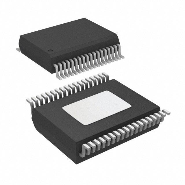


 工商网监
湘ICP备2023018690号
工商网监
湘ICP备2023018690号
