ICS9112A-16
TM
Low Skew Output Buffer
General Description
Features
The ICS9112A-16 is a high performance, low skew, low
jitter clock driver. It uses a phase lock loop (PLL)
technology to align, in both phase and frequency, the REF
input with the CLKOUT signal. It is designed to distribute
high speed clocks in PC systems operating at speeds
from 25 to
133 MHz.
•
•
•
ICS9112A-16 is a zero delay buffer that provides
synchronization between the input and output. The
synchronization is established via CLKOUT feed back to
the input of the PLL. Since the skew between the input and
output is less than +/- 350 pS, the part acts as a zero delay
buffer.
•
•
•
•
•
Zero input - output delay
Frequency range 25 - 133 MHz (3.3V)
High loop filter bandwidth ideal for Spread
Spectrum applications.
Less than 200 ps Jitter between outputs
Skew controlled outputs
Skew less than 250 ps between outputs
Available in 8 pin 150 mil SOIC
or 173 mil TSSOP package.
3.3V ±10% operation
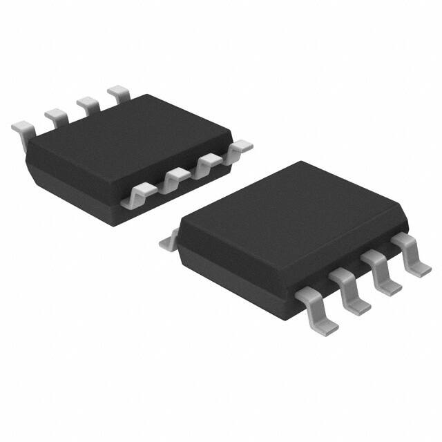
The ICS9112A-16 comes in an eight pin 150 mil SOIC or
173 mil TSSOP package. It has five output clocks. In the
absence of REF input, will be in the power down mode. In
this mode, the PLL is turned off and the output buffers are
pulled low. Power down mode provides the lowest power
consumption for a standby condition.
Block Diagram
Pin Configuration
8 pin SOIC, TSSOP
1337L—12/09/08
�ICS9112A-16
Pin Descriptions
PIN NUMBER
1
PIN NAME
2
TYPE
IN
RE F
DESCRIPTION
Input reference frequency.
2
CLK2
3
OUT
Buffered clock output
3
CLK13
OUT
Buffered clock output
4
GND
PWR
Ground
3
5
CLK3
OUT
Buffered clock output
6
VD D
PWR
Power Supply (3.3V)
OUT
Buffered clock output
OUT
Buffered clock output. Internal feedback on this pin
7
8
CLK4
3
3
CLKOUT
Notes:
1. Guaranteed by design and characterization. Not subject to 100% test.
2. Weak pull-down
3. Weak pull-down on all outputs
1337L—12/09/08
2
�ICS9112A-16
Absolute Maximum Ratings
Supply Voltage . . . . . . . . . . . . . . . . . . . . . . . 7.0 V
Logic Inputs . . . . . . . . . . . . . . . . . . . . . . . . . GND –0.5 V to VDD +0.5 V
Ambient Operating Temperature . . . . . . . . . . 0°C to +70°C
Storage Temperature . . . . . . . . . . . . . . . . . . . –65°C to +150°C
Stresses above those listed under Absolute Maximum Ratings may cause permanent damage to the device. These
ratings are stress specifications only and functional operation of the device at these or any other conditions above those
listed in the operational sections of the specifications is not implied. Exposure to absolute maximum rating conditions
for extended periods may affect product reliability.
Electrical Characteristics at 3.3V
VDD = 3.0 – 3.6 V, TA = 0 – 70° C unless otherwise stated
DC Characteristics
PARAMETER
SYMBOL
TEST CONDITIONS
MI N
TYP
MAX
UNITS
0.8
V
Input Low Voltage
VIL
Input High Voltage
VIH
Input Low Current
IIL
VIN=0V
19
50.0
µA
Input High Current
IIH
VIN=VDD
0.10
100.0
µA
0.25
0.4
V
2.0
V
Output Low Voltage1
VOL
IOL = 25mA
Output High Voltage1
VOH
IOH = 25mA
Power Down Supply
Current
IDD
REF = 0 MHz
0.3
50.0
µA
Supply Current
IDD
Unloaded oututs at 66.66 MHz
SEL inputs at VDD or GND
30.0
40.0
mA
2.4
2.9
V
Notes:
1. Guaranteed by design and characterization. Not subject to 100% test.
2. All Skew specifications are mesured with a 50Ω transmission line, load teminated with 50Ω to 1.4V.
3. Duty cycle measured at 1.4V.
4. Skew measured at 1.4V on rising edges. Loading must be equal on outputs.
1337L—12/09/08
3
�ICS9112A-16
Switching Characteristics
PARAMETER
SYMBOL
CONDITION
MIN
TYP
MAX
UNITS
Output period
t1
With CL=30pF
40.00
(25)
7.5
(133)
ns
(MHz)
Input period
t1
With CL=30pF
40.00
(25)
7.5
(133)
ns
(MHz)
Duty Cycle1
Dt1
Measured at 1.4V; CL=30pF
40.0
50
60
%
Duty Cycle1
Dt2
Measured at VDD/2 Fout
很抱歉,暂时无法提供与“9112AM-16LF”相匹配的价格&库存,您可以联系我们找货
免费人工找货