C8051F300/1/2/3/4/5
Mixed Signal ISP Flash MCU Family
Analog Peripherals - 8-Bit ADC ('F300/2 only)
• • • • • •
High Speed 8051 µc Core - Pipelined instruction architecture; executes 70% of
instructions in 1 or 2 system clocks
Up to 500 ksps Up to 8 external inputs Programmable amplifier gains of 4, 2, 1, & 0.5 VREF from external pin or VDD Built-in temperature sensor External conversion start input Programmable hysteresis and response time Configurable as interrupt or reset source Low current ( ‘1’. Switch the system clock to the external oscillator.
Note: Tuning-fork crystals may require additional settling time before XTLVLD returns a valid result. The capacitors shown in the external crystal configuration provide the load capacitance required by the crystal for correct oscillation. These capacitors are “in series” as seen by the crystal and “in parallel” with the stray capacitance of the XTAL1 and XTAL2 pins. Note: The load capacitance depends upon the crystal and the manufacturer. Please refer to the crystal data sheet when completing these calculations. For example, a tuning-fork crystal of 32.768 kHz with a recommended load capacitance of 12.5 pF should use the configuration shown in Figure 12.1, Option 1. The total value of the capacitors and the stray capacitance of the XTAL pins should equal 25 pF. With a stray capacitance of 3 pF per pin, the 22 pF capacitors yield an equivalent capacitance of 12.5 pF across the crystal, as shown in Figure 11.2.
22 pF XTAL1 32.768 kHz 10 MΩ XTAL2 22 pF
Figure 11.2. 32.768 kHz External Crystal Example
Rev. 2.8
99
�C8051F300/1/2/3/4/5
11.5. External RC Example
If an RC network is used as an external oscillator source for the MCU, the circuit should be configured as shown in Figure 11.1, Option 2. The capacitor should be no greater than 100 pF; however for very small capacitors, the total capacitance may be dominated by parasitic capacitance in the PCB layout. To determine the required External Oscillator Frequency Control value (XFCN) in the OSCXCN Register, first select the RC network value to produce the desired frequency of oscillation. If the frequency desired is 100 kHz, let R = 246 kΩ and C = 50 pF: f = 1.23( 103 ) / RC = 1.23 ( 103 ) / [ 246 x 50 ] = 0.1 MHz = 100 kHz Referring to the table in SFR Definition 11.3, the required XFCN setting is 010b.
11.6. External Capacitor Example
If a capacitor is used as an external oscillator for the MCU, the circuit should be configured as shown in Figure 11.1, Option 3. The capacitor should be no greater than 100 pF; however for very small capacitors, the total capacitance may be dominated by parasitic capacitance in the PCB layout. To determine the required External Oscillator Frequency Control value (XFCN) in the OSCXCN Register, select the capacitor to be used and find the frequency of oscillation from the equations below. Assume VDD = 3.0 V and f = 150 kHz: f = KF / (C x VDD) 0.150 MHz = KF / (C x 3.0) Since the frequency of roughly 150 kHz is desired, select the K Factor from the table in SFR Definition 11.3 as KF = 22: 0.150 MHz = 22 / (C x 3.0) C x 3.0 = 22 / 0.150 MHz C = 146.6 / 3.0 pF = 48.8 pF Therefore, the XFCN value to use in this example is 011b and C = 50 pF.
100
Rev. 2.8
�C8051F300/1/2/3/4/5
12. Port Input/Output
Digital and analog resources are available through a byte-wide digital I/O Port, Port0. Each of the Port pins can be defined as general-purpose I/O (GPIO), analog input, or assigned to one of the internal digital resources as shown in Figure 12.3. The designer has complete control over which functions are assigned, limited only by the number of physical I/O pins. This resource assignment flexibility is achieved through the use of a Priority Crossbar Decoder. Note that the state of a Port I/O pin can always be read in the corresponding Port latch, regardless of the Crossbar settings. The Crossbar assigns the selected internal digital resources to the I/O pins based on the Priority Decoder (Figure 12.3 and Figure 12.4). The registers XBR0, XBR1, and XBR2, defined in SFR Definition 12.1, SFR Definition 12.2, and SFR Definition 12.3 are used to select internal digital functions. All Port I/Os are 5 V tolerant (refer to Figure 12.2 for the Port cell circuit). The Port I/O cells are configured as either push-pull or open-drain in the Port0 Output Mode register (P0MDOUT). Complete Electrical Specifications for Port I/O are given in Table 12.1 on page 108.
XBR0, XBR1, XBR2 Registers
P0MDOUT, P0MDIN Registers
Priority Decoder
Highest Priority UART SMBus (Internal Digital Signals) CP0 Outputs SYSCLK PCA T0, T1 4 2 8 Lowest Priority Port Latch P0 (P0.0-P0.7) 2 2 2 8 P0 I/O Cells
Digital Crossbar
P0.0 P0.7
Figure 12.1. Port I/O Functional Block Diagram
/WEAK-PULLUP
PUSH-PULL /PORT-OUTENABLE
VDD
VDD
(WEAK) PORT PAD
PORT-OUTPUT
Analog Select ANALOG INPUT PORT-INPUT
GND
Figure 12.2. Port I/O Cell Block Diagram
Rev. 2.8
101
�C8051F300/1/2/3/4/5
12.1. Priority Crossbar Decoder
The Priority Crossbar Decoder (Figure 12.3) assigns a priority to each I/O function, starting at the top with UART0. When a digital resource is selected, the least significant unassigned Port pin is assigned to that resource (excluding UART0, which is always at pins 4 and 5). If a Port pin is assigned, the Crossbar skips that pin when assigning the next selected resource. Additionally, the Crossbar will skip Port pins whose associated bits in the XBR0 register are set. The XBR0 register allows software to skip Port pins that are to be used for analog input or GPIO. Important Note on Crossbar Configuration: If a Port pin is claimed by a peripheral without use of the Crossbar, its corresponding XBR0 bit should be set. This applies to P0.0 if VREF is enabled, P0.3 and/or P0.2 if the external oscillator circuit is enabled, P0.6 if the ADC is configured to use the external conversion start signal (CNVSTR), and any selected ADC or Comparator inputs. The Crossbar skips selected pins as if they were already assigned, and moves to the next unassigned pin. Figure 12.3 shows the Crossbar Decoder priority with no Port pins skipped (XBR0 = 0x00); Figure 12.4 shows the Crossbar Decoder priority with pins 6 and 2 skipped (XBR0 = 0x44).
P0 SF Signals VREF PIN I/O 0 TX0 RX0 Signals Unavailable 0 0 0 0 0 0 0 0 XBR0[0:7] Port pin potentially available to peripheral SF Signals Special Function Signals are not assigned by the crossbar. When these signals are enabled, the CrossBar must be manually configured to skip their corresponding port pins. Note: x1 refers to the XTAL1 signal; x2 refers to the XTAL2 signal. SDA SCL CP0 CP0A SYSCLK CEX0 CEX1 CEX2 ECI T0 T1 1 x1 2 x2 3 4 5 CNVSTR 6 7
Figure 12.3. Crossbar Priority Decoder with XBR0 = 0x00
102
Rev. 2.8
�C8051F300/1/2/3/4/5
P0 SF Signals VREF PIN I/O 0 TX0 Signals Unavailable 0 0 1 0 0 0 1 0 XBR0[0:7] Port pin potentially available to peripheral Port pin skipped by CrossBar SF Signals Special Function Signals are not assigned by the crossbar. When these signals are enabled, the CrossBar must be manually configured to skip their corresponding port pins. Note: x1 refers to the XTAL1 signal; x2 refers to the XTAL2 signal. RX0 SDA SCL CP0 CP0A SYSCLK CEX0 CEX1 CEX2 ECI T0 T1 1 x1 2 x2 3 4 5 CNVSTR 6 7
Figure 12.4. Crossbar Priority Decoder with XBR0 = 0x44
Registers XBR1 and XBR2 are used to assign the digital I/O resources to the physical I/O Port pins. Note that when the SMBus is selected, the Crossbar assigns both pins associated with the SMBus (SDA and SCL). Either or both of the UART signals may be selected by the Crossbar. UART0 pin assignments are fixed for bootloading purposes: when UART TX0 is selected, it is always assigned to P0.4; when UART RX0 is selected, it is always assigned to P0.5. Standard Port I/Os appear contiguously after the prioritized functions have been assigned. For example, if assigned functions that take the first 3 Port I/O (P0.[2:0]), 5 Port I/O are left for analog or GPIO use.
Rev. 2.8
103
�C8051F300/1/2/3/4/5
12.2. Port I/O Initialization
Port I/O initialization consists of the following steps: Step 1. Select the input mode (analog or digital) for all Port pins, using the Port0 Input Mode register (P0MDIN). Step 2. Select the output mode (open-drain or push-pull) for all Port pins, using the Port0 Output Mode register (P0MDOUT). Step 3. Set XBR0 to skip any pins selected as analog inputs or special functions. Step 4. Assign Port pins to desired peripherals. Step 5. Enable the Crossbar.
All Port pins must be configured as either analog or digital inputs. Any pins to be used as Comparator or ADC inputs should be configured as an analog inputs. When a pin is configured as an analog input, its weak pull-up, digital driver, and digital receiver is disabled. This process saves power and reduces noise on the analog input. Pins configured as digital inputs may still be used by analog peripherals; however this practice is not recommended. Additionally, all analog input pins should be configured to be skipped by the Crossbar (accomplished by setting the associated bits in XBR0). Port input mode is set in the P0MDIN register, where a ‘1’ indicates a digital input, and a ‘0’ indicates an analog input. All pins default to digital inputs on reset. See SFR Definition 12.5 for the P0MDIN register details. The output driver characteristics of the I/O pins are defined using the Port0 Output Mode register P0MDOUT (see SFR Definition 12.6). Each Port Output driver can be configured as either open drain or push-pull. This selection is required even for the digital resources selected in the XBRn registers, and is not automatic. The only exception to this is the SMBus (SDA, SCL) pins, which are configured as opendrain regardless of the P0MDOUT settings. When the WEAKPUD bit in XBR2 is ‘0’, a weak pull-up is enabled for all Port I/O configured as open-drain. WEAKPUD does not affect the push-pull Port I/O. Furthermore, the weak pull-up is turned off on an open-drain output that is driving a ‘0’ to avoid unnecessary power dissipation. Registers XBR0, XBR1 and XBR2 must be loaded with the appropriate values to select the digital I/O functions required by the design. Setting the XBARE bit in XBR2 to ‘1’ enables the Crossbar. Until the Crossbar is enabled, the external pins remain as standard digital inputs (output drivers disabled) regardless of the XBRn Register settings. For given XBRn Register settings, one can determine the I/O pin-out using the Priority Decode Table; as an alternative, the Configuration Wizard utility of the Silicon Labs IDE software will determine the Port I/O pin assignments based on the XBRn Register settings.
104
Rev. 2.8
�C8051F300/1/2/3/4/5
SFR Definition 12.1. XBR0: Port I/O Crossbar Register 0
R/W R/W R/W R/W R/W R/W R/W R/W Reset Value
—
Bit7
XSKP6
Bit6
XSKP5
Bit5
XSKP4
Bit4
XSKP3
Bit3
XSKP2
Bit2
XSKP1
Bit1
XSKP0
Bit0
00000000
SFR Address:
0xE1 Bit7: UNUSED. Read = 0b; Write = don’t care. Bits6–0: XSKP[6:0]: Crossbar Skip Enable Bits These bits select Port pins to be skipped by the Crossbar Decoder. Port pins used as analog inputs (for ADC or Comparator) or used as special functions (VREF input, external oscillator circuit, CNVSTR input) should be skipped by the Crossbar. 0: Corresponding P0.n pin is not skipped by the Crossbar. 1: Corresponding P0.n pin is skipped by the Crossbar.
SFR Definition 12.2. XBR1: Port I/O Crossbar Register 1
R/W Bit7 R/W Bit6 R/W Bit5 R/W Bit4 R/W Bit3 R/W Bit2 R/W Bit1 R/W Bit0 Reset Value SFR Address:
PCA0ME
CP0AOEN CP0OEN SYSCKE SMB0OEN URX0EN UTX0EN 00000000 0xE2
Bits7–6: PCA0ME: PCA Module I/0 Enable Bits 00: All PCA I/O unavailable at Port pins. 01: CEX0 routed to Port pin. 10: CEX0, CEX1 routed to Port pins. 11: CEX0, CEX1, CEX2 routed to Port pins. Bit5: CP0AOEN: Comparator0 Asynchronous Output Enable 0: Asynchronous CP0 unavailable at Port pin. 1: Asynchronous CP0 routed to Port pin. Bit4: CP0OEN: Comparator0 Output Enable 0: CP0 unavailable at Port pin. 1: CP0 routed to Port pin. Bit3: SYSCKE: /SYSCLK Output Enable 0: /SYSCLK unavailable at Port pin. 1: /SYSCLK output routed to Port pin. Bit2: SMB0OEN: SMBus I/O Enable 0: SMBus I/O unavailable at Port pins. 1: SDA, SCL routed to Port pins. Bit1: URX0EN: UART RX Enable 0: UART RX0 unavailable at Port pin. 1: UART RX0 routed to Port pin P0.5. Bit0: UTX0EN: UART TX Output Enable 0: UART TX0 unavailable at Port pin. 1: UART TX0 routed to Port pin P0.4.
Rev. 2.8
105
�C8051F300/1/2/3/4/5
SFR Definition 12.3. XBR2: Port I/O Crossbar Register 2
R/W R/W R/W R/W R/W R/W R/W R/W Reset Value
WEAKPUD
Bit7
XBARE
Bit6
—
Bit5
—
Bit4
—
Bit3
T1E
Bit2
T0E
Bit1
ECIE
Bit0
00000000
SFR Address:
0xE3 Bit7: WEAKPUD: Port I/O Weak Pull-up Disable. 0: Weak Pull-ups enabled (except for Ports whose I/O are configured as push-pull). 1: Weak Pull-ups disabled. Bit6: XBARE: Crossbar Enable. 0: Crossbar disabled. 1: Crossbar enabled. Bits5–3: UNUSED: Read = 000b. Write = don’t care. Bit2: T1E: T1 Enable. 0: T1 unavailable at Port pin. 1: T1 routed to Port pin. Bit1: T0E: T0 Enable. 0: T0 unavailable at Port pin. 1: T0 routed to Port pin. Bit0: ECIE: PCA0 Counter Input Enable. 0: ECI unavailable at Port pin. 1: ECI routed to Port pin.
12.3. General Purpose Port I/O
Port pins that remain unassigned by the Crossbar and are not used by analog peripherals can be used for general purpose I/O. Port0 is accessed through a corresponding special function register (SFR) that is both byte addressable and bit addressable. When writing to a Port, the value written to the SFR is latched to maintain the output data value at each pin. When reading, the logic levels of the Port's input pins are returned regardless of the XBRn settings (i.e., even when the pin is assigned to another signal by the Crossbar, the Port register can always read its corresponding Port I/O pin). The exception to this is the execution of the read-modify-write instructions. The read-modify-write instructions when operating on a Port SFR are the following: ANL, ORL, XRL, JBC, CPL, INC, DEC, DJNZ and MOV, CLR or SET, when the destination is an individual bit in a Port SFR. For these instructions, the value of the register (not the pin) is read, modified, and written back to the SFR.
106
Rev. 2.8
�C8051F300/1/2/3/4/5
SFR Definition 12.4. P0: Port0 Register
R/W R/W R/W R/W R/W R/W R/W R/W Reset Value
P0.7
Bit7
P0.6
Bit6
P0.5
Bit5
P0.4
Bit4
P0.3
Bit3
P0.2
Bit2
P0.1
Bit1
P0.0
Bit0 (bit addressable)
11111111
SFR Address:
0x80
Bits7–0: P0.[7:0] Write - Output appears on I/O pins per XBR0, XBR1, and XBR2 Registers 0: Logic Low Output. 1: Logic High Output (open-drain if corresponding P0MDOUT.n bit = 0) Read - Always reads ‘1’ if selected as analog input in register P0MDIN. Directly reads Port pin when configured as digital input. 0: P0.n pin is logic low. 1: P0.n pin is logic high.
SFR Definition 12.5. P0MDIN: Port0 Input Mode
R/W Bit7 R/W Bit6 R/W Bit5 R/W Bit4 R/W Bit3 R/W Bit2 R/W Bit1 R/W Bit0 Reset Value
11111111
SFR Address:
0xF1 Bits7–0: Input Configuration Bits for P0.7-P0.0 (respectively) Port pins configured as analog inputs have their weak pull-up, digital driver, and digital receiver disabled. 0: Corresponding P0.n pin is configured as an analog input. 1: Corresponding P0.n pin is configured as a digital input.
Rev. 2.8
107
�C8051F300/1/2/3/4/5
SFR Definition 12.6. P0MDOUT: Port0 Output Mode
R/W Bit7 R/W Bit6 R/W Bit5 R/W Bit4 R/W Bit3 R/W Bit2 R/W Bit1 R/W Bit0 Reset Value
00000000
SFR Address:
0xA4 Bits7–0: Output Configuration Bits for P0.7–P0.0 (respectively): ignored if corresponding bit in register P0MDIN is logic 0. 0: Corresponding P0.n Output is open-drain. 1: Corresponding P0.n Output is push-pull. (Note: When SDA and SCL appear on any of the Port I/O, each are open-drain regardless of the value of P0MDOUT).
Table 12.1. Port I/O DC Electrical Characteristics
VDD = 2.7 to 3.6 V, –40 to +85 °C unless otherwise specified.
Parameters Output High Voltage
Output Low Voltage
Conditions IOH = –3 mA, Port I/O push-pull IOH = –10 µA, Port I/O push-pull IOH = –10 mA, Port I/O push-pull IOL = 8.5 mA IOL = 10 µA IOL = 25 mA
Min VDD – 0.7 VDD – 0.1 — — — 2.0 — —
Typ
Max —
Units V
VDD-0.8 — — 1.0 — — 25 0.6 0.1 — — 0.8 ±1 40 V V V µA
Input High Voltage Input Low Voltage Input Leakage Current
Weak Pull-up Off Weak Pull-up On, VIN = 0 V
108
Rev. 2.8
�C8051F300/1/2/3/4/5
13. SMBus
The SMBus I/O interface is a two-wire bidirectional serial bus. The SMBus is compliant with the System Management Bus Specification, version 1.1, and compatible with the I2C serial bus. Reads and writes to the interface by the system controller are byte oriented with the SMBus interface autonomously controlling the serial transfer of the data. Data can be transferred at up to 1/10th of the system clock operating as master or slave (this can be faster than allowed by the SMBus specification, depending on the system clock used). A method of extending the clock-low duration is available to accommodate devices with different speed capabilities on the same bus. The SMBus interface may operate as a master and/or slave, and may function on a bus with multiple masters. The SMBus provides control of SDA (serial data), SCL (serial clock) generation and synchronization, arbitration logic, and START/STOP control and generation. Three SFRs are associated with the SMBus: SMB0CF configures the SMBus; SMB0CN controls the status of the SMBus; and SMB0DAT is the data register, used for both transmitting and receiving SMBus data and slave addresses.
SMB0CN MT SSAAAS AXTTCRC I SMAOKBK TO RL ED QO RE S T
SMB0CF E I BESSSS N N U XMMMM SHSTBBBB M YHTFCC B OOT S S LEE10 D
00 01 10 11 SMBUS CONTROL LOGIC Arbitration SCL Synchronization SCL Generation (Master Mode) SDA Control Data Path IRQ Generation Control
T0 Overflow T1 Overflow TMR2H Overflow TMR2L Overflow SCL
FILTER
Interrupt Request
SCL Control SDA Control
N
C R O S S B A R SDA
Port I/O
SMB0DAT 76543210
FILTER
N
Figure 13.1. SMBus Block Diagram
Rev. 2.8
109
�C8051F300/1/2/3/4/5
13.1. Supporting Documents
It is assumed the reader is familiar with or has access to the following supporting documents: 1. The I2C-Bus and How to Use It (including specifications), Philips Semiconductor. 2. The I2C-Bus Specification – Version 2.0, Philips Semiconductor. 3. System Management Bus Specification – Version 1.1, SBS Implementers Forum.
13.2. SMBus Configuration
Figure 13.2 shows a typical SMBus configuration. The SMBus specification allows any recessive voltage between 3.0 and 5.0 V; different devices on the bus may operate at different voltage levels. The bidirectional SCL (serial clock) and SDA (serial data) lines must be connected to a positive power supply voltage through a pull-up resistor or similar circuit. Every device connected to the bus must have an open-drain or open-collector output for both the SCL and SDA lines, so that both are pulled high (recessive state) when the bus is free. The maximum number of devices on the bus is limited only by the requirement that the rise and fall times on the bus not exceed 300 ns and 1000 ns, respectively.
VDD = 5V
VDD = 3V
VDD = 5V
VDD = 3V
Master Device
Slave Device 1
Slave Device 2
SDA SCL
Figure 13.2. Typical SMBus Configuration 13.3. SMBus Operation
Two types of data transfers are possible: data transfers from a master transmitter to an addressed slave receiver (WRITE), and data transfers from an addressed slave transmitter to a master receiver (READ). The master device initiates both types of data transfers and provides the serial clock pulses on SCL. The SMBus interface may operate as a master or a slave, and multiple master devices on the same bus are supported. If two or more masters attempt to initiate a data transfer simultaneously, an arbitration scheme is employed with a single master always winning the arbitration. Note that it is not necessary to specify one device as the Master in a system; any device that transmits a START and a slave address becomes the master for the duration of that transfer. A typical SMBus transaction consists of a START condition followed by an address byte (Bits7–1: 7-bit slave address; Bit0: R/W direction bit), one or more bytes of data, and a STOP condition. Each byte that is received (by a master or slave) must be acknowledged (ACK) with a low SDA during a high SCL (see Figure 13.3). If the receiving device does not ACK, the transmitting device will read a NACK (not acknowledge), which is a high SDA during a high SCL.
110
Rev. 2.8
�C8051F300/1/2/3/4/5
The direction bit (R/W) occupies the least significant bit position of the address byte. The direction bit is set to logic 1 to indicate a "READ" operation and cleared to logic 0 to indicate a "WRITE" operation. All transactions are initiated by a master, with one or more addressed slave devices as the target. The master generates the START condition and then transmits the slave address and direction bit. If the transaction is a WRITE operation from the master to the slave, the master transmits the data a byte at a time waiting for an ACK from the slave at the end of each byte. For READ operations, the slave transmits the data waiting for an ACK from the master at the end of each byte. At the end of the data transfer, the master generates a STOP condition to terminate the transaction and free the bus. Figure 13.3 illustrates a typical SMBus transaction.
SCL
SDA SLA6 SLA5-0 R/W D7 D6-0
START
Slave Address + R/W
ACK
Data Byte
NACK
STOP
Figure 13.3. SMBus Transaction
13.3.1. Arbitration
A master may start a transfer only if the bus is free. The bus is free after a STOP condition or after the SCL and SDA lines remain high for a specified time (see Section “13.3.4. SCL High (SMBus Free) Timeout” on page 112). In the event that two or more devices attempt to begin a transfer at the same time, an arbitration scheme is employed to force one master to give up the bus. The master devices continue transmitting until one attempts a HIGH while the other transmits a LOW. Since the bus is open-drain, the bus will be pulled LOW. The master attempting the HIGH will detect a LOW SDA and lose the arbitration. The winning master continues its transmission without interruption; the losing master becomes a slave and receives the rest of the transfer if addressed. This arbitration scheme is non-destructive: one device always wins, and no data is lost.
Rev. 2.8
111
�C8051F300/1/2/3/4/5
13.3.2. Clock Low Extension
SMBus provides a clock synchronization mechanism, similar to I2C, which allows devices with different speed capabilities to coexist on the bus. A clock-low extension is used during a transfer in order to allow slower slave devices to communicate with faster masters. The slave may temporarily hold the SCL line LOW to extend the clock low period, effectively decreasing the serial clock frequency.
13.3.3. SCL Low Timeout
If the SCL line is held low by a slave device on the bus, no further communication is possible. Furthermore, the master cannot force the SCL line high to correct the error condition. To solve this problem, the SMBus protocol specifies that devices participating in a transfer must detect any clock cycle held low longer than 25 ms as a “timeout” condition. Devices that have detected the timeout condition must reset the communication no later than 10 ms after detecting the timeout condition. When the SMBTOE bit in SMB0CF is set, Timer 2 is used to detect SCL low timeouts. Timer 2 is forced to reload when SCL is high, and allowed to count when SCL is low. With Timer 2 enabled and configured to overflow after 25 ms (and SMBTOE set), the Timer 2 interrupt service routine can be used to reset (disable and reenable) the SMBus in the event of an SCL low timeout. Timer 2 configuration details can be found in Section “15.2. Timer 2” on page 149.
13.3.4. SCL High (SMBus Free) Timeout
The SMBus specification stipulates that if the SCL and SDA lines remain high for more that 50 µs, the bus is designated as free. When the SMBFTE bit in SMB0CF is set, the bus will be considered free if SCL and SDA remain high for more than 10 SMBus clock source periods. If the SMBus is waiting to generate a Master START, the START will be generated following this timeout. Note that a clock source is required for free timeout detection, even in a slave-only implementation.
112
Rev. 2.8
�C8051F300/1/2/3/4/5
13.4. Using the SMBus
The SMBus can operate in both Master and Slave modes. The interface provides timing and shifting control for serial transfers; higher level protocol is determined by user software. The SMBus interface provides the following application-independent features: • • • • • • • Byte-wise serial data transfers Clock signal generation on SCL (Master Mode only) and SDA data synchronization Timeout/bus error recognition, as defined by the SMB0CF configuration register START/STOP timing, detection, and generation Bus arbitration Interrupt generation Status information
SMBus interrupts are generated for each data byte or slave address that is transferred. When transmitting, this interrupt is generated after the ACK cycle so that software may read the received ACK value; when receiving data, this interrupt is generated before the ACK cycle so that software may define the outgoing ACK value. See Section “13.5. SMBus Transfer Modes” on page 121 for more details on transmission sequences. Interrupts are also generated to indicate the beginning of a transfer when a master (START generated), or the end of a transfer when a slave (STOP detected). Software should read the SMB0CN (SMBus Control register) to find the cause of the SMBus interrupt. The SMB0CN register is described in Section “13.4.2. SMB0CN Control Register” on page 117; Table 13.4 provides a quick SMB0CN decoding reference. SMBus configuration options include: • • • • Timeout detection (SCL Low Timeout and/or Bus Free Timeout) SDA setup and hold time extensions Slave event enable/disable Clock source selection
These options are selected in the SMB0CF register, as described in Section “13.4.1. SMBus Configuration Register” on page 114.
Rev. 2.8
113
�C8051F300/1/2/3/4/5
13.4.1. SMBus Configuration Register
The SMBus Configuration register (SMB0CF) is used to enable the SMBus Master and/or Slave modes, select the SMBus clock source, and select the SMBus timing and timeout options. When the ENSMB bit is set, the SMBus is enabled for all master and slave events. Slave events may be disabled by setting the INH bit. With slave events inhibited, the SMBus interface will still monitor the SCL and SDA pins; however, the interface will NACK all received addresses and will not generate any slave interrupts. When the INH bit is set, all slave events will be inhibited following the next START (interrupts will continue for the duration of the current transfer).
Table 13.1. SMBus Clock Source Selection
SMBCS1 0 0 1 1 SMBCS0 0 1 0 1 SMBus Clock Source Timer 0 Overflow Timer 1 Overflow Timer 2 High Byte Overflow Timer 2 Low Byte Overflow
The SMBCS1-0 bits select the SMBus clock source, which is used only when operating as a master or when the Free Timeout detection is enabled. When operating as a master, overflows from the selected source determine the absolute minimum SCL low and high times as defined in Equation 13.1. Note that the selected clock source may be shared by other peripherals so long as the timer is left running at all times. For example, Timer 1 overflows may generate the SMBus and UART baud rates simultaneously. Timer configuration is covered in Section “15. Timers” on page 141.
1 T HighMin = T LowMin = --------------------------------------------f ClockSourceOverflow Equation 13.1. Minimum SCL High and Low Times
The selected clock source should be configured to establish the minimum SCL High and Low times as per Equation 13.1. When the interface is operating as a master (and SCL is not driven or extended by any other devices on the bus), the typical SMBus bit rate is approximated by Equation 13.2.
f ClockSourceOverflow BitRate = --------------------------------------------3 Equation 13.2. Typical SMBus Bit Rate
Figure 13.4 shows the typical SCL generation described by Equation 13.2. Notice that THIGH is typically twice as large as TLOW. The actual SCL output may vary due to other devices on the bus (SCL may be extended low by slower slave devices, or driven low by contending master devices). The bit rate when operating as a master will never exceed the limits defined by equation Equation 13.1.
114
Rev. 2.8
�C8051F300/1/2/3/4/5
Timer Source Overflows SCL
TLow
THigh
SCL High Timeout
Figure 13.4. Typical SMBus SCL Generation
Setting the EXTHOLD bit extends the minimum setup and hold times for the SDA line. The minimum SDA setup time defines the absolute minimum time that SDA is stable before SCL transitions from low-to-high. The minimum SDA hold time defines the absolute minimum time that the current SDA value remains stable after SCL transitions from high-to-low. EXTHOLD should be set so that the minimum setup and hold times meet the SMBus Specification requirements of 250 ns and 300 ns, respectively. Table 13.2 shows the minimum setup and hold times for the two EXTHOLD settings. Setup and hold time extensions are typically necessary when SYSCLK is above 10 MHz.
Table 13.2. Minimum SDA Setup and Hold Times
EXTHOLD 0 Minimum SDA Setup Time Tlow – 4 system clocks OR 1 system clock + s/w delay* 11 system clocks Minimum SDA Hold Time 3 system clocks
1
12 system clocks
*Note: Setup Time for ACK bit transmissions and the MSB of all data transfers. The s/w delay occurs between the time SMB0DAT or ACK is written and when SI is cleared. Note that if SI is cleared in the same write that defines the outgoing ACK value, s/w delay is zero.
With the SMBTOE bit set, Timer 2 should be configured to overflow after 25 ms in order to detect SCL low timeouts (see Section “13.3.3. SCL Low Timeout” on page 112). The SMBus interface will force Timer 2 to reload while SCL is high, and allow Timer 2 to count when SCL is low. The Timer 2 interrupt service routine should be used to reset SMBus communication by disabling and reenabling the SMBus. Timer 2 configuration is described in Section “15.2. Timer 2” on page 149. SMBus Free Timeout detection can be enabled by setting the SMBFTE bit. When this bit is set, the bus will be considered free if SDA and SCL remain high for more than 10 SMBus clock source periods (see Figure 13.4). When a Free Timeout is detected, the interface will respond as if a STOP was detected (an interrupt will be generated, and STO will be set).
Rev. 2.8
115
�C8051F300/1/2/3/4/5
SFR Definition 13.1. SMB0CF: SMBus Clock/Configuration
R/W R/W R R/W Bit4 R/W Bit3 R/W Bit2 R/W Bit1 R/W Bit0 Reset Value SFR Address:
ENSMB
Bit7
INH
Bit6
BUSY
Bit5
EXTHOLD SMBTOE SMBFTE SMBCS1 SMBCS0 00000000 0xC1
Bit7:
ENSMB: SMBus Enable. This bit enables/disables the SMBus interface. When enabled, the interface constantly monitors the SDA and SCL pins. 0: SMBus interface disabled. 1: SMBus interface enabled. Bit6: INH: SMBus Slave Inhibit. When this bit is set to logic 1, the SMBus does not generate an interrupt when slave events occur. This effectively removes the SMBus slave from the bus. Master Mode interrupts are not affected. 0: SMBus Slave Mode enabled. 1: SMBus Slave Mode inhibited. Bit5: BUSY: SMBus Busy Indicator. This bit is set to logic 1 by hardware when a transfer is in progress. It is cleared to logic 0 when a STOP or free timeout is sensed. Bit4: EXTHOLD: SMBus Setup and Hold Time Extension Enable. This bit controls the SDA setup and hold times according to Table 13.2. 0: SDA Extended Setup and Hold Times disabled. 1: SDA Extended Setup and Hold Times enabled. Bit3: SMBTOE: SMBus SCL Timeout Detection Enable. This bit enables SCL low timeout detection. If set to logic 1, the SMBus forces Timer 2 to reload while SCL is high and allows Timer 2 to count when SCL goes low. If Timer 2 is configured in split mode (T2SPLIT is set), only the high byte of Timer 2 is held in reload while SCL is high. Timer 2 should be programmed to generate interrupts at 25 ms, and the Timer 2 interrupt service routine should reset SMBus communication. Bit2: SMBFTE: SMBus Free Timeout Detection Enable. When this bit is set to logic 1, the bus will be considered free if SCL and SDA remain high for more than 10 SMBus clock source periods. Bits1–0: SMBCS1-SMBCS0: SMBus Clock Source Selection. These two bits select the SMBus clock source, which is used to generate the SMBus bit rate. The selected device should be configured according to Equation 13.1. SMBCS1 0 0 1 1 SMBCS0 0 1 0 1 SMBus Clock Source Timer 0 Overflow Timer 1 Overflow Timer 2 High Byte Overflow Timer 2 Low Byte Overflow
116
Rev. 2.8
�C8051F300/1/2/3/4/5
13.4.2. SMB0CN Control Register
SMB0CN is used to control the interface and to provide status information (see SFR Definition 13.2). The higher four bits of SMB0CN (MASTER, TXMODE, STA, and STO) form a status vector that can be used to jump to service routines. MASTER and TXMODE indicate the master/slave state and transmit/receive modes, respectively. The STA bit indicates that a START has been detected or generated since the last SMBus interrupt. When set to ‘1’, the STA bit will cause the SMBus to enter Master mode and generate a START when the bus becomes free. STA is not cleared by hardware after the START is generated; it must be cleared by software. As a master, writing the STO bit will cause the hardware to generate a STOP condition and end the current transfer after the next ACK cycle. STO is cleared by hardware after the STOP condition is generated. As a slave, STO indicates that a STOP condition has been detected since the last SMBus interrupt. STO is also used in slave mode to manage the transition from slave receiver to slave transmitter; see Section 13.5.4 for details on this procedure. If STO and STA are both set to ‘1’ (while in Master Mode), a STOP followed by a START will be generated. As a receiver, writing the ACK bit defines the outgoing ACK value; as a transmitter, reading the ACK bit indicates the value received on the last ACK cycle. ACKRQ is set each time a byte is received, indicating that an outgoing ACK value is needed. When ACKRQ is set, software should write the desired outgoing value to the ACK bit before clearing SI. A NACK will be generated if software does not write the ACK bit before clearing SI. SDA will reflect the defined ACK value immediately following a write to the ACK bit; however SCL will remain low until SI is cleared. If a received slave address is not acknowledged, further slave events will be ignored until the next START is detected. The ARBLOST bit indicates that the interface has lost an arbitration. This may occur anytime the interface is transmitting (master or slave). A lost arbitration while operating as a slave indicates a bus error condition. ARBLOST is cleared by hardware each time SI is cleared. The SI bit (SMBus Interrupt Flag) is set at the beginning and end of each transfer, after each byte frame, or when an arbitration is lost; see Table 13.3 for more details. Important Note About the SI Bit: The SMBus interface is stalled while SI is set; thus SCL is held low, and the bus is stalled until software clears SI. Table 13.3 lists all sources for hardware changes to the SMB0CN bits. Refer to Table 13.4 for SMBus status decoding using the SMB0CN register.
Rev. 2.8
117
�C8051F300/1/2/3/4/5
SFR Definition 13.2. SMB0CN: SMBus Control
R Bit7 R Bit6 R/W R/W R Bit3 R Bit2 R/W R/W Reset Value
MASTER TXMODE
STA
Bit5
STO
Bit4
ACKRQ ARBLOST
ACK
Bit1
SI
Bit0 (bit addressable)
00000000
SFR Address:
0xC0
Bit7:
Bit6:
Bit5:
Bit4:
Bit3:
Bit2:
Bit1:
Bit0:
MASTER: SMBus Master/Slave Indicator. This read-only bit indicates when the SMBus is operating as a master. 0: SMBus operating in Slave Mode. 1: SMBus operating in Master Mode. TXMODE: SMBus Transmit Mode Indicator. This read-only bit indicates when the SMBus is operating as a transmitter. 0: SMBus in Receiver Mode. 1: SMBus in Transmitter Mode. STA: SMBus Start Flag. Write: 0: No Start generated. 1: When operating as a master, a START condition is transmitted if the bus is free (If the bus is not free, the START is transmitted after a STOP is received or a free timeout is detected). If STA is set by software as an active Master, a repeated START will be generated after the next ACK cycle. Read: 0: No Start or repeated Start detected. 1: Start or repeated Start detected. STO: SMBus Stop Flag. Write: As a master, setting this bit to ‘1’ causes a STOP condition to be transmitted after the next ACK cycle. STO is cleared to ‘0’ by hardware when the STOP is generated. As a slave, software manages this bit when switching from Slave Receiver to Slave Transmitter mode. See Section 13.5.4 for details. Read: 0: No Stop condition detected. 1: Stop condition detected (if in Slave Mode) or pending (if in Master Mode). ACKRQ: SMBus Acknowledge Request. This read-only bit is set to logic 1 when the SMBus has received a byte and needs the ACK bit to be written with the correct ACK response value. ARBLOST: SMBus Arbitration Lost Indicator. This read-only bit is set to logic 1 when the SMBus loses arbitration while operating as a transmitter. A lost arbitration while a slave indicates a bus error condition. ACK: SMBus Acknowledge Flag. This bit defines the outgoing ACK level and records incoming ACK levels. It should be written each time a byte is received (when ACKRQ=1), or read after each byte is transmitted. 0: A "not acknowledge" has been received (if in Transmitter Mode) OR will be transmitted (if in Receiver Mode). 1: An "acknowledge" has been received (if in Transmitter Mode) OR will be transmitted (if in Receiver Mode). SI: SMBus Interrupt Flag. This bit is set by hardware under the conditions listed in Table 13.3. SI must be cleared by software. While SI is set, SCL is held low and the SMBus is stalled.
118
Rev. 2.8
�C8051F300/1/2/3/4/5
Table 13.3. Sources for Hardware Changes to SMB0CN
Bit MASTER TXMODE Set by Hardware When: • A START is generated. Cleared by Hardware When: • A STOP is generated. • Arbitration is lost. • START is generated. • A START is detected. • The SMBus interface enters transmitter mode • Arbitration is lost. (after SMB0DAT is written before the start of • SMB0DAT is not written before the an SMBus frame). start of an SMBus frame. • A START followed by an address byte is • Must be cleared by software. received. • A STOP is detected while addressed as a • A pending STOP is generated. slave. • Arbitration is lost due to a detected STOP. • A byte has been received and an ACK • After each ACK cycle. response value is needed. • A repeated START is detected as a MASTER • Each time SI is cleared. when STA is low (unwanted repeated START). • SCL is sensed low while attempting to generate a STOP or repeated START condition. • SDA is sensed low while transmitting a ‘1’ (excluding ACK bits). • The incoming ACK value is low (ACKNOWL- • The incoming ACK value is high (NOT ACKNOWLEDGE). EDGE). • A START has been generated. • Must be cleared by software. • Lost arbitration. • A byte has been transmitted and an ACK/NACK received. • A byte has been received. • A START or repeated START followed by a slave address + R/W has been received. • A STOP has been received.
STA STO
ACKRQ ARBLOST
ACK SI
Rev. 2.8
119
�C8051F300/1/2/3/4/5
13.4.3. Data Register
The SMBus Data register SMB0DAT holds a byte of serial data to be transmitted or one that has just been received. Software may safely read or write to the data register when the SI flag is set. Software should not attempt to access the SMB0DAT register when the SMBus is enabled and the SI flag is cleared to logic 0, as the interface may be in the process of shifting a byte of data into or out of the register. Data in SMB0DAT is always shifted out MSB first. After a byte has been received, the first bit of received data is located at the MSB of SMB0DAT. While data is being shifted out, data on the bus is simultaneously being shifted in. SMB0DAT always contains the last data byte present on the bus. In the event of lost arbitration, the transition from master transmitter to slave receiver is made with the correct data or address in SMB0DAT.
SFR Definition 13.3. SMB0DAT: SMBus Data
R/W Bit7 R/W Bit6 R/W Bit5 R/W Bit4 R/W Bit3 R/W Bit2 R/W Bit1 R/W Bit0 Reset Value
00000000
SFR Address:
0xC2 Bits7–0: SMB0DAT: SMBus Data. The SMB0DAT register contains a byte of data to be transmitted on the SMBus serial interface or a byte that has just been received on the SMBus serial interface. The CPU can read from or write to this register whenever the SI serial interrupt flag (SMB0CN.0) is set to logic one. The serial data in the register remains stable as long as the SI flag is set. When the SI flag is not set, the system may be in the process of shifting data in/out and the CPU should not attempt to access this register.
120
Rev. 2.8
�C8051F300/1/2/3/4/5
13.5. SMBus Transfer Modes
The SMBus interface may be configured to operate as master and/or slave. At any particular time, it will be operating in one of the following four modes: Master Transmitter, Master Receiver, Slave Transmitter, or Slave Receiver. The SMBus interface enters Master Mode any time a START is generated, and remains in Master Mode until it loses arbitration or generates a STOP. An SMBus interrupt is generated at the end of all SMBus byte frames; however, note that the interrupt is generated before the ACK cycle when operating as a receiver, and after the ACK cycle when operating as a transmitter.
13.5.1. Master Transmitter Mode
Serial data is transmitted on SDA while the serial clock is output on SCL. The SMBus interface generates the START condition and transmits the first byte containing the address of the target slave and the data direction bit. In this case the data direction bit (R/W) will be logic 0 (WRITE). The master then transmits one or more bytes of serial data. After each byte is transmitted, an acknowledge bit is generated by the slave. The transfer is ended when the STO bit is set and a STOP is generated. Note that the interface will switch to Master Receiver Mode if SMB0DAT is not written following a Master Transmitter interrupt. Figure 13.5 shows a typical Master Transmitter sequence. Two transmit data bytes are shown, though any number of bytes may be transmitted. Notice that the ‘data byte transferred’ interrupts occur after the ACK cycle in this mode.
S
SLA
W
A
Data Byte
A
Data Byte
A
P
Interrupt
Interrupt
Interrupt
Interrupt
Received by SMBus Interface Transmitted by SMBus Interface
S = START P = STOP A = ACK W = WRITE SLA = Slave Address
Figure 13.5. Typical Master Transmitter Sequence
Rev. 2.8
121
�C8051F300/1/2/3/4/5
13.5.2. Master Receiver Mode
Serial data is received on SDA while the serial clock is output on SCL. The SMBus interface generates the START condition and transmits the first byte containing the address of the target slave and the data direction bit. In this case the data direction bit (R/W) will be logic 1 (READ). Serial data is then received from the slave on SDA while the SMBus outputs the serial clock. The slave transmits one or more bytes of serial data. After each byte is received, ACKRQ is set to ‘1’ and an interrupt is generated. Software must write the ACK bit (SMB0CN.1) to define the outgoing acknowledge value (Note: writing a ‘1’ to the ACK bit generates an ACK; writing a ‘0’ generates a NACK). Software should write a ‘0’ to the ACK bit after the last byte is received, to transmit a NACK. The interface exits Master Receiver Mode after the STO bit is set and a STOP is generated. Note that the interface will switch to Master Transmitter Mode if SMB0DAT is written while an active Master Receiver. Figure 13.6 shows a typical Master Receiver sequence. Two received data bytes are shown, though any number of bytes may be received. Notice that the ‘data byte transferred’ interrupts occur before the ACK cycle in this mode.
S
SLA
R
A
Data Byte
A
Data Byte
N
P
Interrupt
Interrupt
Interrupt
Interrupt S = START P = STOP A = ACK N = NACK R = READ SLA = Slave Address
Received by SMBus Interface Transmitted by SMBus Interface
Figure 13.6. Typical Master Receiver Sequence
122
Rev. 2.8
�C8051F300/1/2/3/4/5
13.5.3. Slave Receiver Mode
Serial data is received on SDA and the clock is received on SCL. When slave events are enabled (INH = 0), the interface enters Slave Receiver Mode when a START followed by a slave address and direction bit (WRITE in this case) is received. Upon entering Slave Receiver Mode, an interrupt is generated and the ACKRQ bit is set. Software responds to the received slave address with an ACK, or ignores the received slave address with a NACK. If the received slave address is ignored, slave interrupts will be inhibited until the next START is detected. If the received slave address is acknowledged, zero or more data bytes are received. Software must write the ACK bit after each received byte to ACK or NACK the received byte. The interface exits Slave Receiver Mode after receiving a STOP. Note that the interface will switch to Slave Transmitter Mode if SMB0DAT is written while an active Slave Receiver; see Section 13.5.4 for details on this procedure. Figure 13.7 shows a typical Slave Receiver sequence. Two received data bytes are shown, though any number of bytes may be received. Notice that the ‘data byte transferred’ interrupts occur before the ACK cycle in this mode.
Interrupt
S
SLA
W
A
Data Byte
A
Data Byte
A
P
Interrupt Received by SMBus Interface Transmitted by SMBus Interface
Interrupt
Interrupt S = START P = STOP A = ACK R = READ SLA = Slave Address
Figure 13.7. Typical Slave Receiver Sequence
Rev. 2.8
123
�C8051F300/1/2/3/4/5
13.5.4. Slave Transmitter Mode
Serial data is transmitted on SDA and the clock is received on SCL. When slave events are enabled (INH = 0), the interface enters Slave Receiver Mode (to receive the slave address) when a START followed by a slave address and direction bit (READ in this case) is received. Software responds to the received slave address with an ACK, or ignores the received slave address with a NACK. If the received address is ignored, slave interrupts will be inhibited until the next START is detected. If the received slave address is acknowledged, software should write data to SMB0DAT to force the SMBus into Slave Transmitter Mode. The switch from Slave Receiver to Slave Transmitter requires software management. Software should perform the steps outlined below only when a valid slave address is received (indicated by the label “RX-to-TX Steps” in Figure 13.8). Step 1. Step 2. Step 3. Step 4. Step 5. Step 6. Step 7. Set ACK to ‘1’. Write outgoing data to SMB0DAT. Check SMB0DAT.7; if ‘1’, do not perform steps 4, 6 or 7. Set STO to ‘1’. Clear SI to ‘0’. Poll for TXMODE => ‘1’. Clear STO to ‘0’ (must be done before the next ACK cycle).
The interface enters Slave Transmitter Mode and transmits one or more bytes of data (the above steps are only required before the first byte of the transfer). After each byte is transmitted, the master sends an acknowledge bit; if the acknowledge bit is an ACK, SMB0DAT should be written with the next data byte. If the acknowledge bit is a NACK, SMB0DAT should not be written to before SI is cleared (Note: an error condition may be generated if SMB0DAT is written following a received NACK while in Slave Transmitter Mode). The interface exits Slave Transmitter Mode after receiving a STOP. Note that the interface will switch to Slave Receiver Mode if SMB0DAT is not written following a Slave Transmitter interrupt. Figure 13.8 shows a typical Slave Transmitter sequence. Two transmitted data bytes are shown, though any number of bytes may be transmitted. Notice that the ‘data byte transferred’ interrupts occur after the ACK cycle in this mode.
Perform RX-to-TX Steps Here
Interrupt
S
SLA
R
A
Data Byte
A
Data Byte
N
P
Interrupt Received by SMBus Interface Transmitted by SMBus Interface
Interrupt
Interrupt
S = START P = STOP N = NACK W = WRITE SLA = Slave Address
Figure 13.8. Typical Slave Transmitter Sequence
124
Rev. 2.8
�C8051F300/1/2/3/4/5
13.6. SMBus Status Decoding
The current SMBus status can be easily decoded using the SMB0CN register. In the table below, STATUS VECTOR refers to the four upper bits of SMB0CN: MASTER, TXMODE, STA, and STO. Note that the shown response options are only the typical responses; application-specific procedures are allowed as long as they conform with the SMBus specification. Highlighted responses are allowed but do not conform to the SMBus specification.
Table 13.4. SMBus Status Decoding
Values Read Mode ARBLOST ACKRQ Current SMbus State Typical Response Options Values Written ACK X X X X X X X X
125
Status Vector
ACK
1110 1100 Master Transmitter
0 0 0
0 0 0
X A master START was generated. Load slave address + R/W into SMB0DAT. 0 A master data or address byte Set STA to restart transfer. was transmitted; NACK received. Abort transfer. 1 A master data or address byte Load next data byte into was transmitted; ACK received. SMB0DAT End transfer with STOP End transfer with STOP and start another transfer. Send repeated START Switch to Master Receiver Mode (clear SI without writing new data to SMB0DAT).
0 1 0 0 0 1 1 0
Rev. 2.8
STO 0 0 1 0 1 1 0 0
STA
�C8051F300/1/2/3/4/5
Table 13.4. SMBus Status Decoding (Continued)
Values Read Mode ARBLOST ACKRQ Current SMbus State Typical Response Options Values Written ACK 1 0 0 1 0 1 0 X X X X STO 0 1 1 0 0 0 0 0 0 0 0 STA 0 0 1 1 1 0 0 0 0 0 0
Rev. 2.8
Status Vector
1000
1
0
SLAVE TRANSMITTER
MASTER RECEIVER
0100
0 0 0
0 0 1 X
0101
0
126
ACK X A master data byte was received; Acknowledge received byte; ACK requested. Read SMB0DAT. Send NACK to indicate last byte, and send STOP. Send NACK to indicate last byte, and send STOP followed by START. Send ACK followed by repeated START. Send NACK to indicate last byte, and send repeated START. Send ACK and switch to Master Transmitter Mode (write to SMB0DAT before clearing SI). Send NACK and switch to Master Transmitter Mode (write to SMB0DAT before clearing SI). 0 A slave byte was transmitted; No action required (expectNACK received. ing STOP condition). 1 A slave byte was transmitted; Load SMB0DAT with next ACK received. data byte to transmit. X A Slave byte was transmitted; No action required (expecterror detected. ing Master to end transfer). X A STOP was detected while an No action required (transfer addressed Slave Transmitter. complete).
�C8051F300/1/2/3/4/5
Table 13.4. SMBus Status Decoding (Continued)
Values Read Mode ARBLOST ACKRQ Current SMbus State Typical Response Options Values Written ACK
127
Status Vector
ACK
0010
1
0
X A slave address was received; ACK requested.
1
1
X Lost arbitration as master; slave address received; ACK requested.
0010 0001
0 1 0 0
1 1 0 1 0
X Lost arbitration while attempting a repeated START. X Lost arbitration while attempting a STOP. X A STOP was detected while an addressed slave receiver. X Lost arbitration due to a detected STOP. X A slave byte was received; ACK requested.
0000
1
1
1
X
Lost arbitration while transmitting a data byte as master.
Acknowledge received 0 0 1 address (received slave address match, R/W bit = READ). Do not acknowledge 0 0 0 received address. Acknowledge received 0 0 1 address, and switch to transmitter mode (received slave address match, R/W bit = WRITE); see Section 13.5.4 for procedure. Acknowledge received 0 0 1 address (received slave address match, R/W bit = READ). Do not acknowledge 0 0 0 received address. Acknowledge received 0 0 1 address, and switch to transmitter mode (received slave address match, R/W bit = WRITE); see Section 13.5.4 for procedure. Reschedule failed transfer; 1 0 0 do not acknowledge received address Abort failed transfer. 0 0X Reschedule failed transfer. 1 0X No action required (transfer 0 0 0 complete/aborted). No action required (transfer 0 0X complete). Abort transfer. 0 0X Reschedule failed transfer. 1 0X Acknowledge received byte; 0 0 1 Read SMB0DAT. Do not acknowledge 0 0 0 received byte. Abort failed transfer. 0 0 0 Reschedule failed transfer. 1 0 0
SLAVE RECEIVER
Rev. 2.8
STO
STA
�C8051F300/1/2/3/4/5
NOTES:
128
Rev. 2.8
�C8051F300/1/2/3/4/5
14. UART0
UART0 is an asynchronous, full duplex serial port offering modes 1 and 3 of the standard 8051 UART. Enhanced baud rate support allows a wide range of clock sources to generate standard baud rates (details in Section “14.1. Enhanced Baud Rate Generation” on page 130). Received data buffering allows UART0 to start reception of a second incoming data byte before software has finished reading the previous data byte. UART0 has two associated SFRs: Serial Control Register 0 (SCON0) and Serial Data Buffer 0 (SBUF0). The single SBUF0 location provides access to both transmit and receive registers. Reading SBUF0 accesses the buffered Receive register; writing SBUF0 accesses the Transmit register. With UART0 interrupts enabled, an interrupt is generated each time a transmit is completed (TI0 is set in SCON0), or a data byte has been received (RI0 is set in SCON0). The UART0 interrupt flags are not cleared by hardware when the CPU vectors to the interrupt service routine. They must be cleared manually by software, allowing software to determine the cause of the UART0 interrupt (transmit complete or receive complete).
SFR Bus
Write to SBUF TB8
SET D CLR Q
SBUF (TX Shift)
TX
Crossbar
Zero Detector
Stop Bit Start Tx Clock
Shift
Data
Tx Control
Tx IRQ Send
SCON0 S0MODE MCE0 REN0 TB80 RB80 TI0 RI0 UART Baud Rate Generator
TI Serial Port Interrupt RI
Port I/O
Rx IRQ Rx Clock
Rx Control
Start Shift 0x1FF RB8 Load SBUF
Input Shift Register (9 bits)
Load SBUF0
SBUF (RX Latch)
Read SBUF
SFR Bus
RX
Crossbar
Figure 14.1. UART0 Block Diagram
Rev. 2.8
129
�C8051F300/1/2/3/4/5
14.1. Enhanced Baud Rate Generation
The UART0 baud rate is generated by Timer 1 in 8-bit auto-reload mode. The TX clock is generated by TL1; the RX clock is generated by a copy of TL1 (shown as RX Timer in Figure 14.2), which is not user accessible. Both TX and RX Timer overflows are divided by two to generate the TX and RX baud rates. The RX Timer runs when Timer 1 is enabled, and uses the same reload value (TH1). However, an RX Timer reload is forced when a START condition is detected on the RX pin. This allows a receive to begin any time a START is detected, independent of the TX Timer state.
Timer 1 TL1
Overflow
UART0
2
TX Clock
TH1
Start Detected
RX Timer
Overflow
2
RX Clock
Figure 14.2. UART0 Baud Rate Logic
Timer 1 should be configured for Mode 2, 8-bit auto-reload (see Section “15.1.3. Mode 2: 8-bit Counter/Timer with Auto-Reload” on page 143). The Timer 1 reload value should be set so that overflows will occur at two times the desired UART baud rate frequency. Note that Timer 1 may be clocked by one of five sources: SYSCLK, SYSCLK / 4, SYSCLK / 12, SYSCLK / 48, or the external oscillator clock / 8. For any given Timer 1 clock source, the UART0 baud rate is determined by Equation 14.1.
T 1 CLK -1 UartBaudRate = ------------------------------ × -( 256 – T 1 H ) 2 Equation 14.1. UART0 Baud Rate
Where T1CLK is the frequency of the clock supplied to Timer 1, and T1H is the high byte of Timer 1 (reload value). Timer 1 clock frequency is selected as described in Section “15.2. Timer 2” on page 149. A quick reference for typical baud rates and system clock frequencies is given in Tables 14.1 through 14.6. Note that the internal oscillator may still generate the system clock when the external oscillator is driving Timer 1 (see Section “15.1. Timer 0 and Timer 1” on page 141 for more details).
130
Rev. 2.8
�C8051F300/1/2/3/4/5
14.2. Operational Modes
UART0 provides standard asynchronous, full duplex communication. The UART mode (8-bit or 9-bit) is selected by the S0MODE bit (SCON0.7). Typical UART connection options are shown below.
RS-232
RS-232 LEVEL XLTR
TX RX
C8051Fxxx
OR
TX TX
MCU
RX RX
C8051Fxxx
Figure 14.3. UART Interconnect Diagram
14.2.1. 8-Bit UART
8-Bit UART mode uses a total of 10 bits per data byte: one start bit, eight data bits (LSB first), and one stop bit. Data are transmitted LSB first from the TX pin and received at the RX pin. On receive, the eight data bits are stored in SBUF0 and the stop bit goes into RB80 (SCON0.2). Data transmission begins when software writes a data byte to the SBUF0 register. The TI0 Transmit Interrupt Flag (SCON0.1) is set at the end of the transmission (the beginning of the stop-bit time). Data reception can begin any time after the REN0 Receive Enable bit (SCON0.4) is set to logic 1. After the stop bit is received, the data byte will be loaded into the SBUF0 receive register if the following conditions are met: RI0 must be logic 0, and if MCE0 is logic 1, the stop bit must be logic 1. In the event of a receive data overrun, the first received 8 bits are latched into the SBUF0 receive register and the following overrun data bits are lost. If these conditions are met, the eight bits of data is stored in SBUF0, the stop bit is stored in RB80 and the RI0 flag is set. If these conditions are not met, SBUF0 and RB80 will not be loaded and the RI0 flag will not be set. An interrupt will occur if enabled when either TI0 or RI0 is set.
MARK SPACE BIT TIMES
START BIT
D0
D1
D2
D3
D4
D5
D6
D7
STOP BIT
BIT SAMPLING
Figure 14.4. 8-Bit UART Timing Diagram
Rev. 2.8
131
�C8051F300/1/2/3/4/5
14.2.2. 9-Bit UART
9-bit UART mode uses a total of eleven bits per data byte: a start bit, 8 data bits (LSB first), a programmable ninth data bit, and a stop bit. The state of the ninth transmit data bit is determined by the value in TB80 (SCON0.3), which is assigned by user software. It can be assigned the value of the parity flag (bit P in register PSW) for error detection, or used in multiprocessor communications. On receive, the ninth data bit goes into RB80 (SCON0.2) and the stop bit is ignored. Data transmission begins when an instruction writes a data byte to the SBUF0 register. The TI0 Transmit Interrupt Flag (SCON0.1) is set at the end of the transmission (the beginning of the stop-bit time). Data reception can begin any time after the REN0 Receive Enable bit (SCON0.4) is set to ‘1’. After the stop bit is received, the data byte will be loaded into the SBUF0 receive register if the following conditions are met: (1) RI0 must be logic 0, and (2) if MCE0 is logic 1, the 9th bit must be logic 1 (when MCE0 is logic 0, the state of the ninth data bit is unimportant). If these conditions are met, the eight bits of data are stored in SBUF0, the ninth bit is stored in RB80, and the RI0 flag is set to ‘1’. If the above conditions are not met, SBUF0 and RB80 will not be loaded and the RI0 flag will not be set to ‘1’. A UART0 interrupt will occur if enabled when either TI0 or RI0 is set to ‘1’.
MARK SPACE BIT TIMES
START BIT
D0
D1
D2
D3
D4
D5
D6
D7
D8
STOP BIT
BIT SAMPLING
Figure 14.5. 9-Bit UART Timing Diagram
132
Rev. 2.8
�C8051F300/1/2/3/4/5
14.3. Multiprocessor Communications
9-Bit UART mode supports multiprocessor communication between a master processor and one or more slave processors by special use of the ninth data bit. When a master processor wants to transmit to one or more slaves, it first sends an address byte to select the target(s). An address byte differs from a data byte in that its ninth bit is logic 1; in a data byte, the ninth bit is always set to logic 0. Setting the MCE0 bit (SCON.5) of a slave processor configures its UART such that when a stop bit is received, the UART will generate an interrupt only if the ninth bit is logic one (RB80 = 1) signifying an address byte has been received. In the UART interrupt handler, software will compare the received address with the slave's own assigned 8-bit address. If the addresses match, the slave will clear its MCE0 bit to enable interrupts on the reception of the following data byte(s). Slaves that weren't addressed leave their MCE0 bits set and do not generate interrupts on the reception of the following data bytes, thereby ignoring the data. Once the entire message is received, the addressed slave resets its MCE0 bit to ignore all transmissions until it receives the next address byte. Multiple addresses can be assigned to a single slave and/or a single address can be assigned to multiple slaves, thereby enabling "broadcast" transmissions to more than one slave simultaneously. The master processor can be configured to receive all transmissions or a protocol can be implemented such that the master/slave role is temporarily reversed to enable half-duplex transmission between the original master and slave(s).
Master Device
RX TX
Slave Device
RX TX
Slave Device
RX TX
Slave Device
+5V RX TX
Figure 14.6. UART Multi-Processor Mode Interconnect Diagram
Rev. 2.8
133
�C8051F300/1/2/3/4/5
SFR Definition 14.1. SCON0: Serial Port 0 Control
R/W R/W R/W R/W R/W R/W R/W R/W Reset Value
S0MODE
Bit7
—
Bit6
MCE0
Bit5
REN0
Bit4
TB80
Bit3
RB80
Bit2
TI0
Bit1
RI0
Bit0 (bit addressable)
00000000
SFR Address:
0x98
Bit7:
Bit6: Bit5:
Bit4:
Bit3:
Bit2:
Bit1:
Bit0:
S0MODE: Serial Port 0 Operation Mode. This bit selects the UART0 Operation Mode. 0: Mode 0: 8-bit UART with Variable Baud Rate 1: Mode 1: 9-bit UART with Variable Baud Rate UNUSED. Read = 1b. Write = don’t care. MCE0: Multiprocessor Communication Enable. The function of this bit is dependent on the Serial Port 0 Operation Mode. Mode 0: Checks for valid stop bit. 0: Logic level of stop bit is ignored. 1: RI0 will only be activated if stop bit is logic level 1. Mode 1: Multiprocessor Communications Enable. 0: Logic level of ninth bit is ignored. 1: RI0 is set and an interrupt is generated only when the ninth bit is logic 1. REN0: Receive Enable. This bit enables/disables the UART receiver. 0: UART0 reception disabled. 1: UART0 reception enabled. TB80: Ninth Transmission Bit. The logic level of this bit will be assigned to the ninth transmission bit in 9-bit UART Mode. It is not used in 8-bit UART Mode. Set or cleared by software as required. RB80: Ninth Receive Bit. RB80 is assigned the value of the STOP bit in Mode 0; it is assigned the value of the 9th data bit in Mode 1. TI0: Transmit Interrupt Flag. Set by hardware when a byte of data has been transmitted by UART0 (after the 8th bit in 8bit UART Mode, or at the beginning of the STOP bit in 9-bit UART Mode). When the UART0 interrupt is enabled, setting this bit causes the CPU to vector to the UART0 interrupt service routine. This bit must be cleared manually by software RI0: Receive Interrupt Flag. Set to ‘1’ by hardware when a byte of data has been received by UART0 (set at the STOP bit sampling time). When the UART0 interrupt is enabled, setting this bit to ‘1’ causes the CPU to vector to the UART0 interrupt service routine. This bit must be cleared manually by software.
134
Rev. 2.8
�C8051F300/1/2/3/4/5
SFR Definition 14.2. SBUF0: Serial (UART0) Port Data Buffer
R/W Bit7 R/W Bit6 R/W Bit5 R/W Bit4 R/W Bit3 R/W Bit2 R/W Bit1 R/W Bit0 Reset Value
00000000
SFR Address:
0x99 Bits7–0: SBUF0[7:0]: Serial Data Buffer Bits 7–0 (MSB-LSB) This SFR accesses two registers; a transmit shift register and a receive latch register. When data is written to SBUF0, it goes to the transmit shift register and is held for serial transmission. Writing a byte to SBUF0 is what initiates the transmission. A read of SBUF0 returns the contents of the receive latch.
Rev. 2.8
135
�C8051F300/1/2/3/4/5
Table 14.1. Timer Settings for Standard Baud Rates Using The Internal 24.5 MHz Oscillator
Frequency: 24.5 MHz Target Baud Rate (bps) 230400 115200 SYSCLK from Internal Osc. 57600 28800 14400 9600 2400 1200 Baud Rate % Error –0.32% –0.32% 0.15% –0.32% 0.15% –0.32% –0.32% 0.15% Oscillator Timer Clock Divide Source Factor 106 212 426 848 1704 2544 10176 20448 SYSCLK SYSCLK SYSCLK SYSCLK / 4 SYSCLK / 12 SYSCLK / 12 SYSCLK / 48 SYSCLK / 48 SCA1–SCA0 (pre-scale select)1 XX2 XX XX
2 2
T1M1
Timer 1 Reload Value (hex) 0xCB 0x96 0x2B 0x96 0xB9 0x96 0x96 0x2B
1 1 1 0 0 0 0 0
01 00 00 10 10
Notes: 1. SCA1-SCA0 and T1M bit definitions can be found in Section 15.1. 2. X = Don’t care.
Table 14.2. Timer Settings for Standard Baud Rates Using an External 25 MHz Oscillator
Frequency: 25.0 MHz Target Baud Rate (bps) 230400 115200 SYSCLK from External Osc. 57600 28800 14400 9600 2400 1200 SYSCLK from Internal Osc. 57600 28800 14400 9600 Baud Rate % Error –0.47% 0.45% –0.01% 0.45% –0.01% 0.15% 0.45% –0.01% –0.47% –0.47% 0.45% 0.15% Oscillator Timer Clock Divide Source Factor 108 218 434 872 1736 2608 10464 20832 432 864 1744 2608 SYSCLK SYSCLK SYSCLK SYSCLK / 4 SYSCLK / 4 EXTCLK / 8 SYSCLK / 48 SYSCLK / 48 EXTCLK / 8 EXTCLK / 8 EXTCLK / 8 EXTCLK / 8 SCA1–SCA0 (pre-scale select)1 XX2 XX2 XX
2
T1M1
Timer 1 Reload Value (hex) 0xCA 0x93 0x27 0x93 0x27 0x5D 0x93 0x27 0xE5 0xCA 0x93 0x5D
1 1 1 0 0 0 0 0 0 0 0 0
01 01 11 10 10 11 11 11 11
Notes: 1. SCA1–SCA0 and T1M bit definitions can be found in Section 15.1. 2. X = Don’t care
136
Rev. 2.8
�C8051F300/1/2/3/4/5
Table 14.3. Timer Settings for Standard Baud Rates Using an External 22.1184 MHz Oscillator
Frequency: 22.1184 MHz Target Baud Rate (bps) 230400 115200 SYSCLK from External Osc. 57600 28800 14400 9600 2400 1200 230400 SYSCLK from Internal Osc. 115200 57600 28800 14400 9600 Baud Rate % Error 0.00% 0.00% 0.00% 0.00% 0.00% 0.00% 0.00% 0.00% 0.00% 0.00% 0.00% 0.00% 0.00% 0.00% Oscillator Timer Clock Divide Source Factor 96 192 384 768 1536 2304 9216 18432 96 192 384 768 1536 2304 SYSCLK SYSCLK SYSCLK SYSCLK / 12 SYSCLK / 12 SYSCLK / 12 SYSCLK / 48 SYSCLK / 48 EXTCLK / 8 EXTCLK / 8 EXTCLK / 8 EXTCLK / 8 EXTCLK / 8 EXTCLK / 8 SCA1–SCA0 (pre-scale select)1 XX2 XX2 XX2 00 00 00 10 10 11 11 11 11 11 11 T1M1 Timer 1 Reload Value (hex) 0xD0 0xA0 0x40 0xE0 0xC0 0xA0 0xA0 0x40 0xFA 0xF4 0xE8 0xD0 0xA0 0x70
1 1 1 0 0 0 0 0 0 0 0 0 0 0
Notes: 1. SCA1–SCA0 and T1M bit definitions can be found in Section 15.1. 2. X = Don’t care.
Rev. 2.8
137
�C8051F300/1/2/3/4/5
Table 14.4. Timer Settings for Standard Baud Rates Using an External 18.432 MHz Oscillator
Frequency: 18.432 MHz Target Baud Rate (bps) 230400 115200 SYSCLK from External Osc. 57600 28800 14400 9600 2400 1200 230400 SYSCLK from Internal Osc. 115200 57600 28800 14400 9600 Baud Rate % Error 0.00% 0.00% 0.00% 0.00% 0.00% 0.00% 0.00% 0.00% 0.00% 0.00% 0.00% 0.00% 0.00% 0.00% Oscillator Timer Clock Divide Source Factor 80 160 320 640 1280 1920 7680 15360 80 160 320 640 1280 1920 SYSCLK SYSCLK SYSCLK SYSCLK / 4 SYSCLK / 4 SYSCLK / 12 SYSCLK / 48 SYSCLK / 48 EXTCLK / 8 EXTCLK / 8 EXTCLK / 8 EXTCLK / 8 EXTCLK / 8 EXTCLK / 8 SCA1–SCA0 (pre-scale select)1 XX2 XX2 XX2 01 01 00 10 10 11 11 11 11 11 11 T1M1 Timer 1 Reload Value (hex) 0xD8 0xB0 0x60 0xB0 0x60 0xB0 0xB0 0x60 0xFB 0xF6 0xEC 0xD8 0xB0 0x88
1 1 1 0 0 0 0 0 0 0 0 0 0 0
Notes: 1. SCA1–SCA0 and T1M bit definitions can be found in Section 15.1. 2. X = Don’t care
138
Rev. 2.8
�C8051F300/1/2/3/4/5
Table 14.5. Timer Settings for Standard Baud Rates Using an External 11.0592 MHz Oscillator
Frequency: 11.0592 MHz Target Baud Rate (bps) 230400 115200 SYSCLK from External Osc. 57600 28800 14400 9600 2400 1200 230400 SYSCLK from Internal Osc. 115200 57600 28800 14400 9600 Baud Rate % Error 0.00% 0.00% 0.00% 0.00% 0.00% 0.00% 0.00% 0.00% 0.00% 0.00% 0.00% 0.00% 0.00% 0.00% Oscillator Divide Factor 48 96 192 384 768 1152 4608 9216 48 96 192 384 768 1152 Timer Clock Source SYSCLK SYSCLK SYSCLK SYSCLK SYSCLK / 12 SYSCLK / 12 SYSCLK / 12 SYSCLK / 48 EXTCLK / 8 EXTCLK / 8 EXTCLK / 8 EXTCLK / 8 EXTCLK / 8 EXTCLK / 8 SCA1-SCA0 (pre-scale select)1 XX2 XX XX
2 2
T1M1
Timer 1 Reload Value (hex) 0xE8 0xD0 0xA0 0x40 0xE0 0xD0 0x40 0xA0 0xFD 0xFA 0xF4 0xE8 0xD0 0xB8
1 1 1 1 0 0 0 0 0 0 0 0 0 0
XX2 00 00 00 10 11 11 11 11 11 11
Notes: 1. SCA1–SCA0 and T1M bit definitions can be found in Section 15.1. 2. X = Don’t care
Rev. 2.8
139
�C8051F300/1/2/3/4/5
Table 14.6. Timer Settings for Standard Baud Rates Using an External 3.6864 MHZ Oscillator
Frequency: 3.6864 MHz Target Baud Rate (bps) 230400 115200 SYSCLK from External Osc. 57600 28800 14400 9600 2400 1200 230400 SYSCLK from Internal Osc. 115200 57600 28800 14400 9600 Baud Rate % Error 0.00% 0.00% 0.00% 0.00% 0.00% 0.00% 0.00% 0.00% 0.00% 0.00% 0.00% 0.00% 0.00% 0.00% Oscillator Timer Clock Divide Source Factor 16 32 64 128 256 384 1536 3072 16 32 64 128 256 384 SYSCLK SYSCLK SYSCLK SYSCLK SYSCLK SYSCLK SYSCLK / 12 SYSCLK / 12 EXTCLK / 8 EXTCLK / 8 EXTCLK / 8 EXTCLK / 8 EXTCLK / 8 EXTCLK / 8 SCA1–SCA0 (pre-scale select)1 XX2 XX2 XX XX XX
2 2
T1M1
Timer 1 Reload Value (hex) 0xF8 0xF0 0xE0 0xC0 0x80 0x40 0xC0 0x80 0xFF 0xFE 0xFC 0xF8 0xF0 0xE8
1 1 1 1 1 1 0 0 0 0 0 0 0 0
XX2
2
00 00 11 11 11 11 11 11
Notes: 1. SCA1–SCA0 and T1M bit definitions can be found in Section 15.1. 2. X = Don’t care
140
Rev. 2.8
�C8051F300/1/2/3/4/5
15. Timers
Each MCU includes 3 counter/timers: two are 16-bit counter/timers compatible with those found in the standard 8051, and one is a 16-bit auto-reload timer for use with the ADC, SMBus, or for general purpose use. These timers can be used to measure time intervals, count external events and generate periodic interrupt requests. Timer 0 and Timer 1 are nearly identical and have four primary modes of operation. Timer 2 offers 16-bit and split 8-bit timer functionality with auto-reload.
Timer 0 and Timer 1 Modes: 13-bit counter/timer 16-bit counter/timer 8-bit counter/timer with auto-reload Two 8-bit counter/timers (Timer 0 only)
Timer 2 Modes: 16-bit timer with auto-reload Two 8-bit timers with auto-reload
Timers 0 and 1 may be clocked by one of five sources, determined by the Timer Mode Select bits (T1M– T0M) and the Clock Scale bits (SCA1–SCA0). The Clock Scale bits define a pre-scaled clock from which Timer 0 and/or Timer 1 may be clocked (See SFR Definition 15.3 for pre-scaled clock selection). Timer 0/1 may then be configured to use this pre-scaled clock signal or the system clock. Timer 2 may be clocked by the system clock, the system clock divided by 12, or the external oscillator clock source divided by 8. Timer 0 and Timer 1 may also be operated as counters. When functioning as a counter, a counter/timer register is incremented on each high-to-low transition at the selected input pin. Events with a frequency of up to one-fourth the system clock's frequency can be counted. The input signal need not be periodic, but it should be held at a given level for at least two full system clock cycles to ensure the level is properly sampled.
15.1. Timer 0 and Timer 1
Each timer is implemented as 16-bit register accessed as two separate bytes: a low byte (TL0 or TL1) and a high byte (TH0 or TH1). The Counter/Timer Control register (TCON) is used to enable Timer 0 and Timer 1 as well as indicate their status. Timer 0 interrupts can be enabled by setting the ET0 bit in the IE register (Section “8.3.5. Interrupt Register Descriptions” on page 73); Timer 1 interrupts can be enabled by setting the ET1 bit in the IE register (Section 8.3.5). Both counter/timers operate in one of four primary modes selected by setting the Mode Select bits T1M1–T0M0 in the Counter/Timer Mode register (TMOD). Each timer can be configured independently. Each operating mode is described below.
15.1.1. Mode 0: 13-bit Counter/Timer
Timer 0 and Timer 1 operate as 13-bit counter/timers in Mode 0. The following describes the configuration and operation of Timer 0. However, both timers operate identically, and Timer 1 is configured in the same manner as described for Timer 0. The TH0 register holds the eight MSBs of the 13-bit counter/timer. TL0 holds the five LSBs in bit positions TL0.4-TL0.0. The three upper bits of TL0 (TL0.7-TL0.5) are indeterminate and should be masked out or ignored when reading. As the 13-bit timer register increments and overflows from 0x1FFF (all ones) to 0x0000, the timer overflow flag TF0 (TCON.5) is set and an interrupt will occur if Timer 0 interrupts are enabled.
Rev. 2.8
141
�C8051F300/1/2/3/4/5
The C/T0 bit (TMOD.2) selects the counter/timer's clock source. When C/T0 is set to logic 1, high-to-low transitions at the selected Timer 0 input pin (T0) increment the timer register (Refer to Section “12.1. Priority Crossbar Decoder” on page 102 for information on selecting and configuring external I/O pins). Clearing C/T selects the clock defined by the T0M bit (CKCON.3). When T0M is set, Timer 0 is clocked by the system clock. When T0M is cleared, Timer 0 is clocked by the source selected by the Clock Scale bits in CKCON (see SFR Definition 15.3). Setting the TR0 bit (TCON.4) enables the timer when either GATE0 (TMOD.3) is logic 0 or the input signal /INT0 is active as defined by bit IN0PL in register IT01CF (see SFR Definition 8.11). Setting GATE0 to ‘1’ allows the timer to be controlled by the external input signal /INT0 (see Section “8.3.5. Interrupt Register Descriptions” on page 73), facilitating pulse width measurements.
TR0 0 1 1 1
GATE0 X* 0 1 1
/INT0 X* X* 0 1
Counter/Timer Disabled Enabled Disabled Enabled
*Note: X = Don't Care
Setting TR0 does not force the timer to reset. The timer registers should be loaded with the desired initial value before the timer is enabled. TL1 and TH1 form the 13-bit register for Timer 1 in the same manner as described above for TL0 and TH0. Timer 1 is configured and controlled using the relevant TCON and TMOD bits just as with Timer 0. The input signal /INT1 is used with Timer 1; the /INT1 polarity is defined by bit IN1PL in register IT01CF (see SFR Definition 8.11).
CKCON
TTTT 2210 MMMM HL SS CC AA 10
G A T E 1 C / T 1
TMOD
TT 11 MM 10 G A T E 0 C / T 0 TT 00 MM 10 I N 1 P L I N 1 S L 2
IT01CF
I N 1 S L 1 I N 1 S L 0 I N 0 P L I N 0 S L 2 I N 0 S L 1 I N 0 S L 0
Pre-scaled Clock
0 0
SYSCLK
1 1
T0 TR0 GATE0 Crossbar
TCLK
/INT0
IN0PL
XOR
Figure 15.1. T0 Mode 0 Block Diagram
142
Rev. 2.8
TCON
TL0 (5 bits)
TH0 (8 bits)
TF1 TR1 TF0 TR0 IE1 IT1 IE0 IT0
Interrupt
�C8051F300/1/2/3/4/5
15.1.2. Mode 1: 16-bit Counter/Timer
Mode 1 operation is the same as Mode 0, except that the counter/timer registers use all 16 bits. The counter/timers are enabled and configured in Mode 1 in the same manner as for Mode 0.
15.1.3. Mode 2: 8-bit Counter/Timer with Auto-Reload
Mode 2 configures Timer 0 and Timer 1 to operate as 8-bit counter/timers with automatic reload of the start value. TL0 holds the count and TH0 holds the reload value. When the counter in TL0 overflows from all ones to 0x00, the timer overflow flag TF0 (TCON.5) is set and the counter in TL0 is reloaded from TH0. If Timer 0 interrupts are enabled, an interrupt will occur when the TF0 flag is set. The reload value in TH0 is not changed. TL0 must be initialized to the desired value before enabling the timer for the first count to be correct. When in Mode 2, Timer 1 operates identically to Timer 0. Both counter/timers are enabled and configured in Mode 2 in the same manner as Mode 0. Setting the TR0 bit (TCON.4) enables the timer when either GATE0 (TMOD.3) is logic 0 or when the input signal /INT0 is active as defined by bit IN0PL in register IT01CF (see Section “8.3.2. External Interrupts” on page 71 for details on the external input signals /INT0 and /INT1).
CKCON
TTTT 2210 MMMM HL SS CC AA 10
G A T E 1 C / T 1
TMOD
TT 11 MM 10 G A T E 0 C / T 0 TT 00 MM 10 I N 1 P L I N 1 S L 2
IT01CF
I N 1 S L 1 I N 1 S L 0 I N 0 P L I N 0 S L 2 I N 0 S L 1 I N 0 S L 0
Pre-scaled Clock
0 0
SYSCLK
1 1
T0
TCLK
TL0 (8 bits) TCON
TR0 Crossbar GATE0 TH0 (8 bits) /INT0 IN0PL
XOR
TF1 TR1 TF0 TR0 IE1 IT1 IE0 IT0
Interrupt
Reload
Figure 15.2. T0 Mode 2 Block Diagram
Rev. 2.8
143
�C8051F300/1/2/3/4/5
15.1.4. Mode 3: Two 8-bit Counter/Timers (Timer 0 Only)
In Mode 3, Timer 0 is configured as two separate 8-bit counter/timers held in TL0 and TH0. The counter/timer in TL0 is controlled using the Timer 0 control/status bits in TCON and TMOD: TR0, C/T0, GATE0 and TF0. TL0 can use either the system clock or an external input signal as its timebase. The TH0 register is restricted to a timer function sourced by the system clock or prescaled clock. TH0 is enabled using the Timer 1 run control bit TR1. TH0 sets the Timer 1 overflow flag TF1 on overflow and thus controls the Timer 1 interrupt. Timer 1 is inactive in Mode 3. When Timer 0 is operating in Mode 3, Timer 1 can be operated in Modes 0, 1 or 2, but cannot be clocked by external signals nor set the TF1 flag and generate an interrupt. However, the Timer 1 overflow can be used to generate baud rates for the SMBus and/or UART, and/or initiate ADC conversions. While Timer 0 is operating in Mode 3, Timer 1 run control is handled through its mode settings. To run Timer 1 while Timer 0 is in Mode 3, set the Timer 1 Mode as 0, 1, or 2. To disable Timer 1, configure it for Mode 3.
CKCON
TTTT 2210 MMMM HL S C A 1 S C A 0
G A T E 1 C / T 1
TMOD
T 1 M 1 T 1 M 0 G A T E 0 C / T 0 TT 00 MM 10
Pre-scaled Clock
0 TR1 TH0 (8 bits) TCON
TF1 TR1 TF0 TR0 IE1 IT1 IE0 IT0
Interrupt Interrupt
SYSCLK
1 0
1 T0 TL0 (8 bits) TR0 Crossbar GATE0
/INT0
IN0PL
XOR
Figure 15.3. T0 Mode 3 Block Diagram
144
Rev. 2.8
�C8051F300/1/2/3/4/5
SFR Definition 15.1. TCON: Timer Control
R/W R/W R/W R/W R/W R/W R/W R/W Reset Value
TF1
Bit7
TR1
Bit6
TF0
Bit5
TR0
Bit4
IE1
Bit3
IT1
Bit2
IE0
Bit1
IT0
Bit0 (bit addressable)
00000000
SFR Address:
0x88
Bit7:
Bit6:
Bit5:
Bit4:
Bit3:
Bit2:
Bit1:
Bit0:
TF1: Timer 1 Overflow Flag. Set by hardware when Timer 1 overflows. This flag can be cleared by software but is automatically cleared when the CPU vectors to the Timer 1 interrupt service routine. 0: No Timer 1 overflow detected. 1: Timer 1 has overflowed. TR1: Timer 1 Run Control. 0: Timer 1 disabled. 1: Timer 1 enabled. TF0: Timer 0 Overflow Flag. Set by hardware when Timer 0 overflows. This flag can be cleared by software but is automatically cleared when the CPU vectors to the Timer 0 interrupt service routine. 0: No Timer 0 overflow detected. 1: Timer 0 has overflowed. TR0: Timer 0 Run Control. 0: Timer 0 disabled. 1: Timer 0 enabled. IE1: External Interrupt 1. This flag is set by hardware when an edge/level of type defined by IT1 is detected. It can be cleared by software but is automatically cleared when the CPU vectors to the External Interrupt 1 service routine if IT1 = 1. When IT1 = 0, this flag is set to ‘1’ when /INT1 is active as defined by bit IN1PL in register IT01CF (see SFR Definition 8.11). IT1: Interrupt 1 Type Select. This bit selects whether the configured /INT1 interrupt will be edge or level sensitive. /INT1 is configured active low or high by the IN1PL bit in the IT01CF register (see SFR Definition 8.11). 0: /INT1 is level triggered. 1: /INT1 is edge triggered. IE0: External Interrupt 0. This flag is set by hardware when an edge/level of type defined by IT0 is detected. It can be cleared by software but is automatically cleared when the CPU vectors to the External Interrupt 0 service routine if IT0 = 1. When IT0 = 0, this flag is set to ‘1’ when /INT0 is active as defined by bit IN0PL in register IT01CF (see SFR Definition 8.11). IT0: Interrupt 0 Type Select. This bit selects whether the configured /INT0 interrupt will be edge or level sensitive. /INT0 is configured active low or high by the IN0PL bit in register IT01CF (see SFR Definition 8.11). 0: /INT0 is level triggered. 1: /INT0 is edge triggered.
Rev. 2.8
145
�C8051F300/1/2/3/4/5
SFR Definition 15.2. TMOD: Timer Mode
R/W R/W R/W R/W R/W R/W R/W R/W Reset Value
GATE1
Bit7
C/T1
Bit6
T1M1
Bit5
T1M0
Bit4
GATE0
Bit3
C/T0
Bit2
T0M1
Bit1
T0M0
Bit0
00000000
SFR Address:
0x89 Bit7: GATE1: Timer 1 Gate Control. 0: Timer 1 enabled when TR1 = 1 irrespective of /INT1 logic level. 1: Timer 1 enabled only when TR1 = 1 AND /INT1 is active as defined by bit IN1PL in register IT01CF (see SFR Definition 8.11). Bit6: C/T1: Counter/Timer 1 Select. 0: Timer Function: Timer 1 incremented by clock defined by T1M bit (CKCON.4). 1: Counter Function: Timer 1 incremented by high-to-low transitions on external input pin (T1). Bits5–4: T1M1–T1M0: Timer 1 Mode Select. These bits select the Timer 1 operation mode. T1M1 0 0 1 1 Bit3: T1M0 0 1 0 1 Mode Mode 0: 13-bit counter/timer Mode 1: 16-bit counter/timer Mode 2: 8-bit counter/timer with autoreload Mode 3: Timer 1 inactive
GATE0: Timer 0 Gate Control. 0: Timer 0 enabled when TR0 = 1 irrespective of /INT0 logic level. 1: Timer 0 enabled only when TR0 = 1 AND /INT0 is active as defined by bit IN0PL in register IT01CF (see SFR Definition 8.11). Bit2: C/T0: Counter/Timer Select. 0: Timer Function: Timer 0 incremented by clock defined by T0M bit (CKCON.3). 1: Counter Function: Timer 0 incremented by high-to-low transitions on external input pin (T0). Bits1–0: T0M1–T0M0: Timer 0 Mode Select. These bits select the Timer 0 operation mode. T0M1 0 0 1 1 T0M0 0 1 0 1 Mode Mode 0: 13-bit counter/timer Mode 1: 16-bit counter/timer Mode 2: 8-bit counter/timer with autoreload Mode 3: Two 8-bit counter/timers
146
Rev. 2.8
�C8051F300/1/2/3/4/5
SFR Definition 15.3. CKCON: Clock Control
R/W R/W R/W R/W R/W R/W R/W R/W Reset Value
—
Bit7
T2MH
Bit6
T2ML
Bit5
T1M
Bit4
T0M
Bit3
—
Bit2
SCA1
Bit1
SCA0
Bit0
00000000
SFR Address:
0x8E Bit7: Bit6: UNUSED. Read = 0b, Write = don’t care. T2MH: Timer 2 High Byte Clock Select This bit selects the clock supplied to the Timer 2 high byte if Timer 2 is configured in split 8bit timer mode. T2MH is ignored if Timer 2 is in any other mode. 0: Timer 2 high byte uses the clock defined by the T2XCLK bit in TMR2CN. 1: Timer 2 high byte uses the system clock. Bit5: T2ML: Timer 2 Low Byte Clock Select This bit selects the clock supplied to Timer 2. If Timer 2 is configured in split 8-bit timer mode, this bit selects the clock supplied to the lower 8-bit timer. 0: Timer 2 low byte uses the clock defined by the T2XCLK bit in TMR2CN. 1: Timer 2 low byte uses the system clock. Bit4: T1M: Timer 1 Clock Select. This select the clock source supplied to Timer 1. T1M is ignored when C/T1 is set to logic 1. 0: Timer 1 uses the clock defined by the prescale bits, SCA1–SCA0. 1: Timer 1 uses the system clock. Bit3: T0M: Timer 0 Clock Select. This bit selects the clock source supplied to Timer 0. T0M is ignored when C/T0 is set to logic 1. 0: Counter/Timer 0 uses the clock defined by the prescale bits, SCA1–SCA0. 1: Counter/Timer 0 uses the system clock. Bit2: UNUSED. Read = 0b, Write = don’t care. Bits1–0: SCA1–SCA0: Timer 0/1 Prescale Bits These bits control the division of the clock supplied to Timer 0 and/or Timer 1 if configured to use prescaled clock inputs. SCA1 0 0 1 1 SCA0 0 1 0 1 Prescaled Clock System clock divided by 12 System clock divided by 4 System clock divided by 48 External clock divided by 8
Note: External clock divided by 8 is synchronized with the system clock, and the external clock must be less than or equal to the system clock to operate in this mode.
Rev. 2.8
147
�C8051F300/1/2/3/4/5
SFR Definition 15.4. TL0: Timer 0 Low Byte
R/W Bit7 R/W Bit6 R/W Bit5 R/W Bit4 R/W Bit3 R/W Bit2 R/W Bit1 R/W Bit0 Reset Value
00000000
SFR Address:
0x8A Bits 7–0: TL0: Timer 0 Low Byte. The TL0 register is the low byte of the 16-bit Timer 0
SFR Definition 15.5. TL1: Timer 1 Low Byte
R/W Bit7 R/W Bit6 R/W Bit5 R/W Bit4 R/W Bit3 R/W Bit2 R/W Bit1 R/W Bit0 Reset Value
00000000
SFR Address:
0x8B Bits 7–0: TL1: Timer 1 Low Byte. The TL1 register is the low byte of the 16-bit Timer 1.
SFR Definition 15.6. TH0: Timer 0 High Byte
R/W Bit7 R/W Bit6 R/W Bit5 R/W Bit4 R/W Bit3 R/W Bit2 R/W Bit1 R/W Bit0 Reset Value
00000000
SFR Address:
0x8C Bits 7–0: TH0: Timer 0 High Byte. The TH0 register is the high byte of the 16-bit Timer 0.
SFR Definition 15.7. TH1: Timer 1 High Byte
R/W Bit7 R/W Bit6 R/W Bit5 R/W Bit4 R/W Bit3 R/W Bit2 R/W Bit1 R/W Bit0 Reset Value
00000000
SFR Address:
0x8D Bits 7–0: TH1: Timer 1 High Byte. The TH1 register is the high byte of the 16-bit Timer 1.
148
Rev. 2.8
�C8051F300/1/2/3/4/5
15.2. Timer 2
Timer 2 is a 16-bit timer formed by two 8-bit SFRs: TMR2L (low byte) and TMR2H (high byte). Timer 2 may operate in 16-bit auto-reload mode or (split) 8-bit auto-reload mode. The T2SPLIT bit (TMR2CN.3) defines the Timer 2 operation mode. Timer 2 may be clocked by the system clock, the system clock divided by 12, or the external oscillator source divided by 8. The external clock mode is ideal for real-time clock (RTC) functionality, where the internal oscillator drives the system clock while Timer 2 (and/or the PCA) is clocked by an external precision oscillator. Note that the external oscillator source divided by 8 is synchronized with the system clock.
15.2.1. 16-bit Timer with Auto-Reload
When T2SPLIT (TMR2CN.3) is zero, Timer 2 operates as a 16-bit timer with auto-reload. Timer 2 can be clocked by SYSCLK, SYSCLK divided by 12, or the external oscillator clock source divided by 8. As the 16-bit timer register increments and overflows from 0xFFFF to 0x0000, the 16-bit value in the Timer 2 reload registers (TMR2RLH and TMR2RLL) is loaded into the Timer 2 register as shown in Figure 15.4, and the Timer 2 High Byte Overflow Flag (TMR2CN.7) is set. If Timer 2 interrupts are enabled (if IE.5 is set), an interrupt will be generated on each Timer 2 overflow. Additionally, if Timer 2 interrupts are enabled and the TF2LEN bit is set (TMR2CN.5), an interrupt will be generated each time the lower 8 bits (TMR2L) overflow from 0xFF to 0x00.
CKCON T2XCLK
TTTT 2210 MMMM HL SS CC AA 10
To SMBus To ADC, SMBus
SYSCLK / 12
0 0
TR2 TCLK
TMR2L Overflow
External Clock / 8 SYSCLK
1
TMR2CN
1
TMR2L
TMR2H
TF2H TF2L TF2LEN T2SPLIT TR2 T2XCLK
Interrupt
TMR2RLL TMR2RLH
Reload
Figure 15.4. Timer 2 16-Bit Mode Block Diagram
Rev. 2.8
149
�C8051F300/1/2/3/4/5
15.2.2. 8-bit Timers with Auto-Reload
When T2SPLIT is set, Timer 2 operates as two 8-bit timers (TMR2H and TMR2L). Both 8-bit timers operate in auto-reload mode as shown in Figure 15.5. TMR2RLL holds the reload value for TMR2L; TMR2RLH holds the reload value for TMR2H. The TR2 bit in TMR2CN handles the run control for TMR2H. TMR2L is always running when configured for 8-bit Mode. Each 8-bit timer may be configured to use SYSCLK, SYSCLK divided by 12, or the external oscillator clock source divided by 8. The Timer 2 Clock Select bits (T2MH and T2ML in CKCON) select either SYSCLK or the clock defined by the Timer 2 External Clock Select bit (T2XCLK in TMR2CN), as follows: T2MH 0 0 1 T2XCLK TMR2H Clock Source 0 1 X SYSCLK / 12 External Clock / 8 SYSCLK T2ML 0 0 1 T2XCLK TMR2L Clock Source 0 1 X SYSCLK / 12 External Clock / 8 SYSCLK
Note: External clock divided by 8 is synchronized with the system clock, and the external clock must be less than or equal to the system clock to operate in this mode. The TF2H bit is set when TMR2H overflows from 0xFF to 0x00; the TF2L bit is set when TMR2L overflows from 0xFF to 0x00. When Timer 2 interrupts are enabled (IE.5), an interrupt is generated each time TMR2H overflows. If Timer 2 interrupts are enabled and TF2LEN (TMR2CN.5) is set, an interrupt is generated each time either TMR2L or TMR2H overflows. When TF2LEN is enabled, software must check the TF2H and TF2L flags to determine the source of the Timer 2 interrupt. The TF2H and TF2L interrupt flags are not cleared by hardware and must be manually cleared by software.
CKCON T2XCLK
TTTT 2210 MMMM HL SS CC AA 10
TMR2RLH
Reload
To SMBus
SYSCLK / 12
0 0
External Clock / 8
1 TR2 1
TCLK
TMR2H TMR2CN
TF2H TF2L TF2LEN T2SPLIT TR2 T2XCLK
Interrupt
TMR2RLL SYSCLK
Reload
1 TCLK 0 TMR2L To ADC, SMBus
Figure 15.5. Timer 2 8-Bit Mode Block Diagram
150
Rev. 2.8
�C8051F300/1/2/3/4/5
SFR Definition 15.8. TMR2CN: Timer 2 Control
R/W R/W R/W R/W R/W R/W R/W R/W Bit0 (bit addressable) Reset Value SFR Address:
TF2H
Bit7
TF2L
Bit6
TF2LEN
Bit5
—
Bit4
T2SPLIT
Bit3
TR2
Bit2
—
Bit1
T2XCLK 00000000 0xC8
Bit7:
Bit6:
Bit5:
Bit4: Bit3:
Bit2:
Bit1: Bit0:
TF2H: Timer 2 High Byte Overflow Flag Set by hardware when the Timer 2 high byte overflows from 0xFF to 0x00. In 16 bit mode, this will occur when Timer 2 overflows from 0xFFFF to 0x0000. When the Timer 2 interrupt is enabled, setting this bit causes the CPU to vector to the Timer 2 interrupt service routine. TF2H is not automatically cleared by hardware and must be cleared by software. TF2L: Timer 2 Low Byte Overflow Flag Set by hardware when the Timer 2 low byte overflows from 0xFF to 0x00. When this bit is set, an interrupt will be generated if TF2LEN is set and Timer 2 interrupts are enabled. TF2L will set when the low byte overflows regardless of the Timer 2 mode. This bit is not automatically cleared by hardware. TF2LEN: Timer 2 Low Byte Interrupt Enable. This bit enables/disables Timer 2 Low Byte interrupts. If TF2LEN is set and Timer 2 interrupts are enabled, an interrupt will be generated when the low byte of Timer 2 overflows. This bit should be cleared when operating Timer 2 in 16-bit mode. 0: Timer 2 Low Byte interrupts disabled. 1: Timer 2 Low Byte interrupts enabled. UNUSED. Read = 0b. Write = don’t care. T2SPLIT: Timer 2 Split Mode Enable When this bit is set, Timer 2 operates as two 8-bit timers with auto-reload. 0: Timer 2 operates in 16-bit auto-reload mode. 1: Timer 2 operates as two 8-bit auto-reload timers. TR2: Timer 2 Run Control. This bit enables/disables Timer 2. In 8-bit mode, this bit enables/disables TMR2H only; TMR2L is always enabled in this mode. 0: Timer 2 disabled. 1: Timer 2 enabled. UNUSED. Read = 0b. Write = don’t care. T2XCLK: Timer 2 External Clock Select This bit selects the external clock source for Timer 2. If Timer 2 is in 8-bit mode, this bit selects the external oscillator clock source for both timer bytes. However, the Timer 2 Clock Select bits (T2MH and T2ML in register CKCON) may still be used to select between the external clock and the system clock for either timer. 0: Timer 2 external clock selection is the system clock divided by 12. 1: Timer 2 external clock selection is the external clock divided by 8. Note that the external oscillator source divided by 8 is synchronized with the system clock.
Rev. 2.8
151
�C8051F300/1/2/3/4/5
SFR Definition 15.9. TMR2RLL: Timer 2 Reload Register Low Byte
R/W Bit7 R/W Bit6 R/W Bit5 R/W Bit4 R/W Bit3 R/W Bit2 R/W Bit1 R/W Bit0 Reset Value
00000000
SFR Address:
0xCA Bits 7–0: TMR2RLL: Timer 2 Reload Register Low Byte. TMR2RLL holds the low byte of the reload value for Timer 2.
SFR Definition 15.10. TMR2RLH: Timer 2 Reload Register High Byte
R/W Bit7 R/W Bit6 R/W Bit5 R/W Bit4 R/W Bit3 R/W Bit2 R/W Bit1 R/W Bit0 Reset Value
00000000
SFR Address:
0xCB Bits 7–0: TMR2RLH: Timer 2 Reload Register High Byte. The TMR2RLH holds the high byte of the reload value for Timer 2.
SFR Definition 15.11. TMR2L: Timer 2 Low Byte
R/W Bit7 R/W Bit6 R/W Bit5 R/W Bit4 R/W Bit3 R/W Bit2 R/W Bit1 R/W Bit0 Reset Value
00000000
SFR Address:
0xCC Bits 7–0: TMR2L: Timer 2 Low Byte. In 16-bit mode, the TMR2L register contains the low byte of the 16-bit Timer 2. In 8-bit mode, TMR2L contains the 8-bit low byte timer value.
SFR Definition 15.12. TMR2H Timer 2 High Byte
R/W Bit7 R/W Bit6 R/W Bit5 R/W Bit4 R/W Bit3 R/W Bit2 R/W Bit1 R/W Bit0 Reset Value
00000000
SFR Address:
0xCD Bits 7–0: TMR2H: Timer 2 High Byte. In 16-bit mode, the TMR2H register contains the high byte of the 16-bit Timer 2. In 8-bit mode, TMR2H contains the 8-bit high byte timer value.
152
Rev. 2.8
�C8051F300/1/2/3/4/5
16. Programmable Counter Array
The Programmable Counter Array (PCA0) provides enhanced timer functionality while requiring less CPU intervention than the standard 8051 counter/timers. The PCA consists of a dedicated 16-bit counter/timer and three 16-bit capture/compare modules. Each capture/compare module has its own associated I/O line (CEXn) which is routed through the Crossbar to Port I/O when enabled (See Section “12.1. Priority Crossbar Decoder” on page 102 for details on configuring the Crossbar). The counter/timer is driven by a programmable timebase that can select between six sources: system clock, system clock divided by four, system clock divided by twelve, the external oscillator clock source divided by 8, Timer 0 overflow, or an external clock signal on the ECI input pin. Each capture/compare module may be configured to operate independently in one of six modes: Edge-Triggered Capture, Software Timer, High-Speed Output, Frequency Output, 8-Bit PWM, or 16-Bit PWM (each mode is described in Section “16.2. Capture/Compare Modules” on page 155). The external oscillator clock option is ideal for real-time clock (RTC) functionality, allowing the PCA to be clocked by a precision external oscillator while the internal oscillator drives the system clock. The PCA is configured and controlled through the system controller's Special Function Registers. The basic PCA block diagram is shown in Figure 16.1. Important Note: The PCA Module 2 may be used as a watchdog timer (WDT), and is enabled in this mode following a system reset. Access to certain PCA registers is restricted while WDT mode is enabled. See Section 16.3 for details.
SYSCLK/12 SYSCLK/4 Timer 0 Overflow ECI SYSCLK External Clock/8 PCA CLOCK MUX 16-Bit Counter/Timer
Capture/Compare Module 0
Capture/Compare Module 1
Capture/Compare Module 2 / WDT
CEX0
CEX2
CEX1
ECI
Digital Crossbar
Port I/O
Figure 16.1. PCA Block Diagram
Rev. 2.8
153
�C8051F300/1/2/3/4/5
16.1. PCA Counter/Timer
The 16-bit PCA counter/timer consists of two 8-bit SFRs: PCA0L and PCA0H. PCA0H is the high byte (MSB) of the 16-bit counter/timer and PCA0L is the low byte (LSB). Reading PCA0L automatically latches the value of PCA0H into a “snapshot” register; the following PCA0H read accesses this “snapshot” register. Reading the PCA0L Register first guarantees an accurate reading of the entire 16-bit PCA0 counter. Reading PCA0H or PCA0L does not disturb the counter operation. The CPS2-CPS0 bits in the PCA0MD register select the timebase for the counter/timer as shown in Table 16.1. Note that in ‘External oscillator source divided by 8’ mode, the external oscillator source is synchronized with the system clock, and must have a frequency less than or equal to the system clock. When the counter/timer overflows from 0xFFFF to 0x0000, the Counter Overflow Flag (CF) in PCA0MD is set to logic 1 and an interrupt request is generated if CF interrupts are enabled. Setting the ECF bit in PCA0MD to logic 1 enables the CF flag to generate an interrupt request. The CF bit is not automatically cleared by hardware when the CPU vectors to the interrupt service routine, and must be cleared by software (Note: PCA0 interrupts must be globally enabled before CF interrupts are recognized. PCA0 interrupts are globally enabled by setting the EA bit and the EPCA0 bit to logic 1). Clearing the CIDL bit in the PCA0MD register allows the PCA to continue normal operation while the CPU is in Idle mode.
Table 16.1. PCA Timebase Input Options
CPS2 0 0 0 0 1 1 CPS1 0 0 1 1 0 0 CPS0 0 1 0 1 0 1 System clock divided by 12 System clock divided by 4 Timer 0 overflow High-to-low transitions on ECI (max rate = system clock divided by 4) System clock External oscillator source divided by 8* Timebase
*Note: External oscillator source divided by 8 is synchronized with the system clock.
IDLE
PCA0MD
CWW I DD DT L LEC K C P S 2 CCE PPC SSF 10
PCA0CN
CC FR C C F 2 CC CC FF 10
PCA0L read
To SFR Bus
Snapshot Register
SYSCLK/12 SYSCLK/4 Timer 0 Overflow ECI SYSCLK External Clock/8 000 001 010 011 100 101 0 1
PCA0H
PCA0L
Overflow CF To PCA Modules
To PCA Interrupt System
Figure 16.2. PCA Counter/Timer Block Diagram
154
Rev. 2.8
�C8051F300/1/2/3/4/5
16.2. Capture/Compare Modules
Each module can be configured to operate independently in one of six operation modes: Edge-triggered Capture, Software Timer, High Speed Output, Frequency Output, 8-bit Pulse Width Modulator, or 16-bit Pulse Width Modulator. Each module has Special Function Registers (SFRs) associated with it in the CIP51 system controller. These registers are used to exchange data with a module and configure the module's mode of operation. Table 16.2 summarizes the bit settings in the PCA0CPMn registers used to select the PCA capture/compare module’s operating modes. Setting the ECCFn bit in a PCA0CPMn register enables the module's CCFn interrupt. Note: PCA0 interrupts must be globally enabled before individual CCFn interrupts are recognized. PCA0 interrupts are globally enabled by setting the EA bit and the EPCA0 bit to logic 1. See Figure 16.3 for details on the PCA interrupt configuration.
Table 16.2. PCA0CPM Register Settings for PCA Capture/Compare Modules
PWM16 ECOM X* X* X* X* X* X* 0 1 X* X* X* 1 1 1 1 1 CAPP CAPN 1 0 1 0 0 0 0 0 0 1 1 0 0 0 0 0 MAT 0 0 0 1 1 X* X* X* TOG 0 0 0 0 1 1 0 0 PWM 0 0 0 0 0 1 1 1 ECCF X* X* X* X* X* X* X* X* Operation Mode Capture triggered by positive edge on CEXn Capture triggered by negative edge on CEXn Capture triggered by transition on CEXn Software Timer High Speed Output Frequency Output 8-bit Pulse Width Modulator 16-bit Pulse Width Modulator
*Note: X = Don’t Care
(for n = 0 to 2)
PCA0CPMn
P ECCMT P E WC A A AOWC MOPP TGMC 1 MP N n n n F 6nnn n n PCA Counter/ Timer Overflow
PCA0CN
CC FR CCC CCC FFF 210
PCA0MD
C WW I DD DTL L EC K CCCE PPPC SSSF 210
0 1
ECCF0
EPCA0
0 1 0 1
EA
0 1
PCA Module 0 (CCF0)
ECCF1
Interrupt Priority Decoder
PCA Module 1 (CCF1)
ECCF2
0 1
PCA Module 2 (CCF2)
0 1
Figure 16.3. PCA Interrupt Block Diagram
Rev. 2.8
155
�C8051F300/1/2/3/4/5
16.2.1. Edge-triggered Capture Mode
In this mode, a valid transition on the CEXn pin causes the PCA to capture the value of the PCA counter/ timer and copy it into the corresponding module's 16-bit capture/compare register (PCA0CPLn and PCA0CPHn). The CAPPn and CAPNn bits in the PCA0CPMn register are used to select the type of transition that triggers the capture: low-to-high transition (positive edge), high-to-low transition (negative edge), or either transition (positive or negative edge). When a capture occurs, the Capture/Compare Flag (CCFn) in PCA0CN is set to logic 1 and an interrupt request is generated if CCF interrupts are enabled. The CCFn bit is not automatically cleared by hardware when the CPU vectors to the interrupt service routine, and must be cleared by software. If both CAPPn and CAPNn bits are set to logic 1, then the state of the Port pin associated with CEXn can be read directly to determine whether a rising-edge or falling-edge caused the capture.
PCA Interrupt
PCA0CPMn
P ECCMT P E WC A A AOWC MOPP TGMC 1 MPN n n n F 6nnn n n
x0 000x
PCA0CN
CC FR CCC CCC FFF 210
(to CCFn)
PCA0CPLn
PCA0CPHn
0
Port I/O
Crossbar
CEXn
1 0 1 PCA Timebase
Capture
PCA0L
PCA0H
Figure 16.4. PCA Capture Mode Diagram
Note: The CEXn input signal must remain high or low for at least 2 system clock cycles to be recognized by the hardware.
156
Rev. 2.8
�C8051F300/1/2/3/4/5
16.2.2. Software Timer (Compare) Mode
In Software Timer mode, the PCA counter/timer value is compared to the module's 16-bit capture/compare register (PCA0CPHn and PCA0CPLn). When a match occurs, the Capture/Compare Flag (CCFn) in PCA0CN is set to logic 1 and an interrupt request is generated if CCF interrupts are enabled. The CCFn bit is not automatically cleared by hardware when the CPU vectors to the interrupt service routine, and must be cleared by software. Setting the ECOMn and MATn bits in the PCA0CPMn register enables Software Timer mode. Important Note About Capture/Compare Registers: When writing a 16-bit value to the PCA0 Capture/ Compare registers, the low byte should always be written first. Writing to PCA0CPLn clears the ECOMn bit to ‘0’; writing to PCA0CPHn sets ECOMn to ‘1’.
Write to PCA0CPLn Reset Write to PCA0CPHn
0
ENB
ENB
PCA Interrupt
1
PCA0CPMn
P ECCMT P E WC A A AOWC MOPP TGMC 1 MP N n n n F 6nnn n n
x 00 00x Enable Match 0 1
PCA0CN PCA0CPLn PCA0CPHn
CC FR CCC CCC FFF 210
16-bit Comparator
PCA Timebase
PCA0L
PCA0H
Figure 16.5. PCA Software Timer Mode Diagram
Rev. 2.8
157
�C8051F300/1/2/3/4/5
16.2.3. High Speed Output Mode
In High Speed Output mode, a module’s associated CEXn pin is toggled each time a match occurs between the PCA Counter and the module's 16-bit capture/compare register (PCA0CPHn and PCA0CPLn) Setting the TOGn, MATn, and ECOMn bits in the PCA0CPMn register enables the HighSpeed Output mode. Important Note About Capture/Compare Registers: When writing a 16-bit value to the PCA0 Capture/ Compare registers, the low byte should always be written first. Writing to PCA0CPLn clears the ECOMn bit to ‘0’; writing to PCA0CPHn sets ECOMn to ‘1’.
Write to PCA0CPLn Reset Write to PCA0CPHn
0
ENB
PCA0CPMn
ENB
1
P ECCMT P E WC A A AOWC MOPP TGMC 1 MP N n n n F n 6nnn n
x 00 0x PCA Interrupt
PCA0CN PCA0CPLn PCA0CPHn
CC FR CCC CCC FFF 210
Enable
16-bit Comparator
Match
0 1
TOGn
Toggle
0 CEXn 1
Crossbar
Port I/O
PCA Timebase
PCA0L
PCA0H
Figure 16.6. PCA High Speed Output Mode Diagram
158
Rev. 2.8
�C8051F300/1/2/3/4/5
16.2.4. Frequency Output Mode
Frequency Output Mode produces a programmable-frequency square wave on the module’s associated CEXn pin. The capture/compare module high byte holds the number of PCA clocks to count before the output is toggled. The frequency of the square wave is then defined by Equation 16.1.
F PCA F CEXn = ---------------------------------------2 × PCA 0 CPHn Equation 16.1. Square Wave Frequency Output
Where FPCA is the frequency of the clock selected by the CPS2–0 bits in the PCA mode register, PCA0MD. The lower byte of the capture/compare module is compared to the PCA counter low byte; on a match, CEXn is toggled and the offset held in the high byte is added to the matched value in PCA0CPLn. Frequency Output Mode is enabled by setting the ECOMn, TOGn, and PWMn bits in the PCA0CPMn register.
Write to PCA0CPLn Reset Write to PCA0CPHn
0
ENB
PCA0CPMn
ENB
1
P ECCMT P E WC A A A OW C MOPP TGMC 1 MPN n n n F 6nnn n n
x 000 x Enable
PCA0CPLn
8-bit Adder
Adder Enable
PCA0CPHn
TOGn
Toggle 8-bit Comparator
match
0 CEXn 1
Crossbar
Port I/O
PCA Timebase
PCA0L
Figure 16.7. PCA Frequency Output Mode
Rev. 2.8
159
�C8051F300/1/2/3/4/5
16.2.5. 8-Bit Pulse Width Modulator Mode
Each module can be used independently to generate a pulse width modulated (PWM) output on its associated CEXn pin. The frequency of the output is dependent on the timebase for the PCA counter/timer. The duty cycle of the PWM output signal is varied using the module's PCA0CPLn capture/compare register. When the value in the low byte of the PCA counter/timer (PCA0L) is equal to the value in PCA0CPLn, the output on the CEXn pin will be set to ‘1’. When the count value in PCA0L overflows, the CEXn output will be set to ‘0’ (see Figure 16.8). Also, when the counter/timer low byte (PCA0L) overflows from 0xFF to 0x00, PCA0CPLn is reloaded automatically with the value stored in the module’s capture/compare high byte (PCA0CPHn) without software intervention. Setting the ECOMn and PWMn bits in the PCA0CPMn register enables 8-bit Pulse Width Modulator mode. The duty cycle for 8-bit PWM Mode is given by Equation 16.2. Important Note About Capture/Compare Registers: When writing a 16-bit value to the PCA0 Capture/ Compare registers, the low byte should always be written first. Writing to PCA0CPLn clears the ECOMn bit to ‘0’; writing to PCA0CPHn sets ECOMn to ‘1’.
( 256 – PCA 0 CPHn ) DutyCycle = -------------------------------------------------256 Equation 16.2. 8-Bit PWM Duty Cycle
Using Equation 16.2, the largest duty cycle is 100% (PCA0CPHn = 0), and the smallest duty cycle is 0.39% (PCA0CPHn = 0xFF). A 0% duty cycle may be generated by clearing the ECOMn bit to ‘0’.
Write to PCA0CPLn Reset Write to PCA0CPHn
0
ENB
PCA0CPHn
ENB
1
PCA0CPMn
P ECCMT P E WC A A A OWC MOPP TGMC 1 MP N n n n F 6nnn n n
0 00x0 x Enable
PCA0CPLn
8-bit Comparator
match
S
SET
Q
CEXn
Crossbar
Port I/O
R
PCA Timebase
CLR
Q
PCA0L
Overflow
Figure 16.8. PCA 8-Bit PWM Mode Diagram
160
Rev. 2.8
�C8051F300/1/2/3/4/5
16.2.6. 16-Bit Pulse Width Modulator Mode
A PCA module may also be operated in 16-bit PWM mode. In this mode, the 16-bit capture/compare module defines the number of PCA clocks for the low time of the PWM signal. When the PCA counter matches the module contents, the output on CEXn is set to ‘1’; when the counter overflows, CEXn is set to ‘0’. To output a varying duty cycle, new value writes should be synchronized with PCA CCFn match interrupts. 16-bit PWM Mode is enabled by setting the ECOMn, PWMn, and PWM16n bits in the PCA0CPMn register. For a varying duty cycle, match interrupts should be enabled (ECCFn = 1 AND MATn = 1) to help synchronize the capture/compare register writes. The duty cycle for 16-bit PWM Mode is given by Equation 16.3. Important Note About Capture/Compare Registers: When writing a 16-bit value to the PCA0 Capture/ Compare registers, the low byte should always be written first. Writing to PCA0CPLn clears the ECOMn bit to ‘0’; writing to PCA0CPHn sets ECOMn to ‘1’.
( 65536 – PCA 0 CPn ) DutyCycle = ---------------------------------------------------65536 Equation 16.3. 16-Bit PWM Duty Cycle
Using Equation 16.3, the largest duty cycle is 100% (PCA0CPn = 0), and the smallest duty cycle is 0.0015% (PCA0CPn = 0xFFFF). A 0% duty cycle may be generated by clearing the ECOMn bit to ‘0’.
Write to PCA0CPLn Reset Write to PCA0CPHn
0
ENB
ENB
1
PCA0CPMn
P ECCMT P E WC A A AOWC MOPP TGMC 1 MPN n n n F 6nnn n n
1 00x0 x Enable
PCA0CPHn
PCA0CPLn
16-bit Comparator
match
S
SET
Q
CEXn
Crossbar
Port I/O
R
PCA Timebase
CLR
Q
PCA0H
PCA0L
Overflow
Figure 16.9. PCA 16-Bit PWM Mode
Rev. 2.8
161
�C8051F300/1/2/3/4/5
16.3. Watchdog Timer Mode
A programmable watchdog timer (WDT) function is available through the PCA Module 2. The WDT is used to generate a reset if the time between writes to the WDT update register (PCA0CPH2) exceed a specified limit. The WDT can be configured and enabled/disabled as needed by software. With the WDTE bit set in the PCA0MD register, Module 2 operates as a watchdog timer (WDT). The Module 2 high byte is compared to the PCA counter high byte; the Module 2 low byte holds the offset to be used when WDT updates are performed. The Watchdog Timer is enabled on reset. Writes to some PCA registers are restricted while the Watchdog Timer is enabled.
16.3.1. Watchdog Timer Operation
While the WDT is enabled: • • • • • • PCA counter is forced on. Writes to PCA0L and PCA0H are not allowed. PCA clock source bits (CPS2–CPS0) are frozen. PCA Idle control bit (CIDL) is frozen. Module 2 is forced into software timer mode. Writes to the module 2 mode register (PCA0CPM2) are disabled.
While the WDT is enabled, writes to the CR bit will not change the PCA counter state; the counter will run until the WDT is disabled. The PCA counter run control (CR) will read zero if the WDT is enabled but user software has not enabled the PCA counter. If a match occurs between PCA0CPH2 and PCA0H while the WDT is enabled, a reset will be generated. To prevent a WDT reset, the WDT may be updated with a write of any value to PCA0CPH2. Upon a PCA0CPH2 write, PCA0H plus the offset held in PCA0CPL2 is loaded into PCA0CPH2 (See Figure 16.10).
PCA0MD
CWW I DD DT L LEC K CCCE PPPC SSSF 210
PCA0CPH2
Enable
8-bit Comparator
Match
Reset
PCA0CPL2
8-bit Adder
Adder Enable
PCA0H
PCA0L Overflow
Write to PCA0CPH2
Figure 16.10. PCA Module 2 with Watchdog Timer Enabled
162
Rev. 2.8
�C8051F300/1/2/3/4/5
Note that the 8-bit offset held in PCA0CPH2 is compared to the upper byte of the 16-bit PCA counter. This offset value is the number of PCA0L overflows before a reset. Up to 256 PCA clocks may pass before the first PCA0L overflow occurs, depending on the value of the PCA0L when the update is performed. The total offset is then given (in PCA clocks) by Equation 16.4, where PCA0L is the value of the PCA0L register at the time of the update.
Offset = ( 256 × PCA 0 CPL 2 ) + ( 256 – PCA 0 L ) Equation 16.4. Watchdog Timer Offset in PCA Clocks
The WDT reset is generated when PCA0L overflows while there is a match between PCA0CPH2 and PCA0H. Software may force a WDT reset by writing a ‘1’ to the CCF2 flag (PCA0CN.2) while the WDT is enabled.
16.3.2. Watchdog Timer Usage
To configure the WDT, perform the following tasks: • • • • • • Disable the WDT by writing a ‘0’ to the WDTE bit. Select the desired PCA clock source (with the CPS2–CPS0 bits). Load PCA0CPL2 with the desired WDT update offset value. Configure the PCA Idle mode (set CIDL if the WDT should be suspended while the CPU is in Idle mode). Enable the WDT by setting the WDTE bit to ‘1’. Reload the WDT by writing any value to PCA0CPH2.
The PCA clock source and Idle mode select cannot be changed while the WDT is enabled. The Watchdog Timer is enabled by setting the WDTE or WDLCK bits in the PCA0MD register. When WDLCK is set, the WDT cannot be disabled until the next system reset. If WDLCK is not set, the WDT is disabled by clearing the WDTE bit. The WDT is enabled following any reset. The PCA0 counter clock defaults to the system clock divided by 12, PCA0L defaults to 0x00, and PCA0CPL2 defaults to 0x00. Using Equation 16.4, this results in a WDT timeout interval of 3072 system clock cycles. Table 16.3 lists some example timeout intervals for typical system clocks, assuming SYSCLK / 12 as the PCA clock source.
Rev. 2.8
163
�C8051F300/1/2/3/4/5
Table 16.3. Watchdog Timer Timeout Intervals1
System Clock (Hz) 24,500,000 24,500,000 24,500,000 18,432,000 18,432,000 18,432,000 11,059,200 11,059,200 11,059,200 3,062,5002 3,062,5002 3,062,5002 32,000 32,000 32,000
Notes:
PCA0CPL2 255 128 32 255 128 32 255 128 32 255 128 32 255 128 32
Timeout Interval (ms) 32.1 16.2 4.1 42.7 21.5 5.5 71.1 35.8 9.2 257 129.5 33.1 24576 12384 3168
1. Assumes SYSCLK / 12 as the PCA clock source, and a PCA0L value of 0x00 at the update time. 2. Internal oscillator reset frequency for devices with a calibrated internal oscillator. The reset system clock for devices with an uncalibrated internal oscillator will vary.
164
Rev. 2.8
�C8051F300/1/2/3/4/5
16.4. Register Descriptions for PCA
Following are detailed descriptions of the special function registers related to the operation of the PCA.
SFR Definition 16.1. PCA0CN: PCA Control
R/W R/W R/W R/W R/W R/W R/W R/W Reset Value
CF
Bit7
CR
Bit6
—
Bit5
—
Bit4
—
Bit3
CCF2
Bit2
CCF1
Bit1
CCF0
Bit0 (bit addressable)
00000000
SFR Address:
0xD8
Bit7:
CF: PCA Counter/Timer Overflow Flag. Set by hardware when the PCA Counter/Timer overflows from 0xFFFF to 0x0000. When the Counter/Timer Overflow (CF) interrupt is enabled, setting this bit causes the CPU to vector to the PCA interrupt service routine. This bit is not automatically cleared by hardware and must be cleared by software. Bit6: CR: PCA Counter/Timer Run Control. This bit enables/disables the PCA Counter/Timer. 0: PCA Counter/Timer disabled. 1: PCA Counter/Timer enabled. Bits5–3: UNUSED. Read = 000b, Write = don't care. Bit2: CCF2: PCA Module 2 Capture/Compare Flag. This bit is set by hardware when a match or capture occurs. When the CCF2 interrupt is enabled, setting this bit causes the CPU to vector to the PCA interrupt service routine. This bit is not automatically cleared by hardware and must be cleared by software. Bit1: CCF1: PCA Module 1 Capture/Compare Flag. This bit is set by hardware when a match or capture occurs. When the CCF1 interrupt is enabled, setting this bit causes the CPU to vector to the PCA interrupt service routine. This bit is not automatically cleared by hardware and must be cleared by software. Bit0: CCF0: PCA Module 0 Capture/Compare Flag. This bit is set by hardware when a match or capture occurs. When the CCF0 interrupt is enabled, setting this bit causes the CPU to vector to the PCA interrupt service routine. This bit is not automatically cleared by hardware and must be cleared by software.
Rev. 2.8
165
�C8051F300/1/2/3/4/5
SFR Definition 16.2. PCA0MD: PCA Mode
R/W R/W R/W R/W R/W R/W R/W R/W Reset Value
CIDL
Bit7
WDTE
Bit6
WDLCK
Bit5
—
Bit4
CPS2
Bit3
CPS1
Bit2
CPS0
Bit1
ECF
Bit0
01000000
SFR Address:
0xD9 Bit7: CIDL: PCA Counter/Timer Idle Control. Specifies PCA behavior when CPU is in Idle Mode. 0: PCA continues to function normally while the system controller is in Idle Mode. 1: PCA operation is suspended while the system controller is in Idle Mode. Bit6: WDTE: Watchdog Timer Enable If this bit is set, PCA Module 2 is used as the Watchdog Timer. 0: Watchdog Timer disabled. 1: PCA Module 2 enabled as Watchdog Timer. Bit5: WDLCK: Watchdog Timer Lock This bit locks/unlocks the Watchdog Timer Enable. When WDLCK is set, the Watchdog Timer may not be disabled until the next system reset. 0: Watchdog Timer Enable unlocked. 1: Watchdog Timer Enable locked. Bit4: UNUSED. Read = 0b, Write = don't care. Bits3–1: CPS2–CPS0: PCA Counter/Timer Pulse Select. These bits select the clock source for the PCA counter CPS2 0 0 0 0 1 1 1 1 CPS1 0 0 1 1 0 0 1 1 CPS0 0 1 0 1 0 1 0 1 Timebase System clock divided by 12 System clock divided by 4 Timer 0 overflow High-to-low transitions on ECI (max rate = system clock divided by 4) System clock External clock divided by 8* Reserved Reserved
*Note: External oscillator source divided by 8 is synchronized with the system clock.
Bit0:
ECF: PCA Counter/Timer Overflow Interrupt Enable. This bit sets the masking of the PCA Counter/Timer Overflow (CF) interrupt. 0: Disable the CF interrupt. 1: Enable a PCA Counter/Timer Overflow interrupt when CF (PCA0CN.7) is set.
Note: When the WDTE bit is set to ‘1’, the PCA0MD register cannot be modified. To change the contents of the PCA0MD register, the Watchdog Timer must first be disabled.
166
Rev. 2.8
�C8051F300/1/2/3/4/5
SFR Definition 16.3. PCA0CPMn: PCA Capture/Compare Mode
R/W Bit7 R/W Bit6 R/W R/W R/W R/W R/W R/W Reset Value
PWM16n ECOMn
CAPPn
Bit5
CAPNn
Bit4
MATn
Bit3
TOGn
Bit2
PWMn
Bit1
ECCFn
Bit0
00000000
SFR Address:
0xDA, 0xDB, 0xDC
PCA0CPMn Address:
PCA0CPM0 = 0xDA (n = 0) PCA0CPM1 = 0xDB (n = 1) PCA0CPM2 = 0xDC (n = 2)
Bit7:
Bit6:
Bit5:
Bit4:
Bit3:
Bit2:
Bit1:
Bit0:
PWM16n: 16-bit Pulse Width Modulation Enable. This bit selects 16-bit mode when Pulse Width Modulation mode is enabled (PWMn = 1). 0: 8-bit PWM selected. 1: 16-bit PWM selected. ECOMn: Comparator Function Enable. This bit enables/disables the comparator function for PCA Module n. 0: Disabled. 1: Enabled. CAPPn: Capture Positive Function Enable. This bit enables/disables the positive edge capture for PCA Module n. 0: Disabled. 1: Enabled. CAPNn: Capture Negative Function Enable. This bit enables/disables the negative edge capture for PCA Module n. 0: Disabled. 1: Enabled. MATn: Match Function Enable. This bit enables/disables the match function for PCA Module n. When enabled, matches of the PCA counter with a module's capture/compare register cause the CCFn bit in PCA0MD register to be set to logic 1. 0: Disabled. 1: Enabled. TOGn: Toggle Function Enable. This bit enables/disables the toggle function for PCA Module n. When enabled, matches of the PCA counter with a module's capture/compare register cause the logic level on the CEXn pin to toggle. If the PWMn bit is also set to logic 1, the module operates in Frequency Output Mode. 0: Disabled. 1: Enabled. PWMn: Pulse Width Modulation Mode Enable. This bit enables/disables the PWM function for PCA Module n. When enabled, a pulse width modulated signal is output on the CEXn pin. 8-bit PWM is used if PWM16n is cleared; 16-bit mode is used if PWM16n is set to logic 1. If the TOGn bit is also set, the module operates in Frequency Output Mode. 0: Disabled. 1: Enabled. ECCFn: Capture/Compare Flag Interrupt Enable. This bit sets the masking of the Capture/Compare Flag (CCFn) interrupt. 0: Disable CCFn interrupts. 1: Enable a Capture/Compare Flag interrupt request when CCFn is set.
Rev. 2.8
167
�C8051F300/1/2/3/4/5
SFR Definition 16.4. PCA0L: PCA Counter/Timer Low Byte
R/W Bit7 R/W Bit6 R/W Bit5 R/W Bit4 R/W Bit3 R/W Bit2 R/W Bit1 R/W Bit0 Reset Value
00000000
SFR Address:
0xF9 Bits 7–0: PCA0L: PCA Counter/Timer Low Byte. The PCA0L register holds the low byte (LSB) of the 16-bit PCA Counter/Timer.
SFR Definition 16.5. PCA0H: PCA Counter/Timer High Byte
R/W Bit7 R/W Bit6 R/W Bit5 R/W Bit4 R/W Bit3 R/W Bit2 R/W Bit1 R/W Bit0 Reset Value
00000000
SFR Address:
0xFA Bits 7–0: PCA0H: PCA Counter/Timer High Byte. The PCA0H register holds the high byte (MSB) of the 16-bit PCA Counter/Timer.
168
Rev. 2.8
�C8051F300/1/2/3/4/5
SFR Definition 16.6. PCA0CPLn: PCA Capture Module Low Byte
R/W Bit7 R/W Bit6 R/W Bit5 R/W Bit4 R/W Bit3 R/W Bit2 R/W Bit1 R/W Bit0 Reset Value
00000000
SFR Address:
0xFB, 0xE9, 0xEB
PCA0CPLn Address:
PCA0CPL0 = 0xFB (n = 0) PCA0CPL1 = 0xE9 (n = 1) PCA0CPL2 = 0xEB (n = 2)
Bits7–0: PCA0CPLn: PCA Capture Module Low Byte. The PCA0CPLn register holds the low byte (LSB) of the 16-bit capture Module n.
SFR Definition 16.7. PCA0CPHn: PCA Capture Module High Byte
R/W Bit7 R/W Bit6 R/W Bit5 R/W Bit4 R/W Bit3 R/W Bit2 R/W Bit1 R/W Bit0 Reset Value
00000000
SFR Address:
0xFC, 0xEA, 0xEC
PCA0CPHn Address:
PCA0CPH0 = 0xFC (n = 0) PCA0CPH1 = 0xEA (n = 1) PCA0CPH2 = 0xEC(n = 2)
Bits7–0: PCA0CPHn: PCA Capture Module High Byte. The PCA0CPHn register holds the high byte (MSB) of the 16-bit capture Module n.
Rev. 2.8
169
�C8051F300/1/2/3/4/5
NOTES:
170
Rev. 2.8
�C8051F300/1/2/3/4/5
17. C2 Interface
C8051F300/1/2/3/4/5 devices include an on-chip Silicon Labs 2-Wire (C2) debug interface to allow Flash programming and in-system debugging with the production part installed in the end application. The C2 interface operates using only two pins: a bi-directional data signal (C2D) and a clock input (C2CK). See the C2 Interface Specification for details on the C2 protocol.
17.1. C2 Interface Registers
The following describes the C2 registers necessary to perform Flash programming functions through the C2 interface. All C2 registers are accessed through the C2 interface as described in the C2 Interface Specification.
C2 Register Definition 17.1. C2ADD: C2 Address
Reset Value
00000000
Bit7 Bit6 Bit5 Bit4 Bit3 Bit2 Bit1 Bit0
Bits7–0: The C2ADD register is accessed via the C2 interface to select the target Data register for C2 Data Read and Data Write commands. Address 0x00 0x01 0x02 0xB4 0x80 0xF1 0xA4 Description Selects the Device ID register for Data Read instructions Selects the Revision ID register for Data Read instructions Selects the C2 Flash Programming Control register for Data Read/Write instructions Selects the C2 Flash Programming Data register for Data Read/Write instructions Selects the Port0 register for Data Read/Write instructions Selects the Port0 Input Mode register for Data Read/Write instructions Selects the Port0 Output Mode register for Data Read/Write instructions
C2 Register Definition 17.2. DEVICEID: C2 Device ID
Reset Value
00000100
Bit7 Bit6 Bit5 Bit4 Bit3 Bit2 Bit1 Bit0
This read-only register returns the 8-bit device ID: 0x04 (C8051F300/1/2/3/4/5).
Rev. 2.8
171
�C8051F300/1/2/3/4/5
C2 Register Definition 17.3. REVID: C2 Revision ID
Reset Value
00000000
Bit7 Bit6 Bit5 Bit4 Bit3 Bit2 Bit1 Bit0
This read-only register returns the 8-bit revision ID: 0x00 (Revision A)
C2 Register Definition 17.4. FPCTL: C2 Flash Programming Control
Reset Value
00000000
Bit7 Bit6 Bit5 Bit4 Bit3 Bit2 Bit1 Bit0
Bits7–0
FPCTL: Flash Programming Control Register This register is used to enable Flash programming via the C2 interface. To enable C2 Flash programming, the following codes must be written in order: 0x02, 0x01. Note that once C2 Flash programming is enabled, a system reset must be issued to resume normal operation.
C2 Register Definition 17.5. FPDAT: C2 Flash Programming Data
Reset Value
00000000
Bit7 Bit6 Bit5 Bit4 Bit3 Bit2 Bit1 Bit0
Bits7–0: FPDAT: C2 Flash Programming Data Register This register is used to pass Flash commands, addresses, and data during C2 Flash accesses. Valid commands are listed below. Code 0x06 0x07 0x08 0x03 Command Flash Block Read Flash Block Write Flash Page Erase Device Erase
172
Rev. 2.8
�C8051F300/1/2/3/4/5
17.2. C2 Pin Sharing
The C2 protocol allows the C2 pins to be shared with user functions so that in-system debugging and Flash programming functions may be performed. This is possible because C2 communication is typically performed when the device is in the halt state, where all on-chip peripherals and user software are stalled. In this halted state, the C2 interface can safely ‘borrow’ the C2CK (normally RST) and C2D (normally P0.7) pins. In most applications, external resistors are required to isolate C2 interface traffic from the user application. A typical isolation configuration is shown in Figure 17.1.
C8051F300
/Reset (a) Input (b) Output (c)
C2CK (/RST) C2D (P0.7)
C2 Interface Master
Figure 17.1. Typical C2 Pin Sharing
The configuration in Figure 17.1 assumes the following: 1. The user input (b) cannot change state while the target device is halted. 2. The RST pin on the target device is used as an input only. Additional resistors may be necessary depending on the specific application.
Rev. 2.8
173
�C8051F300/1/2/3/4/5
DOCUMENT CHANGE LIST
Revision 2.3 to Revision 2.4
• • • • • • • • • • • • • • • • • Removed preliminary tag. Changed all references of MLP package to QFN package. Pinout chapter: Figure 4.3: Changed title to “Typical QFN-11 Solder Paste Mask.” ADC chapter: Added reference to minimum tracking time in the Tracking Modes section. Comparators chapter: SFR Definition 7.3, CPT0MD: Updated the register reset value and the CP0 response time table. CIP51 chapter: Updated IDLE mode and recommendations. CIP51 chapter: Updated Interrupt behavior and EA recommendations. CIP51 chapter: SFR Definition 8.4, PSW: Clarified OV flag description. CIP51 chapter: SFR Definition 8.8, IP register: Changed “default priority order” to “low priority” for low priority descriptions. Reset Sources chapter: Clarified description of VDD Ramp Time. Reset Sources chapter: Table 9.2, “Reset Electrical Characteristics”: Added VDD Ramp Time and changed “VDD POR Threshold” to “VDD Monitor Threshold.” FLASH Memory chapter: Clarified descriptions of FLASH security features. Oscillators chapter: Table 11.1 “Internal Oscillator Electrical Characteristics”: Added Calibrated Internal Oscillator specification over a smaller temperature range. Oscillators chapter: Clarified external crystal initialization steps and added a specific 32.768 kHz crystal example. Oscillators chapter: Clarified external capacitor example. SMBus chapter: Figure 14.5, SMB0CF register: Added a description of the behavior of Timer 3 in split mode if SMBTOE is set. Timers chapter: Changed references to “TL2” and “TH2” to “TMR2L” and “TMR2H,” respectively.
Revision 2.4 to Revision 2.5
• Fixed variables and applied formatting changes.
Revision 2.5 to Revision 2.6
• Updated Table 1.1 Product Selection Guide to include Lead-free information.
Revision 2.6 to Revision 2.7
• • • • • Removed non-RoHS compliant devices from Table 1.1, “Product Selection Guide,” on page 14. Added MIN and MAX specifications for ADC Offset Error and ADC Full Scale Error to Table 5.1, “ADC0 Electrical Characteristics,” on page 45. Improved power supply specifications in Table 3.1, “Global Electrical Characteristics,” on page 32. Added Section “10.4. Flash Write and Erase Guidelines” on page 92. Fixed minor typographical errors throughout.
Revision 2.7 to Revision 2.8
• Updated block diagram on page 1.
174
Rev. 2.8
�C8051F300/1/2/3/4/5
NOTES:
Rev. 2.8
175
�C8051F300/1/2/3/4/5
CONTACT INFORMATION
Silicon Laboratories Inc. 4635 Boston Lane Austin, TX 78735 Tel: 1+(512) 416-8500 Fax: 1+(512) 416-9669 Toll Free: 1+(877) 444-3032 Email: MCUinfo@silabs.com Internet: www.silabs.com
The information in this document is believed to be accurate in all respects at the time of publication but is subject to change without notice. Silicon Laboratories assumes no responsibility for errors and omissions, and disclaims responsibility for any consequences resulting from the use of information included herein. Additionally, Silicon Laboratories assumes no responsibility for the functioning of undescribed features or parameters. Silicon Laboratories reserves the right to make changes without further notice. Silicon Laboratories makes no warranty, representation or guarantee regarding the suitability of its products for any particular purpose, nor does Silicon Laboratories assume any liability arising out of the application or use of any product or circuit, and specifically disclaims any and all liability, including without limitation consequential or incidental damages. Silicon Laboratories products are not designed, intended, or authorized for use in applications intended to support or sustain life, or for any other application in which the failure of the Silicon Laboratories product could create a situation where personal injury or death may occur. Should Buyer purchase or use Silicon Laboratories products for any such unintended or unauthorized application, Buyer shall indemnify and hold Silicon Laboratories harmless against all claims and damages. Silicon Laboratories and Silicon Labs are trademarks of Silicon Laboratories Inc. Other products or brandnames mentioned herein are trademarks or registered trademarks of their respective holders.
176
Rev. 2.8
�
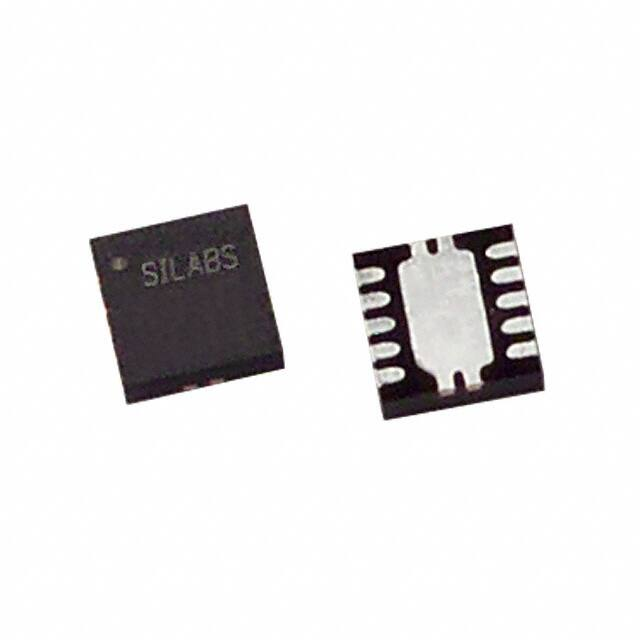


 工商网监
湘ICP备2023018690号
工商网监
湘ICP备2023018690号
