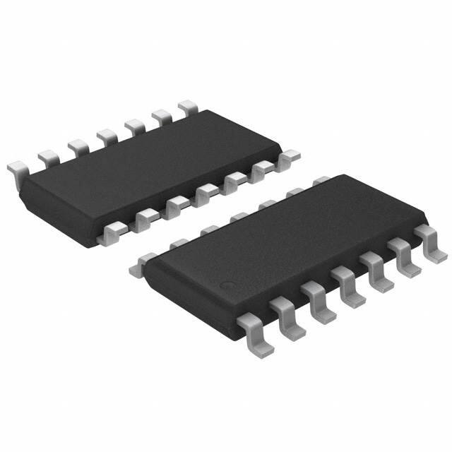
HCF40106
Hex Schmitt trigger
Datasheet - production data
Applications
Automotive
Industrial
SO-14
Computer
Consumer
Features
Description
Schmitt trigger action with no external
components
The HCF40106 is a monolithic integrated circuit
fabricated in metal oxide semiconductor
technology available in an SO-14 package.
Hysteresis voltage typically:
0.9 V at VDD = 5 V
2.3 V at VDD =10 V
3.5 V at VDD =15 V
Noise immunity greater than 50%
No limit on input rise and fall times
Low VDD to VSS current during slow input ramp
Standardized symmetrical output
characteristics
The HCF40106 consists of six Schmitt trigger
circuits. Each circuit functions as an inverter with
Schmitt trigger action on the input. The trigger
switches at different points for positive and
negative-going signals. The difference between
the positive voltage (VP) and the negative voltage
(VN) is defined as hysteresis voltage (VH).
Quiescent current specified up to 20 V
5 V, 10 V, and 15 V parametric ratings
Input leakage current II = 100 nA (max.) at
VDD = 18 V and TA = 25 C
100% tested for quiescent current
ESD performance
– HBM: 2 kV
– MM: 200 V
– CDM: 1 kV
Table 1. Device summary table
Order code
Temperature range
Package
HCF40106M013TR
-55 ° C to +125 ° C
SO-14
HCF40106YM013TR(1)
-40 ° C to +125 ° C
SO-14
(automotive grade)(1)
Packing
Marking
HCF40106
Tape & reel
HCF40106Y
1. Qualification and characterization according to AEC Q100 and Q003 or equivalent, advanced screening according to AEC
Q001 and Q002 or equivalent.
January 2014
This is information on a product in full production.
DocID002017 Rev 4
1/16
www.st.com
�Contents
HCF40106
Contents
1
Pin information . . . . . . . . . . . . . . . . . . . . . . . . . . . . . . . . . . . . . . . . . . . . . 3
2
Functional description . . . . . . . . . . . . . . . . . . . . . . . . . . . . . . . . . . . . . . . 4
3
Electrical characteristics . . . . . . . . . . . . . . . . . . . . . . . . . . . . . . . . . . . . . 6
4
Typical applications . . . . . . . . . . . . . . . . . . . . . . . . . . . . . . . . . . . . . . . . 10
5
Package information . . . . . . . . . . . . . . . . . . . . . . . . . . . . . . . . . . . . . . . . 12
6
Ordering information . . . . . . . . . . . . . . . . . . . . . . . . . . . . . . . . . . . . . . . 15
7
Revision history . . . . . . . . . . . . . . . . . . . . . . . . . . . . . . . . . . . . . . . . . . . 15
2/16
DocID002017 Rev 4
�HCF40106
1
Pin information
Pin information
Figure 1. Pin connections (top view)
$
�
��
9''
*� �$
�
��
)
%
�
��
/� �)
+� �%
�
��
(
&
�
��
.� �(
,� �&
�
�
'
966
�
�
-� �'
*$06����������&%
Table 2. Pin description
Pin no
Symbol
Name and function
1, 3, 5, 9, 11, 13
A, B, C, D, E, F
Data inputs
2, 4, 6, 8, 10, 12
G, H, I, J, K, L
Data outputs
7
VSS
Negative supply voltage
14
VDD
Positive supply voltage
DocID002017 Rev 4
3/16
16
�Functional description
2
HCF40106
Functional description
Figure 2. Logic diagram
����
*
�������������������
$
�������������������
9''
966
*$06����������&%�
1. All inputs protected by COS/MOS protection network.
Table 3. Truth table
Inputs (A to F)
Outputs (G to L)
L
H
H
L
Figure 3. Functional diagram
$
%
&
'
(
)
�
�
�
�
�
�
�
�
��
��
��
��
9''� ���
966� ��
4/16
DocID002017 Rev 4
*� �$
+� �%
,� �&
-� �'
.� �(
/� �)
*$06����������&%�
�HCF40106
Functional description
Figure 4. Input equivalent circuit
9''
,1387
966
*$06����������&%
DocID002017 Rev 4
5/16
16
�Electrical characteristics
3
HCF40106
Electrical characteristics
Absolute maximum ratings are those values beyond which damage to the device may occur.
Functional operation under these conditions is not implied. All voltage values are referred to
VSS pin voltage.
Table 4. Absolute maximum ratings (AMR)
Symbol
Parameter
Value
VDD
Supply voltage
-0.5 to +22
VI
DC input voltage
-0.5 to VDD + 0.5
II
DC input current
10
Power dissipation per package
200
Power dissipation per output transistor
100
Top
Operating temperature
-55 to +125
Tstg
Storage temperature
-65 to +150
PD
Unit
V
mA
mW
°C
Table 5. Recommended operating conditions
6/16
Symbol
Parameter
Value
VDD
Supply voltage
3 to 20
VI
Input voltage
0 to VDD
Top
Operating temperature
-55 to 125
DocID002017 Rev 4
Unit
V
°C
�HCF40106
Electrical characteristics
Table 6. DC specifications(1)
Test condition
Value
TA = 25 °C
Sym. Parameter
VI (V)
IL
VOH
VOL
VP
VN
VH
IOH
IOL
Quiescent
current
High level
output
voltage
Low level
output
voltage
VO (V)
|IO| (A) VDD(V)
Input
leakage
current
CI
Input
capacitance
Min.
Max.
0/10
10
0/15
15
0/20
20
0/5
5
4.95
4.95
4.95
10
9.95
9.95
9.95
0/15
15
14.95
14.95
14.95
5/0
5
0/10
很抱歉,暂时无法提供与“HCF40106YM013TR”相匹配的价格&库存,您可以联系我们找货
免费人工找货